2007 KIA CARNIVAL service
[x] Cancel search: servicePage 1121 of 1575
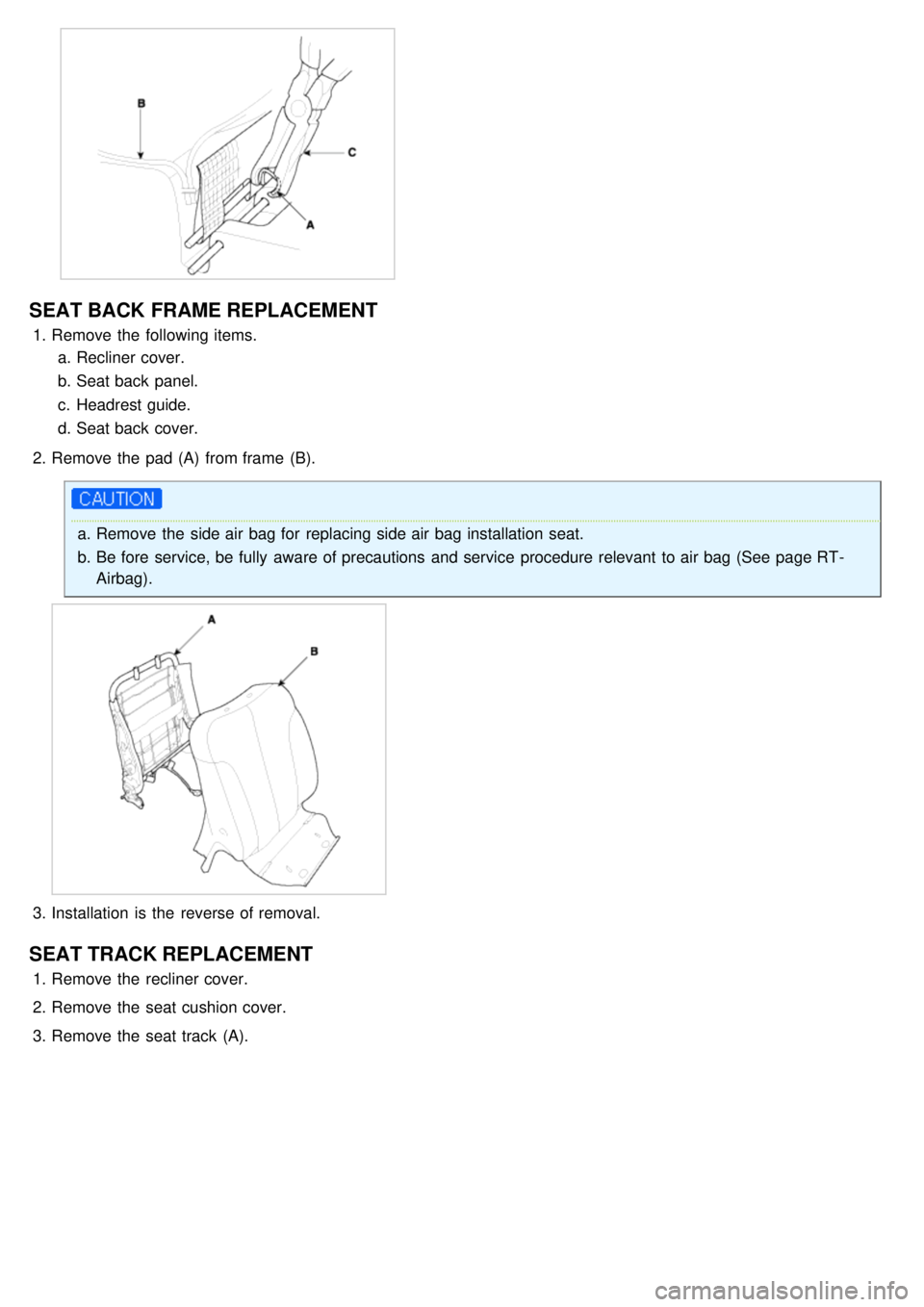
SEAT BACK FRAME REPLACEMENT
1.Remove the following items.
a. Recliner cover.
b. Seat back panel.
c. Headrest guide.
d. Seat back cover.
2. Remove the pad (A) from frame (B).
a.Remove the side air bag for replacing side air bag installation seat.
b. Be fore service, be fully aware of precautions and service procedure relevant to air bag (See page RT -
Airbag).
3.Installation is the reverse of removal.
SEAT TRACK REPLACEMENT
1.Remove the recliner cover.
2. Remove the seat cushion cover.
3. Remove the seat track (A).
Page 1331 of 1575
2007 > 2.7L V6 GASOLINE >
TROUBLESHOOTING
Check the following items prior to performing Power Sliding Door System service.
1. Manual movement
Make sure the sliding door moves manually. Place the ON/OFF switch on the overhead console in the OFF
position. Move the door manually and check for proper door fit and latch effort. Check for interference with other
body parts such as latch striker, trim, and weather seals.
2. Battery voltage
Make sure the battery is fully charged. The PSD system is an electronic device and requires a minimum battery
voltage to operate. The PSDM(Power sliding door module) monitors the battery voltage present at the PSDM input
battery input and will not permit operation if the battery voltage is out of range.
3. Fuses
Two fuses protect the battery supply to the PSDM(Power sliding door module), one for Power, and one for logic.
Check that the fuses are intact
4. Repeat Operations
Make sure the customer has not been operating the PSD repeatedly while the vehicle is turned off. The battery will
be discharged and the PSDM(Power sliding door module) will not permit operation.
5. Vehicle on Steep Grade
Make sure the customer has not been operating the PSD system when the vehicle is parked on a steep grade
(greater than 30%). The system will operate but the force of gravity and normal flex of the vehicle body may affect
proper operation.
6. Obstacle Detection
The obstacle detection force is not adjustable. Factors that may affect the force are vehicle grade, battery voltage,
or dirt in sliding door tracks.
7. Outside handle response time
When the vehicle has been parked and OFF, there may be a delay before power operation starts after the outside
handle is pulled. This is normal because the PSDM(Power sliding door module) must wake up and check for proper
conditions before starting a power open operation.
8. The sliding doors are not identical. Open and close times and obstacle detection efforts may vary when comparing
the two doors. This is normal and is caused by vehicle build conditions such as door fit and rolling resistance.
9. Scan tool Diagnostic tool
Connect Scan tool to the K- line and check status of system.
POWER SLIDING DOOR SYSTEM DIAGNOSIS
CONDITION POSSIBLE CAUSES CORRECTION
Sliding Door opens
unexpectedly Accidental activation or failure of
open/close command switch
Check for shorted or defective switch
Failure of latch assembly Check wiring connections
Check for diagnostic trouble codes
Failure of Power Sliding Door or Body
Control module Disconnect then reconnect battery or fuse to
reset module and function sliding door. If no
function exists check for loose wire
connections. See Body Diagnostic Manual for
detailed procedures
Sliding Door will not power
open or close Not in Park or false indication
Check switch status with SCAN tool
Battery voltage at PSDM is too low
<9.5V to start operation and
<8.0V to continue operation Check for proper voltage at the PSDM.
Charge battery
Blown fuse Check for blown fuse
BCM or sliding door control module
Page 1369 of 1575
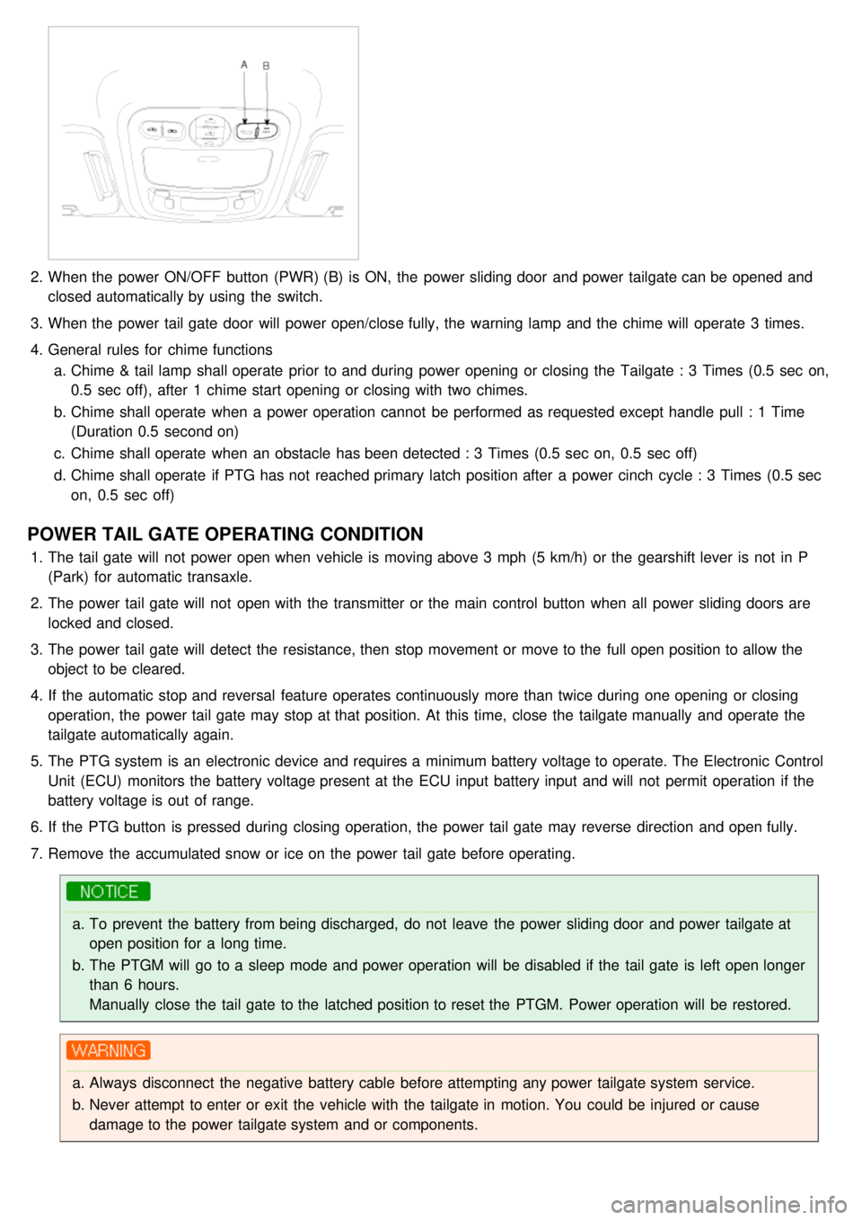
2.When the power ON/OFF button (PWR) (B) is ON, the power sliding door and power tailgate can be opened and
closed automatically by using the switch.
3. When the power tail gate door will power open/close fully, the warning lamp and the chime will operate 3 times.
4. General rules for chime functions
a. Chime & tail lamp shall operate prior to and during power opening or closing the Tailgate : 3 Times (0.5 sec on,
0.5 sec off), after 1 chime start opening or closing with two chimes.
b. Chime shall operate when a power operation cannot be performed as requested except handle pull : 1 Time
(Duration 0.5 second on)
c. Chime shall operate when an obstacle has been detected : 3 Times (0.5 sec on, 0.5 sec off)
d. Chime shall operate if PTG has not reached primary latch position after a power cinch cycle : 3 Times (0.5 sec
on, 0.5 sec off)
POWER TAIL GATE OPERATING CONDITION
1.The tail gate will not power open when vehicle is moving above 3 mph (5 km/h) or the gearshift lever is not in P
(Park) for automatic transaxle.
2. The power tail gate will not open with the transmitter or the main control button when all power sliding doors are
locked and closed.
3. The power tail gate will detect the resistance, then stop movement or move to the full open position to allow the
object to be cleared.
4. If the automatic stop and reversal feature operates continuously more than twice during one opening or closing
operation, the power tail gate may stop at that position. At this time, close the tailgate manually and operate the
tailgate automatically again.
5. The PTG system is an electronic device and requires a minimum battery voltage to operate. The Electronic Control
Unit (ECU) monitors the battery voltage present at the ECU input battery input and will not permit operation if the
battery voltage is out of range.
6. If the PTG button is pressed during closing operation, the power tail gate may reverse direction and open fully.
7. Remove the accumulated snow or ice on the power tail gate before operating.
a.To prevent the battery from being discharged, do not leave the power sliding door and power tailgate at
open position for a long time.
b. The PTGM will go to a sleep mode and power operation will be disabled if the tail gate is left open longer
than 6 hours.
Manually close the tail gate to the latched position to reset the PTGM. Power operation will be restored.
a.Always disconnect the negative battery cable before attempting any power tailgate system service.
b. Never attempt to enter or exit the vehicle with the tailgate in motion. You could be injured or cause
damage to the power tailgate system and or components.
Page 1503 of 1575
2007 > 2.7L V6 GASOLINE >
DESCRIPTION
The immobilizer system will disable the vehicle unless the proper ignition key is used, in addition to the currently
available anti- theft systems such as car alarms, the immobilizer system aims to drastically reduce the rate of auto
theft.
1. SMARTRA type immobilizer
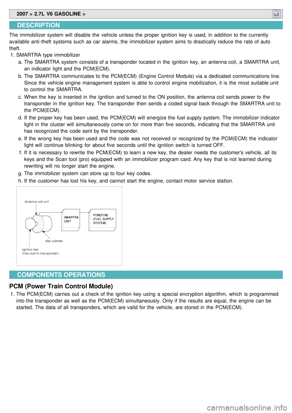
a. The SMARTRA system consists of a transponder located in the ignition key, an antenna coil, a SMARTRA unit,
an indicator light and the PCM(ECM).
b. The SMARTRA communicates to the PCM(ECM) (Engine Control Module) via a dedicated communications line.
Since the vehicle engine management system is able to control engine mobilization, it is the most suitable unit
to control the SMARTRA.
c. When the key is inserted in the ignition and turned to the ON position, the antenna coil sends power to the
transponder in the ignition key. The transponder then sends a coded signal back through the SMARTRA unit to
the PCM(ECM).
d. If the proper key has been used, the PCM(ECM) will energize the fuel supply system. The immobilizer indicator
light in the cluster will simultaneously come on for more than five seconds, indicating that the SMARTRA unit
has recognized the code sent by the transponder.
e. If the wrong key has been used and the code was not received or recognized by the PCM(ECM) the indicator
light will continue blinking for about five seconds until the ignition switch is turned OFF.
f. If it is necessary to rewrite the PCM(ECM) to learn a new key, the dealer needs the customer's vehicle, all its
keys and the Scan tool (pro) equipped with an immobilizer program card. Any key that is not learned during
rewriting will no longer start the engine.
g. The immobilizer system can store up to four key codes.
h. If the customer has lost his key, and cannot start the engine, contact motor service station.
COMPONENTS OPERATIONS
PCM (Power Train Control Module)
1. The PCM(ECM) carries out a check of the ignition key using a special encryption algorithm, which is programmed
into the transponder as well as the PCM(ECM) simultaneously. Only if the results are equal, the engine can be
started. The data of all transponders, which are valid for the vehicle, are stored in the PCM(ECM).
Page 1508 of 1575
2007 > 2.7L V6 GASOLINE >
TEACHING PROCEDURES
1.Key Teaching Procedure
Key teaching must be done after replacing an inoperative PCM(ECM) or when providing additional keys to the
vehicle owner.
The procedure starts with an PCM(ECM) request for vehicle specific data (PIN code: 6digits) from the tester. The
"virgin" PCM(ECM) stores the vehicle specific data and the key teaching can be started. The "learnt" PCM(ECM)
compares the vehicle specific data from the tester with the stored data. If the data are correct, the teaching can
proceed.
If incorrect vehicle specific data have been sent to the PCM(ECM) three times, the PCM(ECM) will reject the
request of key teaching for one hour. This time cannot be reduced by disconnecting the battery or any other
manipulation. After reconnecting the battery, the timer starts again for one hour.
The key teaching is done by ignition on with the key and additional tester commands. The PCM(ECM) stores the
relevant data in the EEPROM and in the transponder. Then the PCM(ECM) runs the authentication required for
confirmation of the teaching process. The successful programming is then confirmed by a message to the tester.
If the key is already known to the PCM(ECM) from a previous teaching, the authentication will be accepted and the
EEPROM data are updated. There is no changed transponder content (this is impossible for a learnt transponder).
The attempt to repeatedly teach a key, which has been taught already during the same teaching cycle, is
recognized by the PCM(ECM). This rejects the key and a message is sent to the tester.
The PCM(ECM) rejects invalid keys, which are presented for teaching. A message is sent to the tester. The key
can be invalid due to faults in the transponder or other reasons, which result from unsuccessful programming of
data. If the PCM(ECM) detects different authenticators of a transponder and an PCM(ECM), the key is considered
to be invalid.
The maximum number of taught keys is 4
If an error occurs during the Immobilizer Service Menu, the PCM(ECM) status remains unchanged and a specific
fault code is stored.
If the PCM(ECM) status and the key status do not match for teaching of keys, the tester procedure will be stopped
and a specific fault code will be stored at PCM(ECM).
Page 1512 of 1575
2.User Password Teaching Procedure
The user password for limp home is taught at the service station. The owner of the vehicle can select a number
with four digits.
User password teaching is only accepted by a "learnt" PCM(ECM). Before first teaching of user password to an
PCM(ECM), the status of the password is "virgin" No limp home function is possible.
The teaching is started by ignition on, with a valid key and sending the user password by tester. After successful
teaching, the status of the user password changes from "virgin" to "learnt"
The learnt user password can also be changed. This can be done if the user password status is "learnt" and the
tester sends authorization of access, either the old user password or the vehicle specific data. After correct
authorization, the PCM(ECM) requests the new user password. The status remains "learnt" and the new user
password will be valid for the next limp home mode.
If incorrect user passwords or wrong vehicle specific data have been sent to the PCM(ECM) three times, the
PCM(ECM) will reject the request to change the password for one hour. This time cannot be reduced by
disconnecting the battery or any other actions. After reconnecting the battery, the timer starts again for one hour.
(1) User password teaching
Page 1515 of 1575
LIMP HOME FUNCTION
1.LIMP HOME BY TESTER
If the PCM(ECM) detects the fault of the SMARTRA or transponder, the PCM(ECM) will allow limp home function of
the immobilizer. Limp home is only possible if the user password (4 digits) has been given to the PCM(ECM)
before. This password can be selected by the vehicle owner and is programmed at the service station.
The user password can be sent to the PCM(ECM) via the special tester menu.
Only if the PCM(ECM) is in status "learnt" and the user password status is "learnt" and the user password is
correct, the PCM(ECM) will be unlocked for a period of time (30 sec.). The engine can only be started during this
time. After the time has elapsed, engine start is not possible.
If the wrong user password is sent, the PCM(ECM) will reject the request of limp home for one hour. Disconnecting
the battery or any other action cannot reduce this time. After connecting the battery to the PCM(ECM), the timer
starts again for one hour.