2007 KIA CARNIVAL ECO mode
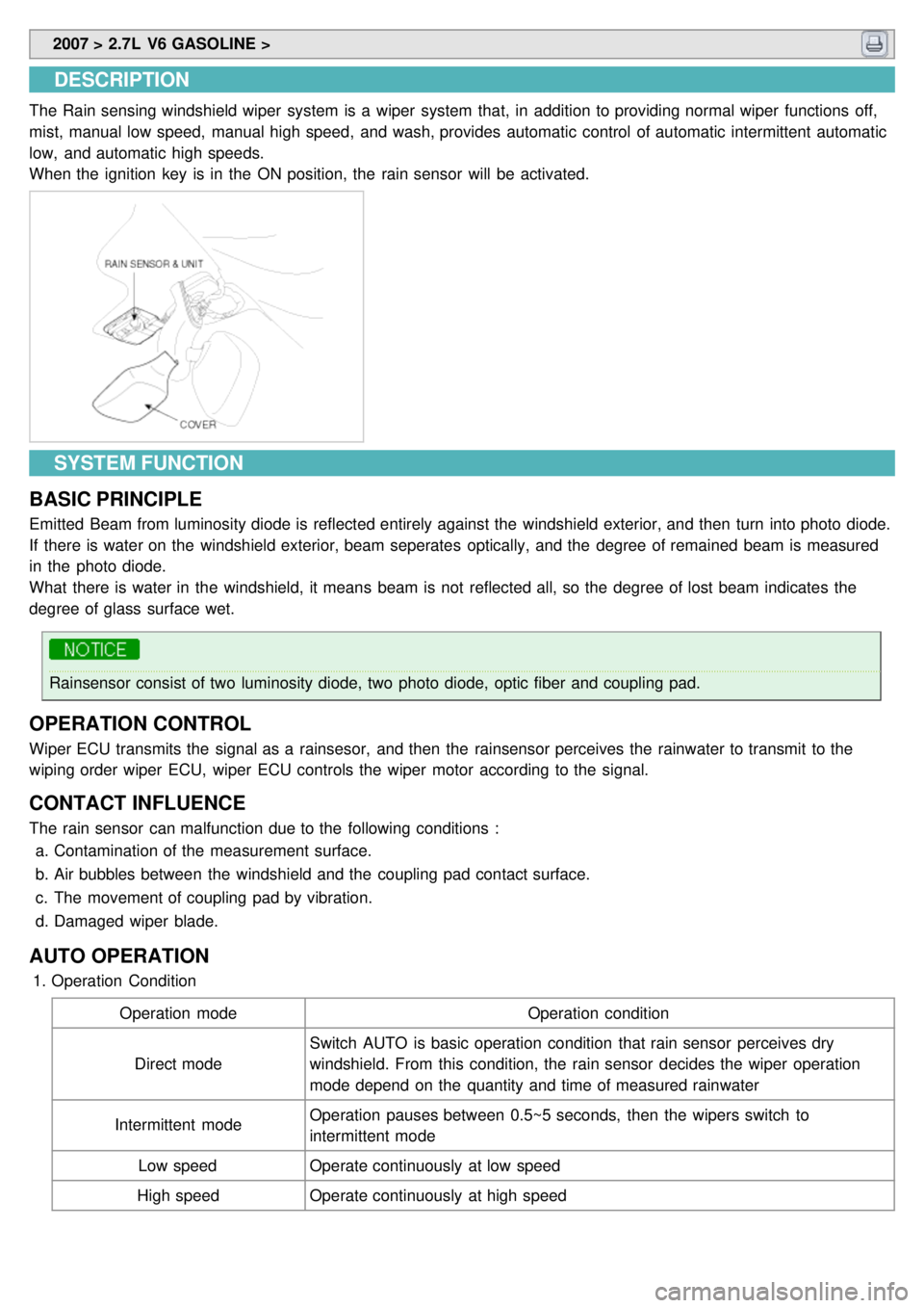
[x] Cancel search: ECO modePage 1234 of 1575
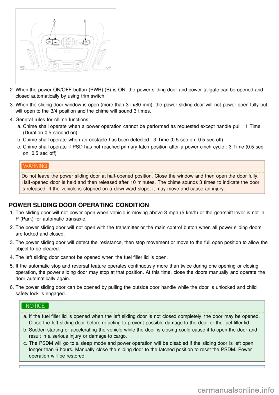
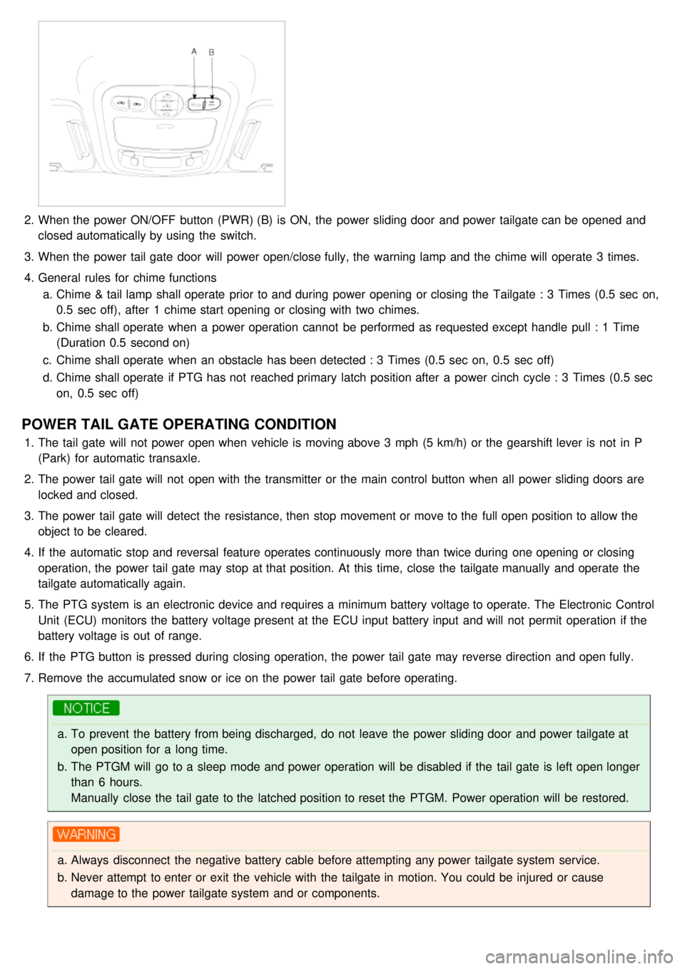
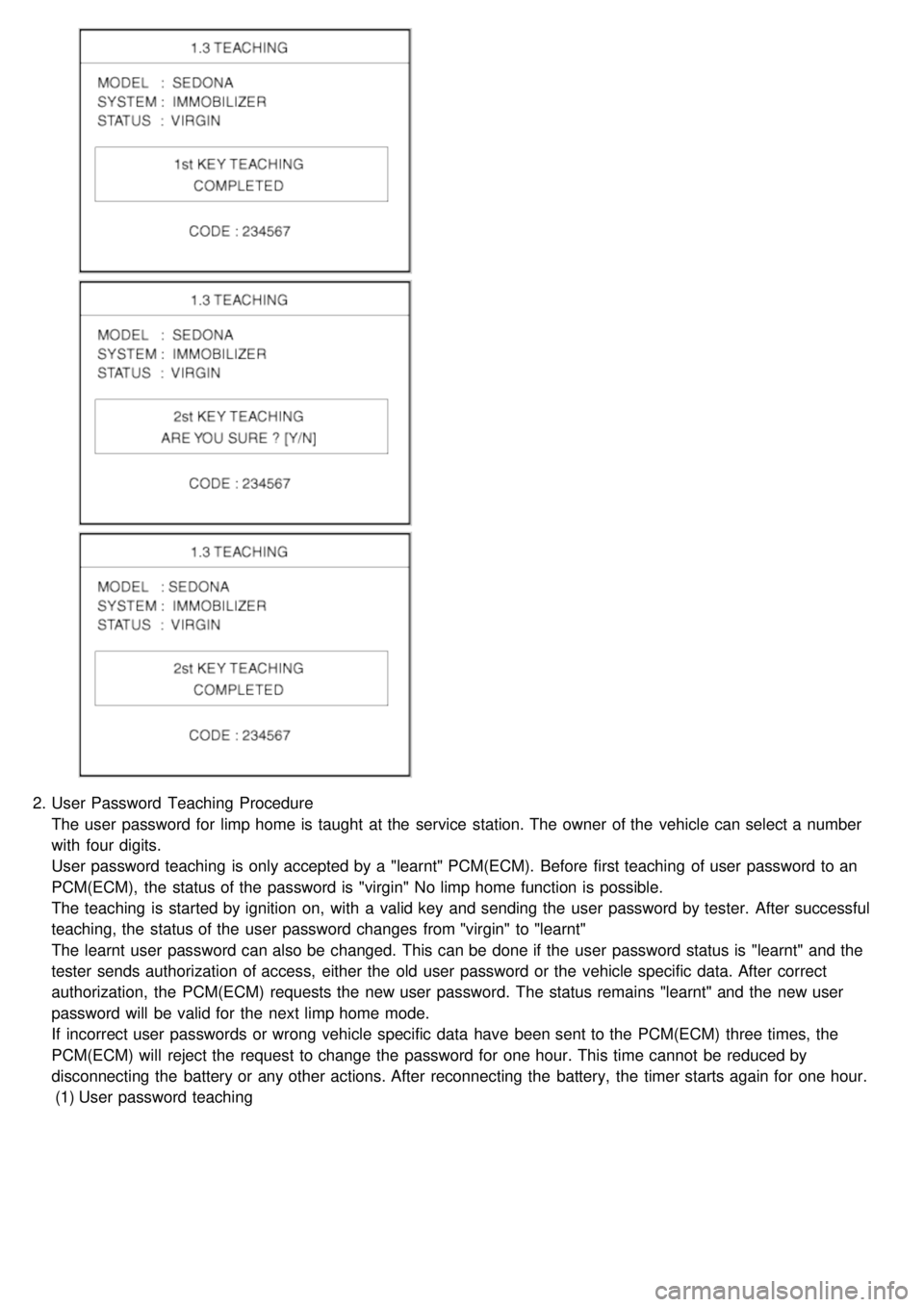
CLOSE signal.
b. RAM will pass this signal to LH PSD and RH PSD then the burglar alarm state is decided depending on the
vehicle condition.
f. PTG open/close
a. Only with the information received by RKE, the burglar alarm system cannot distinguish the OPEN signal from
CLOSE signal.
b. RAM will pass this signal to PTG module then the burglar alarm state is decided depending on the vehicle
condition.
g. Panic by key fob
a. Whenever this signal is received, the PANIC function is activated (unless the system is already in an ALARM
state).
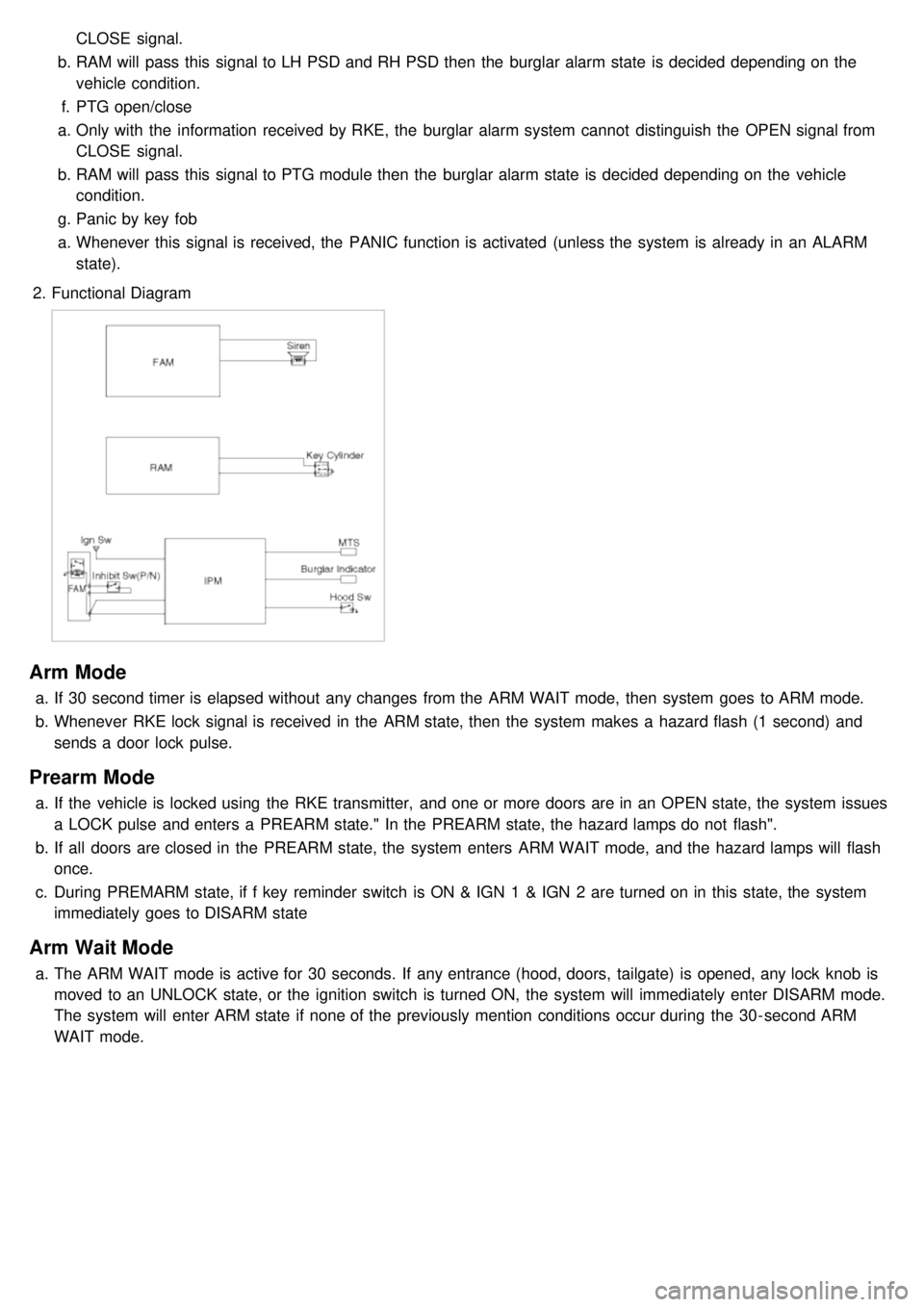
2. Functional Diagram
Arm Mode
a.If 30 second timer is elapsed without any changes from the ARM WAIT mode, then system goes to ARM mode.
b. Whenever RKE lock signal is received in the ARM state, then the system makes a hazard flash (1 second) and
sends a door lock pulse.
Prearm Mode
a.If the vehicle is locked using the RKE transmitter, and one or more doors are in an OPEN state, the system issues
a LOCK pulse and enters a PREARM state." In the PREARM state, the hazard lamps do not flash".
b. If all doors are closed in the PREARM state, the system enters ARM WAIT mode, and the hazard lamps will flash
once.
c. During PREMARM state, if f key reminder switch is ON & IGN 1 & IGN 2 are turned on in this state, the system
immediately goes to DISARM state
Arm Wait Mode
a.The ARM WAIT mode is active for 30 seconds. If any entrance (hood, doors, tailgate) is opened, any lock knob is
moved to an UNLOCK state, or the ignition switch is turned ON, the system will immediately enter DISARM mode.
The system will enter ARM state if none of the previously mention conditions occur during the 30- second ARM
WAIT mode.
Page 1235 of 1575
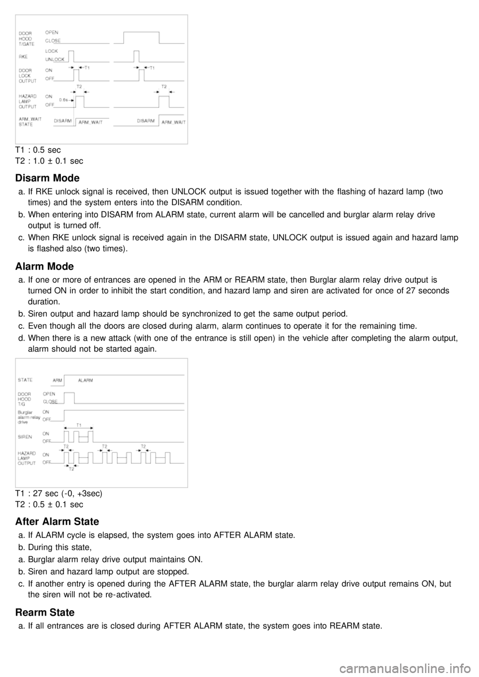
T1 : 0.5 sec
T2 : 1.0 ± 0.1 sec
Disarm Mode
a.If RKE unlock signal is received, then UNLOCK output is issued together with the flashing of hazard lamp (two
times) and the system enters into the DISARM condition.
b. When entering into DISARM from ALARM state, current alarm will be cancelled and burglar alarm relay drive
output is turned off.
c. When RKE unlock signal is received again in the DISARM state, UNLOCK output is issued again and hazard lamp
is flashed also (two times).
Alarm Mode
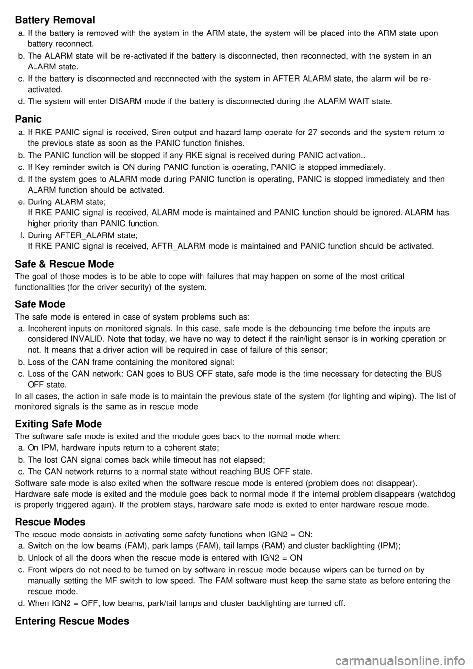
a.If one or more of entrances are opened in the ARM or REARM state, then Burglar alarm relay drive output is
turned ON in order to inhibit the start condition, and hazard lamp and siren are activated for once of 27 seconds
duration.
b. Siren output and hazard lamp should be synchronized to get the same output period.
c. Even though all the doors are closed during alarm, alarm continues to operate it for the remaining time.
d. When there is a new attack (with one of the entrance is still open) in the vehicle after completing the alarm output,
alarm should not be started again.
T1 : 27 sec ( - 0, +3sec)
T2 : 0.5 ± 0.1 sec
After Alarm State
a.If ALARM cycle is elapsed, the system goes into AFTER ALARM state.
b. During this state,
a. Burglar alarm relay drive output maintains ON.
b. Siren and hazard lamp output are stopped.
c. If another entry is opened during the AFTER ALARM state, the burglar alarm relay drive output remains ON, but
the siren will not be re- activated.
Rearm State
a.If all entrances are is closed during AFTER ALARM state, the system goes into REARM state.
Page 1236 of 1575
Battery Removal
a.If the battery is removed with the system in the ARM state, the system will be placed into the ARM state upon
battery reconnect.
b. The ALARM state will be re- activated if the battery is disconnected, then reconnected, with the system in an
ALARM state.
c. If the battery is disconnected and reconnected with the system in AFTER ALARM state, the alarm will be re-
activated.
d. The system will enter DISARM mode if the battery is disconnected during the ALARM WAIT state.
Panic
a.If RKE PANIC signal is received, Siren output and hazard lamp operate for 27 seconds and the system return to
the previous state as soon as the PANIC function finishes.
b. The PANIC function will be stopped if any RKE signal is received during PANIC activation..
c. If Key reminder switch is ON during PANIC function is operating, PANIC is stopped immediately.
d. If the system goes to ALARM mode during PANIC function is operating, PANIC is stopped immediately and then
ALARM function should be activated.
e. During ALARM state;
If RKE PANIC signal is received, ALARM mode is maintained and PANIC function should be ignored. ALARM has
higher priority than PANIC function.
f. During AFTER_ALARM state;
If RKE PANIC signal is received, AFTR_ALARM mode is maintained and PANIC function should be activated.
Safe & Rescue Mode
The goal of those modes is to be able to cope with failures that may happen on some of the most critical
functionalities (for the driver security) of the system.
Safe Mode
The safe mode is entered in case of system problems such as:
a. Incoherent inputs on monitored signals. In this case, safe mode is the debouncing time before the inputs are
considered INVALID. Note that today, we have no way to detect if the rain/light sensor is in working operation or
not. It means that a driver action will be required in case of failure of this sensor;
b. Loss of the CAN frame containing the monitored signal:
c. Loss of the CAN network: CAN goes to BUS OFF state, safe mode is the time necessary for detecting the BUS
OFF state.
In all cases, the action in safe mode is to maintain the previous state of the system (for lighting and wiping). The list of
monitored signals is the same as in rescue mode
Exiting Safe Mode
The software safe mode is exited and the module goes back to the normal mode when: a. On IPM, hardware inputs return to a coherent state;
b. The lost CAN signal comes back while timeout has not elapsed;
c. The CAN network returns to a normal state without reaching BUS OFF state.
Software safe mode is also exited when the software rescue mode is entered (problem does not disappear).
Hardware safe mode is exited and the module goes back to normal mode if the internal problem disappears (watchdog
is properly triggered again). If the problem stays, hardware safe mode is exited to enter hardware rescue mode.
Rescue Modes
The rescue mode consists in activating some safety functions when IGN2 = ON: a. Switch on the low beams (FAM), park lamps (FAM), tail lamps (RAM) and cluster backlighting (IPM);
b. Unlock of all the doors when the rescue mode is entered with IGN2 = ON
c. Front wipers do not need to be turned on by software in rescue mode because wipers can be turned on by
manually setting the MF switch to low speed. The FAM software must keep the same state as before entering the
rescue mode.
d. When IGN2 = OFF, low beams, park/tail lamps and cluster backlighting are turned off.
Entering Rescue Modes
Page 1259 of 1575
2007 > 2.7L V6 GASOLINE >
DESCRIPTION
An optimal seat position set by a driver can be memorized in P/seat unit by memory SW and position SW, which
enables restoration of seat position set by the driver despite seat adjustments.
Furthermore, data is transmitted between P/seat and IPM, DDM, ADM, RAM, FAM, CLUSTER through CAN BUS.
Seat position presets cannot be recalled while driving. An emergency stop function is provided; additional functions are
described below.
1. It conducts manual operation of seat by CAN BUS data transmitted by DDM as well as that of adjustable pedal by
CAN BUS data transmitted by IPM received when operating SW manually.
2. Manual SW behavior when communication stops (back- up behavior)
a. Slide front/rear
b. Recline front/rear
c. Position control of slide motor is possible by manual SW even in case of congestion in CPU or removal of a
fuse for P/seat unit B.
3. 2 memory locations are provided for storing seat, outside mirror, and adjustable pedal presets.
4. The driver seat can be set to slide rearward when the ignition key is removed, and forward when the key is
inserted.
5. 2 additional presets for seat, mirror, and adjustable pedal position can be stored with the RKE transmitter.
OPERATION
MANUAL OPERATION
Manual operation of the driver seat and adjustable pedals is possible provided the transaxle is in 'P' range and the
vehicle speed is 0 MPH. Operation of the manual controls overrides any automatic operation commanded via CAN.
MEMORY OPERATION
1. Pressing the 'M' button on the control panel will place the system into memory storage mode and will result in a
single pulse from the output buzzer.
2. If one of the memory location buttons is pressed and held within 5 seconds of pressing the 'M' button, the output
buzzer will pulse twice to indicate successful storage of seat, mirror, and adjustable pedal positions.
3. The ignition switch must be in the RUN or START position, the vehicle speed must be 0 MPH, and the transaxle
must be in 'P' range to store memory presets.
4. Pressing the 'M' button while recalling a stored preset will halt the preset recall operation.
5. Memory will be cleared if battery is removed.
MEMORY REPLAY OPERATION
1.Pressing one of the memory location buttons will result in the driver seat, outside mirrors, and adjustable pedals
being positioned based on the stored preset data.
2. The ignition switch must be in the RUN position, the transaxle must be in 'P' range, the vehicle speed must be 0
MPH, and the manual functions must not be in operation to recall stored presets.
3. Others
a. Play operation not recorded in the position switch will not be conducted and there will be no buzzer output.
b. If other data is received during preset recall operation, the most recent preset recall signal will take
precedence.
c. If engine is started during preset recall operation, halt preset recall operation, and resume it toward target
position 100ms after Ignition switch is returned to "RUN". However, if the START state lasts over 5 sec., it will
not resume even after returning to RUN.
d. If preset recall order is received during engine start, preset recall operation is inhibited.
e. If input from manual switch for seat and adjust pedal occurs during preset recall operation of seat and adjust
pedal, halt all their preset recall operations.
f. If an error occurs during manual operation of seat and adjust pedal, delete Memory.
Page 1326 of 1575
2.When the power ON/OFF button (PWR) (B) is ON, the power sliding door and power tailgate can be opened and
closed automatically by using trim switch.
3. When the sliding door window is open (more than 3 in/80 mm), the power sliding door will not power open fully but
will open to the 3/4 position and the chime will sound 3 times.
4. General rules for chime functions
a. Chime shall operate when a power operation cannot be performed as requested except handle pull : 1 Time
(Duration 0.5 second on)
b. Chime shall operate when an obstacle has been detected : 3 Time (0.5 sec on, 0.5 sec off)
c. Chime shall operate if PSD has not reached primary latch position after a power cinch cycle : 3 Time (0.5 sec
on, 0.5 sec off)
Do not leave the power sliding door at half- opened position. Close the window and then open the door fully.
Half - opened door is held and then released after 10 minutes. The chime sounds 3 times to indicate the door
is released. If the vehicle is stopped on a downward slope, it may move and cause an injury.
POWER SLIDING DOOR OPERATING CONDITION
1.The sliding door will not power open when vehicle is moving above 3 mph (5 km/h) or the gearshift lever is not in
P (Park) for automatic transaxle.
2. The power sliding door will not open with the transmitter or the main control button when all power sliding doors
are locked and closed.
3. The power sliding door will detect the resistance, then stop movement or move to the full open position to allow the
object to be cleared.
4. The left sliding door cannot be opened when the fuel filler lid is open.
5. If the automatic stop and reversal feature operates continuously more than twice during one opening or closing
operation, the power sliding door may stop at that position. At this time, close the doors manually and operate the
door automatically again.
6. The power sliding door can be opened by pulling the outside door handle while the door is unlocked and child
safety lock is engaged.
a.If the fuel filler lid is opened when the left sliding door is not closed completely, the door may be opened.
Close the left sliding door before refueling to prevent possible damage to the door or the fuel filler lid.
b. Sudden starting or accelerating the vehicle while the door is closing could cause it to open the door and
result in a serious injury or damage to cargo.
c. The PSDM will go to a sleep mode and power operation will be disabled if the sliding door is left open
longer than 6 hours. Manually close the sliding door to the latched position to reset the PSDM. Power
operation will be restored.
Page 1369 of 1575
2.When the power ON/OFF button (PWR) (B) is ON, the power sliding door and power tailgate can be opened and
closed automatically by using the switch.
3. When the power tail gate door will power open/close fully, the warning lamp and the chime will operate 3 times.
4. General rules for chime functions
a. Chime & tail lamp shall operate prior to and during power opening or closing the Tailgate : 3 Times (0.5 sec on,
0.5 sec off), after 1 chime start opening or closing with two chimes.
b. Chime shall operate when a power operation cannot be performed as requested except handle pull : 1 Time
(Duration 0.5 second on)
c. Chime shall operate when an obstacle has been detected : 3 Times (0.5 sec on, 0.5 sec off)
d. Chime shall operate if PTG has not reached primary latch position after a power cinch cycle : 3 Times (0.5 sec
on, 0.5 sec off)
POWER TAIL GATE OPERATING CONDITION
1.The tail gate will not power open when vehicle is moving above 3 mph (5 km/h) or the gearshift lever is not in P
(Park) for automatic transaxle.
2. The power tail gate will not open with the transmitter or the main control button when all power sliding doors are
locked and closed.
3. The power tail gate will detect the resistance, then stop movement or move to the full open position to allow the
object to be cleared.
4. If the automatic stop and reversal feature operates continuously more than twice during one opening or closing
operation, the power tail gate may stop at that position. At this time, close the tailgate manually and operate the
tailgate automatically again.
5. The PTG system is an electronic device and requires a minimum battery voltage to operate. The Electronic Control
Unit (ECU) monitors the battery voltage present at the ECU input battery input and will not permit operation if the
battery voltage is out of range.
6. If the PTG button is pressed during closing operation, the power tail gate may reverse direction and open fully.
7. Remove the accumulated snow or ice on the power tail gate before operating.
a.To prevent the battery from being discharged, do not leave the power sliding door and power tailgate at
open position for a long time.
b. The PTGM will go to a sleep mode and power operation will be disabled if the tail gate is left open longer
than 6 hours.
Manually close the tail gate to the latched position to reset the PTGM. Power operation will be restored.
a.Always disconnect the negative battery cable before attempting any power tailgate system service.
b. Never attempt to enter or exit the vehicle with the tailgate in motion. You could be injured or cause
damage to the power tailgate system and or components.
Page 1434 of 1575
2007 > 2.7L V6 GASOLINE >
DESCRIPTION
The Rain sensing windshield wiper system is a wiper system that, in addition to providing normal wiper functions off,
mist, manual low speed, manual high speed, and wash, provides automatic control of automatic intermittent automatic
low, and automatic high speeds.
When the ignition key is in the ON position, the rain sensor will be activated.
SYSTEM FUNCTION
BASIC PRINCIPLE
Emitted Beam from luminosity diode is reflected entirely against the windshield exterior, and then turn into photo diode.
If there is water on the windshield exterior, beam seperates optically, and the degree of remained beam is measured
in the photo diode.
What there is water in the windshield, it means beam is not reflected all, so the degree of lost beam indicates the
degree of glass surface wet.
Rainsensor consist of two luminosity diode, two photo diode, optic fiber and coupling pad.
OPERATION CONTROL
Wiper ECU transmits the signal as a rainsesor, and then the rainsensor perceives the rainwater to transmit to the
wiping order wiper ECU, wiper ECU controls the wiper motor according to the signal.
CONTACT INFLUENCE
The rain sensor can malfunction due to the following conditions : a. Contamination of the measurement surface.
b. Air bubbles between the windshield and the coupling pad contact surface.
c. The movement of coupling pad by vibration.
d. Damaged wiper blade.
AUTO OPERATION
1.Operation Condition
Operation mode Operation condition
Direct mode Switch AUTO is basic operation condition that rain sensor perceives dry
windshield. From this condition, the rain sensor decides the wiper operation
mode depend on the quantity and time of measured rainwater
Intermittent mode Operation pauses between 0.5~5 seconds, then the wipers switch to
intermittent mode
Low speed Operate continuously at low speed
High speed Operate continuously at high speed
Page 1512 of 1575
2.User Password Teaching Procedure
The user password for limp home is taught at the service station. The owner of the vehicle can select a number
with four digits.
User password teaching is only accepted by a "learnt" PCM(ECM). Before first teaching of user password to an
PCM(ECM), the status of the password is "virgin" No limp home function is possible.
The teaching is started by ignition on, with a valid key and sending the user password by tester. After successful
teaching, the status of the user password changes from "virgin" to "learnt"
The learnt user password can also be changed. This can be done if the user password status is "learnt" and the
tester sends authorization of access, either the old user password or the vehicle specific data. After correct
authorization, the PCM(ECM) requests the new user password. The status remains "learnt" and the new user
password will be valid for the next limp home mode.
If incorrect user passwords or wrong vehicle specific data have been sent to the PCM(ECM) three times, the
PCM(ECM) will reject the request to change the password for one hour. This time cannot be reduced by
disconnecting the battery or any other actions. After reconnecting the battery, the timer starts again for one hour.
(1) User password teaching