2007 KIA CARNIVAL warning light
[x] Cancel search: warning lightPage 961 of 1575

2007 > 2.7L V6 GASOLINE >
DESCRIPTION
The EBD system (Electronic Brake force Distribution) as a sub- system of the ABS system is to control the effective
adhesion utilization by the rear wheels.
It further utilizes the efficiency of highly developed ABS equipment by controlling the slip of the rear wheels in the
partial braking range.
The brake force is moved even closer to the optimum and controlled electronically, thus dispensing with the need for
the proportioning valve.
The proportioning valve, because of a mechanical device, has limitations to achieve an ideal brake force distribution
tothe rear wheels as well as to carry out the flexible brake force distribution proportioning to the vehicle load or weight
increasing. And in the event of malfunctioning, driver cannot notice whether it fails or not.
EBD controlled by the ABS Control Module, calculates the slip ratio of each wheel at all times and controls the brake
pressure of the rear wheels not to exceed that of the front wheels.
If the EBD fails, the EBD warning lamp (Parking brake lamp) lights up.
ADVANTAGES
a.Function improvement of the base - brake system.
b. Compensation for the different friction coefficients.
c. Elimination of the proportioning valve.
d. Failure recognition by the warning lamp.
Comparison between Proportioning valve and EBD
Page 1211 of 1575

2007 > 2.7L V6 GASOLINE >
DESCRIPTION
All modules are linked a low speed CAN network.
The input information for the modules is coming from both the CAN network and the hardware components
(actuatorsand sensors).
a. FAM (Front Area Module)
a. Headlamp low/high beam control (with DRL)
b. Park lamp control
c. Front fog lamp control
d. Front turn signal lamp control
e. Windshield wiper control
f. Windshield deicer
g. Diagnostics
b. IPM (In - Panel Module)
a. RKE (Remote Keyless Control)
b. VAS (Voice Alarm System)
c. Ignition key hole illumination
d. Switch indicators control
e. Panel light control
f. Seat belt warning
g. Auto light/DRL control (Logic)
h. Windshield/Rear wiper control (Logic)
i. Turn and Hazard lamp control (Logic)
j. Central door lock (Logic)
k. Windshield deicer timer
l. Rear glass defog timer
m. Gateway for ISO- 9141 (K- Line)
c. RAM (Rear Area Module)
a. Tail lamp control
b. Turn and Hazard lamp control
c. Back up lamp control
d. Rea fog lamp control
e. Stop lamp outage detection
f. Sliding door power window/Quarter glass control
g. Room lamp control
h. Rear wiper control
i. Rear glass defog
j. Fuel filler door open solenoid control
d. ADM (Assist Drive Module)
e. DDM (Driver Drive Module)
MODULE INTRODUCTION
FAM/IPM/RAM consists of a power board and an electronic board. The power board contains circuit protection devices
and switching devices. The electronic board uses Intelligent Power Switching (IPS) for HS/LS load control, logic
functions and CAN/K- Line communication. The power board and electronic board are connected with pin blocks for
the Front Area Module (FAM) and VCD (Variable Connection Displacement) for the In- Panel Module (IPM) and the
Rear Area Module (RAM).
Page 1229 of 1575

switch, the status of the ABS EBD warning, the status of the brake fluid sensor and the speed of the vehicle.
The IPM sends the park brake indicator control on the CAN network.
The indicator is lighted if the vacuum switch or ABS EBD warning are on or brake fluid sensor is low or park brake
switch is on.
If the speed of the vehicle is over 10 km/h and ignition switch is on the status RUN the park brake indicator control is
blinking at 50% duty in 0.6 second if Parking Brake switch Input is active. In this case Vacuum switch, ABS EBD
warning and Brake Fluid sensor are ignored.
The park brake indicator is blinking on the same time that the chime is ringing. If a CAN signal among Vacuum switch,
EBD warning or Brake Fluid Sens switch is INVALID, out of range or not received this CAN signal is considered to be
OFF.
If VehicleSpeed CAN signal is INVALID or not received, it is considered to be 0 kph.
Charging Voltage Control
The IPM receives on analog input the voltage of generator and sends a warning.
When the voltage of generator L pass strictly above 10V, the state of the CAN variable.
Turn Indicators Status
The status of the turn indicators are sent on the CAN network when the CAN network is available.
High Beam Status
The status of the high beam is sent on the CAN network when the CAN network is available.
Front Fog Lamp Status
The status of the front fog lamp (lightning and state of the bulbs) is sent on the CAN network when the CAN network
is available.
Doors Open Warning
The RAM receives on digital input the status of the driver door open switch and sends it on the CAN network.
The RAM receives on digital input the status of the passenger door open switch and sends it on the CAN network.
The RAM receives on digital input the status of the left sliding door open switch and sends it on the CAN network.
The RAM receives on digital input the status of the right sliding door open switch and sends it on the CAN network.
When vehicle speed is under 10 kph, with ignition key not inserted and any door OPEN, DoorsOpenWngCtrl stays ON
for 20 min and then is turned OFF.
Tailgate Open Switch Status
When vehicle speed is under 10 kph, ignition key is inserted and Tailgate open switch is OPEN, Tailgate Open
warning stays ON forever (IPM can enter sleep mode).
When vehicle speed is under 10 kph, with ignition key not inserted and lgate open switch is OPEN, Tailgate Open
warning stays ON for 20 min and then is turned OFF.
Chime Control
1.The chime warns the driver that a problem is occurred.
These warning are:
a. Seat belt
b. Parking on
c. Over speed
d. Key reminder
e. Light Warning
f. Doors Open
g. Tailgate open warning
2. Chime sound priority:
a. 1st : Seatbelt warning
b. 2nd : Overspeed warning
c. 3rd : Door open warning
d. 4th : T/Gate open warning
e. 5th : Key operated warning
f. 6th : Parking Brake warning
Page 1230 of 1575

g.7th : Light ON warning
h. 8th : Key learning sound
3. If two different warning condition happen at the same time, chime should work only for the highest warning
condition.
4. Cluster indicators should work for two warning behavior.
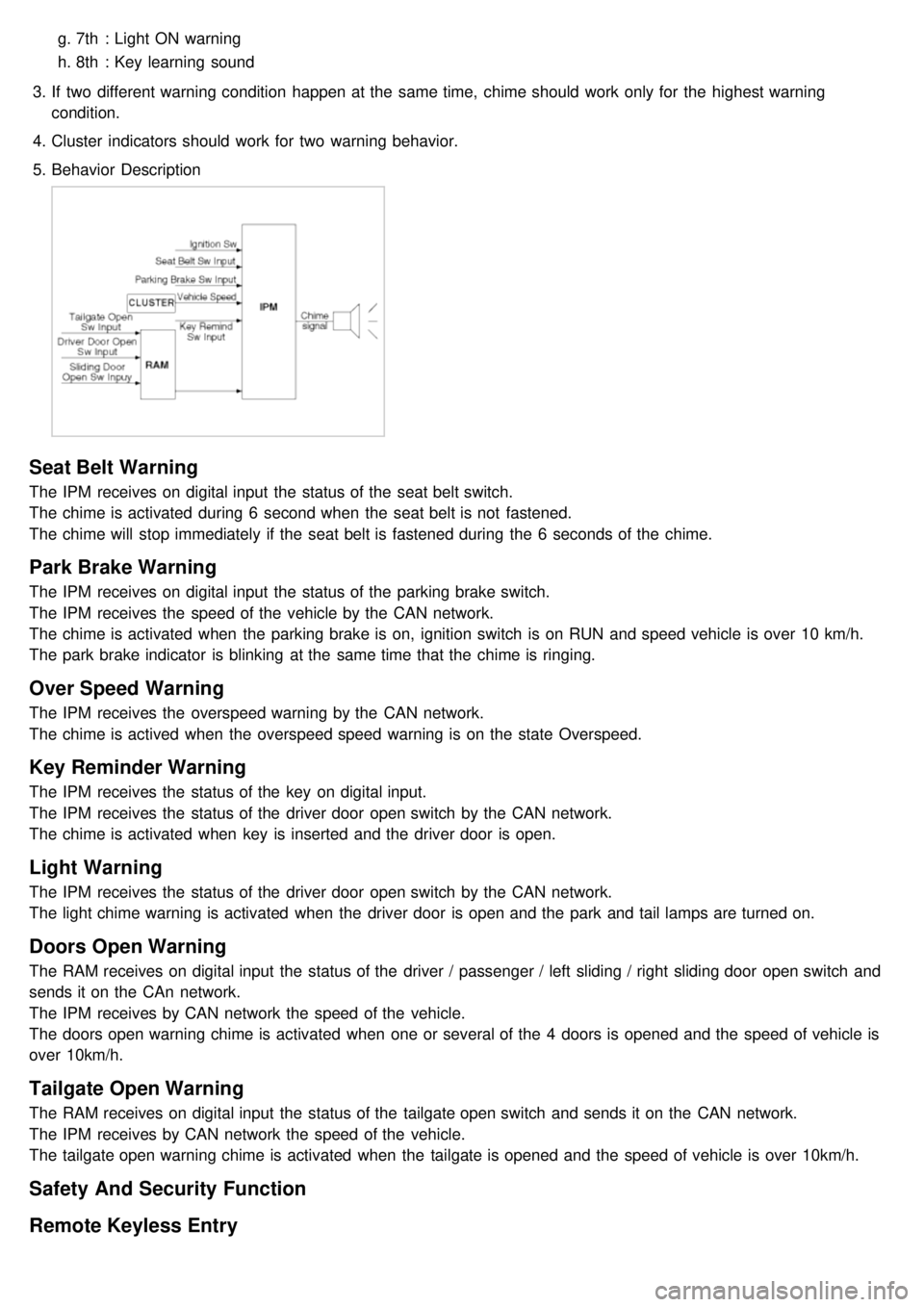
5. Behavior Description
Seat Belt Warning
The IPM receives on digital input the status of the seat belt switch.
The chime is activated during 6 second when the seat belt is not fastened.
The chime will stop immediately if the seat belt is fastened during the 6 seconds of the chime.
Park Brake Warning
The IPM receives on digital input the status of the parking brake switch.
The IPM receives the speed of the vehicle by the CAN network.
The chime is activated when the parking brake is on, ignition switch is on RUN and speed vehicle is over 10 km/h.
The park brake indicator is blinking at the same time that the chime is ringing.
Over Speed Warning
The IPM receives the overspeed warning by the CAN network.
The chime is actived when the overspeed speed warning is on the state Overspeed.
Key Reminder Warning
The IPM receives the status of the key on digital input.
The IPM receives the status of the driver door open switch by the CAN network.
The chime is activated when key is inserted and the driver door is open.
Light Warning
The IPM receives the status of the driver door open switch by the CAN network.
The light chime warning is activated when the driver door is open and the park and tail lamps are turned on.
Doors Open Warning
The RAM receives on digital input the status of the driver / passenger / left sliding / right sliding door open switch and
sends it on the CAn network.
The IPM receives by CAN network the speed of the vehicle.
The doors open warning chime is activated when one or several of the 4 doors is opened and the speed of vehicle is
over 10km/h.
Tailgate Open Warning
The RAM receives on digital input the status of the tailgate open switch and sends it on the CAN network.
The IPM receives by CAN network the speed of the vehicle.
The tailgate open warning chime is activated when the tailgate is opened and the speed of vehicle is over 10km/h.
Safety And Security Function
Remote Keyless Entry
Page 1310 of 1575

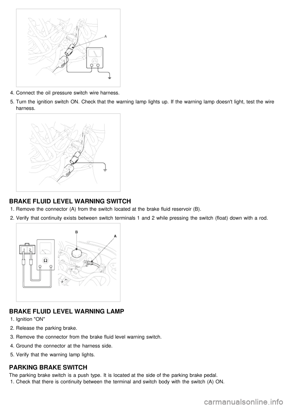
4.Connect the oil pressure switch wire harness.
5. Turn the ignition switch ON. Check that the warning lamp lights up. If the warning lamp doesn't light, test the wire
harness.
BRAKE FLUID LEVEL WARNING SWITCH
1.Remove the connector (A) from the switch located at the brake fluid reservoir (B).
2. Verify that continuity exists between switch terminals 1 and 2 while pressing the switch (float) down with a rod.
BRAKE FLUID LEVEL WARNING LAMP
1.Ignition "ON"
2. Release the parking brake.
3. Remove the connector from the brake fluid level warning switch.
4. Ground the connector at the harness side.
5. Verify that the warning lamp lights.
PARKING BRAKE SWITCH
The parking brake switch is a push type. It is located at the side of the parking brake pedal.
1. Check that there is continuity between the terminal and switch body with the switch (A) ON.