Page 1551 of 1575

2007 > 2.7L V6 GASOLINE >
DESCRIPTION
The driver door module is a part of a Controller Area Network (CAN), and performs CAN communication with the
BCM, FAM, IPM, RAM, ADM, and IMS. Driver controls driver side power window switch button located inside of the
driver side door to operate power window, mirror, door lock and unlock.
1. Two manual operations (up and down) for four p/windows. However, on the driver's seat the auto up/down
operation must be possible.
2. Opening and closing the quarter glass by the quarter glass switch.
3. Window UP/DOWN operation by RKE.
4. Manually operating the mirror position by the manual switch (Up, Down, Right, and Left)
5. Saving and replacing the mirror position by the MEMORY switch → For 2 persons
6. Saving and replacing the mirror position by RKE → For 2 persons
7. Out side mirror AUTO reverse operation
8. Out side mirror FOLD/UNFOLD power control
9. CENTRAL DOOR LOCK/UNLOCK function
10. DOOR COURTESY LAMP control
11. Out side mirror DEFOG control
12. Illumination control
CONTROL FUNCTION
POWER WINDOW CONTROL
1. This switch controls power window up/down, automatic up/down from driver & assist side.
a. Driver's power window switch sends input signal through CAN communication by the manual up/down and
automatic up/down switch input. At the same time passenger side sends manual up/down and automatic
up/down signals to the wires.
b. Each safety window ECU receives the signal and performs manual up/down and automatic up/down functions.
2. Power window lock
When the driver's power window lock switch is ON, each safety window ECU receives the power window lock
command to prohibit the operation by the passenger side doors except the driver's door.
3. Timer function
Power window switch can be controlled for 30 seconds after the ignition is turned off. This function stops
immediately even within 30 seconds if the front door is opened.
KEY REMINDER
1.If door is locked by using door lock knob after opening door while IGN KEY is inserted to KEY CYLINDER, Unlock
output will be for 1sec and there will be a series of three output signals every 0.5sec if door condition is "Lock".
2. If Key Reminder unlock message is "SHORT UNLOCK", DOOR UNLOCK lasts for 0.5sec.
3. If Key Reminder unlock message is "LONG UNLOCK", DOOR UNLOCK lasts for 1sec.
4. Remained action goes on though Key Reminder Unlock message changes to "OFF".
PRIORITY OF DOOR LOCK/UNLOCK
1.Crash Unlock > Auto Door Lock > Key Reminder > Central Door Lock
2. Higher priority signals take precedence, and will override lower priority signals.
3. If the priority is the same or low, it'll be ignored.
OUT SIDE MIRROR CONTROL BY THE SWITCH
1.If the mirror direction switch (up, down, left and right) is pressed when mirror selection switch on driver side power
window switch is in outside LH(RH) under ACC ON condition, then mirror motor moves to the corresponding
direction.
Page 1557 of 1575

2007 > 2.7L V6 GASOLINE >
DESCRIPTION
The assist door module is a part of CAN, and performs CAN communication with the BCM, FAM, IPM, RAM, DDM,
and IMS. The driver can control the power window, mirror, door(lock/unlock) by using buttons of the ADM on the door
of the driver's seat.
1. Operating the power window by buttons
2. Central Door LOCK/UNLOCK function
3. Manually operating the mirror position by the manual SW (Up, Down, Right, and Left)
4. Saving and replacing the mirror position by the memory switch → For 2 persons
5. Out side mirror AUTO reverse operation
6. Door courtesy lamp control
7. Out side mirror defog control
8. Illumination control
CONTROL FUNCTION
POWER WINDOW CONTROL
1.This switch controls power window up/down from assist side.
a. According to the input of assist Door module window, up/down switch, output window motor up/down.
b. Power window up/down control from assist side.
2. Timer function
Power window switch can be controlled for 30 seconds after the ignition is turned off. This function stops
immediately even within 30 seconds if the front door is opened.
CRASH UNLOCK
1.Under the condition "IGN ON", if Crash Sensor message from IPM is ON, Door UNLOCK is output.(5 ± 0.5sec)
AUTO DOOR LOCK
1.If the vehicle is under any of the following conditions and the condition lasts for 3sec, all doors is locked.
If message from IPM is "Door Lock Control = LOCK ALL", it will be locked for 0.5sec.
a. IGN "RUN" or "START"
b. ALT L ON (Engine is running)
c. Speed of the vehicle is 40Km/h
d. If any door is on "UNLOCK"
2. After LOCK output, if any door is not locked, there will be a series of three Lock output every 0.5sec.
3. If all doors are locked during a series of three output signals, output will be stopped.
4. If any door is not locked after a series of three output signals, output will be stopped.
KEY REMINDER
1.If door is locked by using door lock knob after opening door while IGN KEY is inserted to KEY CYLINDER, Unlock
output will be for 1sec and there will be a series of three output signals every 0.5sec if door condition is "Lock".
2. If Key Reminder unlock message is "SHORT UNLOCK", DOOR UNLOCK lasts for 0.5sec.
3. If Key Reminder unlock message is "LONG UNLOCK", DOOR UNLOCK lasts for 1sec.
4. Remained action goes on though Key Reminder Unlock message changes to "OFF".
PRIORITY OF DOOR LOCK/UNLOCK
1.Crash Unlock > Auto Door Lock > Key Reminder > Central Door Lock
2. Higher priority signals take precedence, and will override lower priority signals.
3. If the priority is the same or low, it'll be ignored.
OUT SIDE MIRROR FOLD/UNFOLD POWER CONTROL
1.Supply folding power for 30sec after ACC ON or ACC OFF.
2. FOLD/UNFOLD operation is controlled by fold switch.
Page 1562 of 1575
2007 > 2.7L V6 GASOLINE >
DESCRIPTION
SELF ADJUSTING CLUTCH(S.A.C.) COVER
a. As a clutch disc facing is worn away according to its durability, a cover weight is increasing and a clutch pedal
pressure can be more needed.
b. To make up for this defect, the self adjusting clutch system makes the requsted pedal pressure minimized so that
makes the maintenance cycle longer.
CONCENTRIC SLAVE CYLINDER-C.S.C.
It improves working efficiency and lowers the number and the weight of part by unifing clutch release control
parts(clutch release bearing ~ clutch release cylinder) in a manual transaxle.
OPERATION
CONCENTRIC SLAVE CYLINDER-C.S.C
When the clutch pedal is pressed, oil pressure is transmitted along the arrow directions shown below and that moves
the clutch slave cylinder and the diaphragm spring of the clutch cover.
Page 1567 of 1575
5.Tighten the clutch cover.
TORQUE:
24.5~35.3Nm (250~360kgf.cm, 18.1~26.0lb - ft) (6EA)
When installing the clutch cover, tighten the bolts in diagonal directions not to be bent or twisted.
* Possible problems when not following
a. When tightening the bolt completely at a time: the clutch cover can be twisted and vibration can occur.
b. On vehicles with self adjusting clutches, it is necessary to follow this caution.
c. Not following tightening torque: There can be bad torque transmission in clutch and relaxation possibility of
bolts.
INSPECTION
1.Inspect diaphragm spring wear which is in contact with a concentric slave cylinder bearing.
Page 1569 of 1575
Page 1570 of 1575
2007 > 2.7L V6 GASOLINE >
REMOVAL
Do not spill brake fluid on the vehicle; it may damage the paint if brake fluid does contact the paint, wash it off
immediately with water.
1. Remove the brake fluid fron the clutch master cylinder reservoir with a syringe.
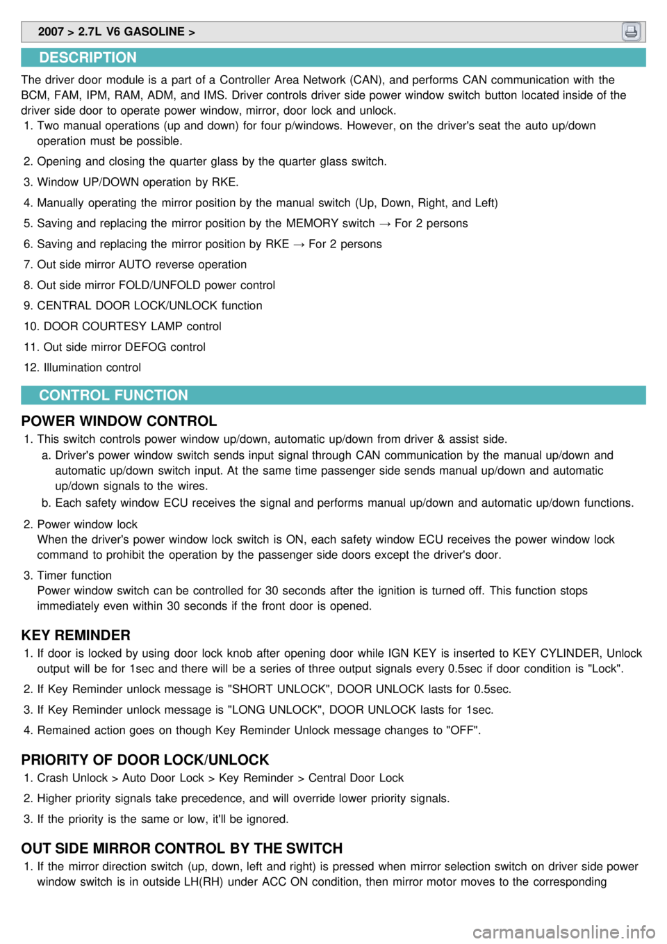
2. Clamp the clutch master cylinder hose(A). If there is no enough room for clamping, you can also clamp the hose
from the brake master cylinder side.
3.Disconnect the hose(A) from the cylinder by releasing the clutch master cylinder clamp.
4.Remove the clutch master cylinder mounting bolts(A,B).
One is the engine room, the other near the clutch pedal assembly.
Page 1571 of 1575

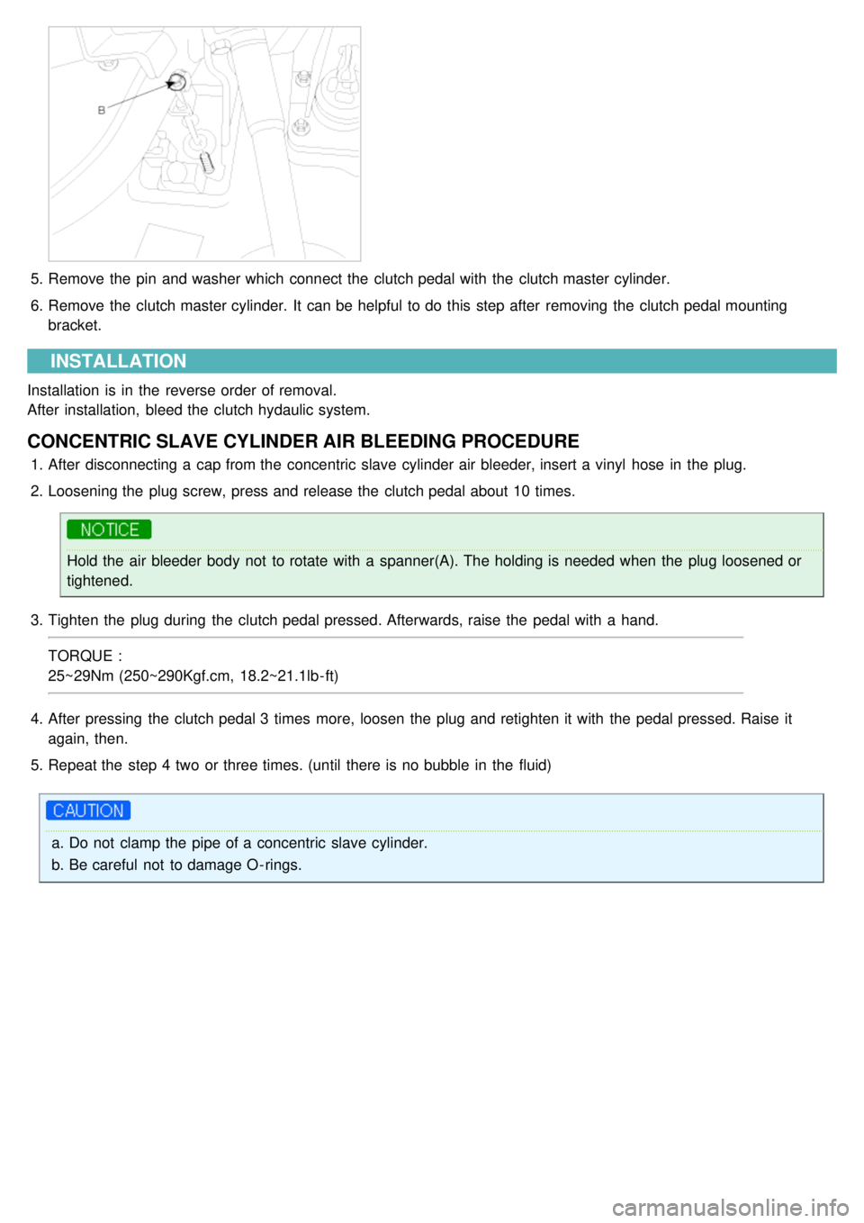
5.Remove the pin and washer which connect the clutch pedal with the clutch master cylinder.
6. Remove the clutch master cylinder. It can be helpful to do this step after removing the clutch pedal mounting
bracket.
INSTALLATION
Installation is in the reverse order of removal.
After installation, bleed the clutch hydaulic system.
CONCENTRIC SLAVE CYLINDER AIR BLEEDING PROCEDURE
1.After disconnecting a cap from the concentric slave cylinder air bleeder, insert a vinyl hose in the plug.
2. Loosening the plug screw, press and release the clutch pedal about 10 times.
Hold the air bleeder body not to rotate with a spanner(A). The holding is needed when the plug loosened or
tightened.
3. Tighten the plug during the clutch pedal pressed. Afterwards, raise the pedal with a hand.
TORQUE :
25~29Nm (250~290Kgf.cm, 18.2~21.1lb - ft)
4. After pressing the clutch pedal 3 times more, loosen the plug and retighten it with the pedal pressed. Raise it
again, then.
5. Repeat the step 4 two or three times. (until there is no bubble in the fluid)
a.Do not clamp the pipe of a concentric slave cylinder.
b. Be careful not to damage O - rings.
Page 1573 of 1575

2007 > 2.7L V6 GASOLINE >
ADJUSTMENT PROCEDURE
IGNITION LOCK SWITCH
1. Disconnect 2P- connector from a ignition lock switch.
2. Disconnect the ignition lock switch. (if you can install a tester with the switch fixed, this step can be omissible)
3. Check for continuity between terminals. (refer to the table below)
Clutch pedal position Ignition lock switch Continuity
Released ReleasedNO
Pressed PressedYES
If there is difference between what tested and the table above, replace the ignition lock switch with a new one.
If not, install the ignition lock switch and adjust the clutch pedal.
TORQUE :
8~10Nm (80~100kgf.cm, 5.8~7.2lb- ft)
Clutch pedal and Ignition lock switch
a. Inspect a ignition lock switch.
b. Remove the driver's seat mat to adjust a clutch pedal.
c. No gap between a clutch master cylinder pistion and push rod can cause clutch slip.
1. Loosen and draw out the bolt until it is off the pedal surface.
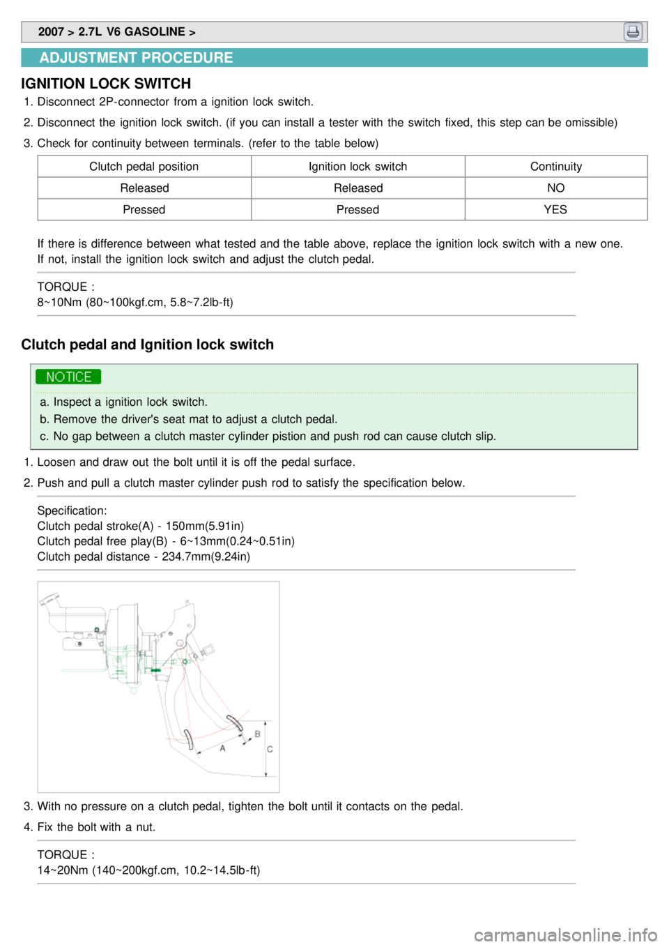
2. Push and pull a clutch master cylinder push rod to satisfy the specification below.
Specification:
Clutch pedal stroke(A) - 150mm(5.91in)
Clutch pedal free play(B) - 6~13mm(0.24~0.51in)
Clutch pedal distance - 234.7mm(9.24in)
3.With no pressure on a clutch pedal, tighten the bolt until it contacts on the pedal.
4. Fix the bolt with a nut.
TORQUE :
14~20Nm (140~200kgf.cm, 10.2~14.5lb - ft)