2007 ISUZU KB P190 water
[x] Cancel search: waterPage 20 of 6020

0B-2 MAINTENANCE AND LUBRICATION
MAINTENANCE SCHEDULE (For GENERAL EXPORT)
Items followed by an asterisk (*) require more frequent maintenance if the vehicle is driven under severe conditions.
Replace the fuel filter (**Mark) when the fuel filter indicator light is lit.
Refer to "SEVERE CONDITIONS MAINTENANCE SCHEDULE."
I : Inspect and correct or replace as necessary A : Adjust
R : Replace or change T : Tighten to specified torque L : Lubricate
SERVICE INTERVAL: × 1,000 km 5 10 15 20 25 30 35 40 45 50 55 60 65 70 75 80 85 90 95 100(Use odometer reading × 1,000 miles 3 6 9 12 15 18 21 24 27 30 33 36 39 42 45 48 51 54 57 60or months whichever
comes first)
or months 6 12 18 24 30 36 42 48 54 60 66 72 78 84 90 96 102 108 114 120
ENGINE
Idling speed and acceleration
(GASOLINE) I I - I - I - I - I - I - I - I - I - I (DIESEL) I I I I I I I I I I I I I I I I I I I I * Air cleaner element
(GASOLINE) - I - I - I - R - I - I - I - R - I - I (DIESEL) I I I I I I I R I I I I I I I R I I I I * Engine oil (HFV6) - - R - - R - - R - - R - - R - - R - - (C24SE) Replace every 12,000km (4JH1-TC, 4JJ1 (Standard Output),
4JJ1 (High Output)) - R - R - R - R - R - R - R - R - R - R
(4JA1-T) R R R R R R R R R R R R R R R R R R R R * Engine oil filter (HFV6) - - R - - R - - R - - R - - R - - R - - (C24SE) Replace every 12,000km (4JH1-TC, 4JA1-T) - R - R - R - R - R - R - R - R - R - R (4JJ1 (Standard Output),
4JJ1 (High Output)) - - - R - - - R - - - R - - - R - - - R
Oil leakage and contamination (GASOLINE) - I - I - I - I - I - I - I - I - I - I (DIESEL) I I I I I I I I I I I I I I I I I I I I Fuel leakage
I I - I - I - I - I - I - I - I - I - I Fuel tank - - - I - - - I - - - I - - - I - - - I O2 Sensor (C24SE) Replace every 160,000km (HFV6)
MIL diagnostic Indicates O2 Sensor Valve clearances (6VE1) Check and adjust if noisy (4JH1-TC, 4JA1-T) A - - A - - - A - - - A - - - A - - - A (4JJ1 (Standard Output),
4JJ1 (High Output)) - - - - - - - A - - - - - - - A - - - -
Spark plugs (C24SE) (for leaded fuel
use) - R - R - R - R - R - R - R - R - R - R
Spark plugs (C24SE) (for unleaded
fuel use) - - - - - R - - - - - R - - - - - R - -
Spark plugs
(HFV6) Replace every 120,000km Spark plug wire - - - - - - - - - - - - - - - - - - - I Fuel filter (GASOLINE) - - - R - - - R - - - R - - - R - - - R (4JH1-TC, 4JA1-T) - - R - - R - - R - - R - - R - - R - - ** (4JJ1 (Standard Output),
4JJ1 (High Output)) Replace the fuel filter when the fuel filter indicator light is lit.
Fuel pump in fuel tank
(4JJ1 (Standard Output),
4JJ1 (High Output)) - - - - - - - I - - - - - - - I - - - -
Engine / Accessory drive belt
(C24SE) - - - - - - - - - I - - - - - - - - - I
(HFV6) Replace every 100,000km Fan belt tension and damage
(DIESEL) I I I I I I I I I I I I I I I I I I I I
* Exhaust system
I I - I - I - I - I - I - I - I - I - I Engine coolant concentration (HFV6) - I - I - I - I - I - I - I - I - I - R (C24SE) - I - I - I - I - R - I - I - I - I - R (DESEL) - I - I - I - I - I - I - I - I - I - I Engine coolant
(4JJ1 (Standard Output),
4JJ1 (High Output)) Change every 2 years
Cooling system for water leakage - I - I - I - I - I - I - I - I - I - I All hoses and pipes in engine
compartment for clogs or damage - I - I - I - I - I - I - I - I - I - I
Timing belt
(C24SE) - - - - - - - - - - - - - - - I - - - - Replace every 120,000km Timing belt (6VE1) Replace every 160,000km
BACK TO CHAPTER INDEX
TO MODEL INDEX
ISUZU KB P190 2007
Page 23 of 6020

MAINTENANCE AND LUBRICATION 0B-5
MAINTENANCE SCHEDULE (For EUROPE)
Items followed by an asterisk (*) require more frequent maintenance if the vehicle is driven under severe conditions.
Replace the fuel filter (**Mark) when the fuel filter indicator light is lit.
Refer to "SEVERE CONDITIONS MAINTENANCE SCHEDULE."
Diesel Engine model (ACEA B2 specification engine oil)
I : Inspect and correct or replace as necessary A : Adjust
R : Replace or change T : Tighten to specified torque L : Lubricate
SERVICE INTERVAL: × 1,000 km 5 10 15 20 25 30 35 40 45 50 55 60 65 70 75 80 85 90 95 100
(Use odometer reading or × 1,000 miles 3 6 9 12 15 18 21 24 27 30 33 36 39 42 45 48 51 54 57 60
months whichever comes
first)
or months 6 12 18 24 30 36 42 48 54 60 66 72 78 84 90 96 102 108 114 120
DIESEL ENGINE * Engine oil - R - R - R - R - R - R - R - R - R - R* Engine oil filter - - - R - - - R - - - R - - - R - - - ROil leakage and contamination I I I I I I I I I I I I I I I I I I I I Idling speed and acceleration I I I I I I I I I I I I I I I I I I I I Fan belt tension and damage I I I I I I I I I I I I I I I I I I I I Exhaust system I I - I - I - I - I - I - I - I - I - I All hoses and pipes in engine
compartment for clog of damage - I I I I I I I I I I I I I I I I I I I
Valve clearance
- - - A - - - A - - - A - - - A - - - A * Air cleaner element I I I I I I I R I I I I I I I R I I I I ** Fuel filter Replace the fuel filter when the fuel filter indicator light is lit. Engine coolant concentration - I - I - I - I - I - I - I - I - I - I Cooling system for water leakage - I - I - I - I - I - I - I - I - I - I CLUTCH Clutch fluid I I - I - I - I - I - I - I - I - I - I Clutch pedal travel and play I I - I - I - I - I - I - I - I - I - I TRANSMISSION OR TRANSMISSION
W ITH TRANSFER CASE
* Manual transmission with fluid - R - I - - - R - - - I - - - R - - - I * Transfer case oil (MT) - - - I - - - I - - - I - - - I - - - I Oil leakage I I I I I I I I I I I I I I I I I I I I Gear control mechanism for
looseness - - - I - - - I - - - I - - - I - - - I
* Automatic transmission fluid - - - I - - - I - - - I - - - I - - - I * Transfer case oil (AT)
- - - I - - - - - - - I - - - - - - - I PROPELLER SHAFT Loose connections - I - I - I - I - I - I - I - I - I - I * Universal joints and splines for wear - I - I - I - I - I - I - I - I - I - I Universal joints and sliding sleeve (4W D) - L - L - L - L - L - L - L - L - L - L
FRONT AND REAR AXLE * Differential gear oil (Front and rear) - R - I - - - R - - - I - - - R - - - I Oil leakage I I I I I I I I I I I I I I I I I I I I Shift on the fly system gear oil I - - I - - - I - - - I - - - I - - - I
Front axle shaft boot for damage - - - I - - - I - - - I - - - I - - - I Axle case for distortion or damage - - - I - - - I - - - I - - - I - - - I Axle shafts for distortion or damage - - - I - - - I - - - I - - - I - - - I
BACK TO CHAPTER INDEX
TO MODEL INDEX
ISUZU KB P190 2007
Page 25 of 6020
MAINTENANCE AND LUBRICATION 0B-7
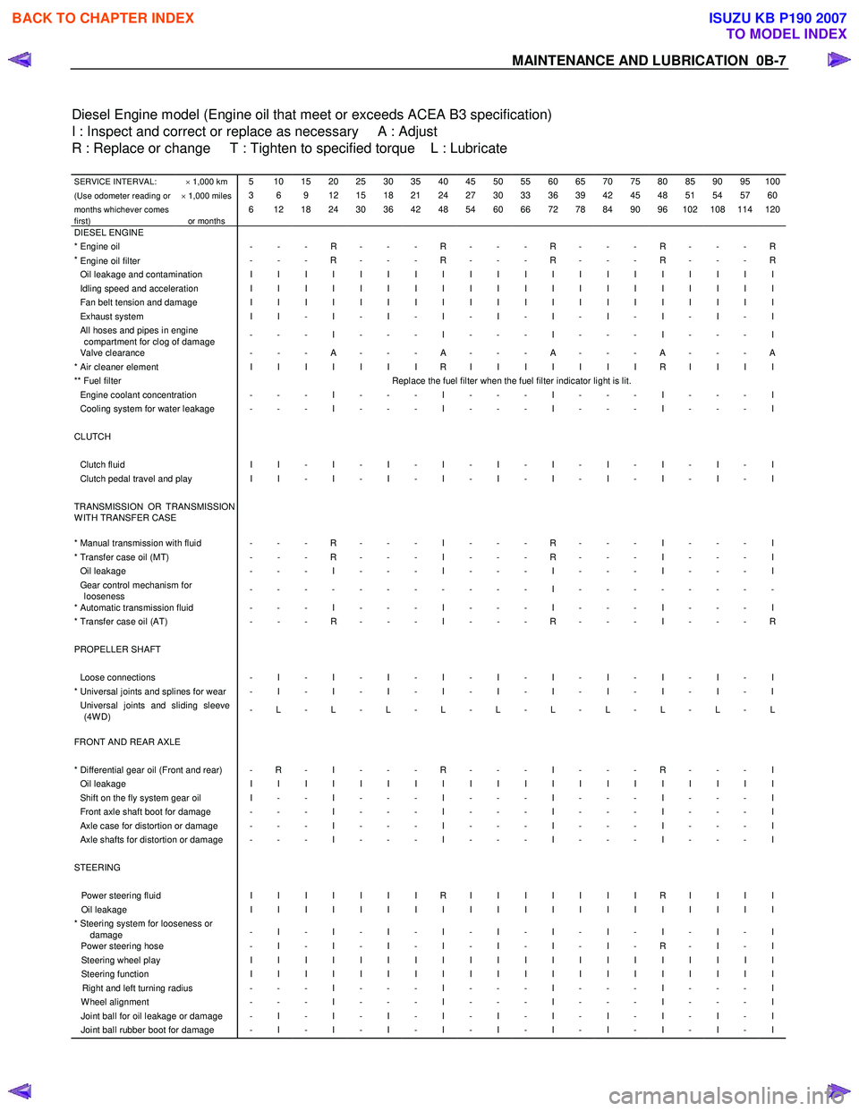
Diesel Engine model (Engine oil that meet or exceeds ACEA B3 specification)
I : Inspect and correct or replace as necessary A : Adjust
R : Replace or change T : Tighten to specified torque L : Lubricate
SERVICE INTERVAL: × 1,000 km 5 10 15 20 25 30 35 40 45 50 55 60 65 70 75 80 85 90 95 100
(Use odometer reading or × 1,000 miles 3 6 9 12 15 18 21 24 27 30 33 36 39 42 45 48 51 54 57 60
months whichever comes
first)
or months 6 12 18 24 30 36 42 48 54 60 66 72 78 84 90 96 102 108 114 120
DIESEL ENGINE * Engine oil - - - R - - - R - - - R - - - R - - - R*
Engine oil filter
- - - R - - - R - - - R - - - R - - - R
Oil leakage and contamination I I I I I I I I I I I I I I I I I I I I Idling speed and acceleration I I I I I I I I I I I I I I I I I I I I Fan belt tension and damage I I I I I I I I I I I I I I I I I I I I Exhaust system I I - I - I - I - I - I - I - I - I - I All hoses and pipes in engine
compartment for clog of damage - - - I - - - I - - - I - - - I - - - I
Valve clearance
- - - A - - - A - - - A - - - A - - - A * Air cleaner element I I I I I I I R I I I I I I I R I I I I ** Fuel filter Replace the fuel filter when the fuel filter indicator light is lit. Engine coolant concentration - - - I - - - I - - - I - - - I - - - I Cooling system for water leakage - - - I - - - I - - - I - - - I - - - I CLUTCH Clutch fluid I I - I - I - I - I - I - I - I - I - I Clutch pedal travel and play I I - I - I - I - I - I - I - I - I - I TRANSMISSION OR TRANSMISSION
W ITH TRANSFER CASE
* Manual transmission with fluid - - - R - - - I - - - R - - - I - - - I * Transfer case oil (MT) - - - R - - - I - - - R - - - I - - - I Oil leakage - - - I - - - I - - - I - - - I - - - I Gear control mechanism for
looseness - - - - - - - - - - - I - - - - - - - -
* Automatic transmission fluid - - - I - - - I - - - I - - - I - - - I * Transfer case oil (AT)
- - - R - - - I - - - R - - - I - - - R PROPELLER SHAFT Loose connections - I - I - I - I - I - I - I - I - I - I * Universal joints and splines for wear - I - I - I - I - I - I - I - I - I - I Universal joints and sliding sleeve
(4W D) - L - L - L - L - L - L - L - L - L - L
FRONT AND REAR AXLE
* Differential gear oil (Front and rear) - R - I - - - R - - - I - - - R - - - I Oil leakage I I I I I I I I I I I I I I I I I I I I Shift on the fly system gear oil I - - I - - - I - - - I - - - I - - - I Front axle shaft boot for damage - - - I - - - I - - - I - - - I - - - I Axle case for distortion or damage - - - I - - - I - - - I - - - I - - - I Axle shafts for distortion or damage - - - I - - - I - - - I - - - I - - - I STEERING Power steering fluid I I I I I I I R I I I I I I I R I I I I Oil leakage I I I I I I I I I I I I I I I I I I I I * Steering system for looseness or
damage - I - I - I - I - I - I - I - I - I - I
Power steering hose
- I - I - I - I - I - I - I - R - I - I Steering wheel play I I I I I I I I I I I I I I I I I I I I Steering function I I I I I I I I I I I I I I I I I I I I Right and left turning radius - - - I - - - I - - - I - - - I - - - I W heel alignment - - - I - - - I - - - I - - - I - - - I Joint ball for oil leakage or damage - I - I - I - I - I - I - I - I - I - I Joint ball rubber boot for damage - I - I - I - I - I - I - I - I - I - I
BACK TO CHAPTER INDEX
TO MODEL INDEX
ISUZU KB P190 2007
Page 67 of 6020

HEATER AND AIR CONDITIONING 1-33
RECOVERY, RECYCLING, EVACUATION
AND CHARGING
Handling Refrigerant-134a (HFC-134a)
Air conditioning systems contain HFC-134a.
This is a chemical mixture, which requires special handling
procedures to avoid personal injury.
• Always wear safety goggles and protective gloves.
• Always work in a well-ventilated area. Do not weld or steam
clean on or near any vehicle-installed air conditioning lines
or components.
• If HFC-134a should come in contact with any part of the
body, flush the exposed area with cold water and
immediately seek medical help.
• If it is necessary to transport or carry any container of HFC-
134a in a vehicle, do not carry it in the passenger
compartment.
• If it is necessary to fill a small HFC-134a container from a
large one, never fill the container completely. Space should
always be allowed above the liquid for expansion.
• Keep HFC-134a containers stored below 40 °C (104 °F).
WARNING
•
••
•
SHOULD HFC-134a CONTACT YOUR EYE(S), CONSULT
A DOCTOR IMMEDIATELY.
•
••
•
DO NOT RUB THE AFFECTED EYE(S). INSTEAD,
SPLASH QUANTITIES OF FRESH COLD WATER OVER
THE AFFECTED AREA TO GRADUALLY RAISE THE
TEMPERATURE OF THE REFRIGERANT ABOVE THE
FREEZING POINT.
•
••
•
OBTAIN PROPER MEDICAL TREATMENT AS SOON AS
POSSIBLE. SHOULD THE HFC-134a TOUCH THE SKIN,
THE INJURY MUST BE TREATED THE SAME AS SKIN
WHICH HAS BEEN FROSTBITTEN OR FROZEN.
F06R300012
REFRIGERANT RECOVERY
The refrigerant must be discharged and recovered by using
ACR4 (HFC-134a Refrigerant Recovery/Recycling/Recharging/
System) or equivalent before removing or installing air
conditioning parts.
ACR
4 (115V 60Hz) :5-8840-0629-0 (J-39500-A)
ACR4 (220-240V 50/60Hz)
: 5-8840-0630-0 (J-39500-220A)
ACR
4 (220-240V 50/60Hz Australian model)
: 5-8840-0631-0 (J-39500-220ANZ)
1) Connect the high and low charging hoses of the ACR
4 (or
equivalent) as shown.
2) Recover the refrigerant by following the ACR
4
Manufacturer's Instructions.
3) W hen a part is removed, put a cap or a plug on the connecting portion so that dust, dirt or moisture cannot get
into it.
BACK TO CHAPTER INDEX
TO MODEL INDEX
ISUZU KB P190 2007
Page 85 of 6020
HEATER AND AIR CONDITIONING 1-51
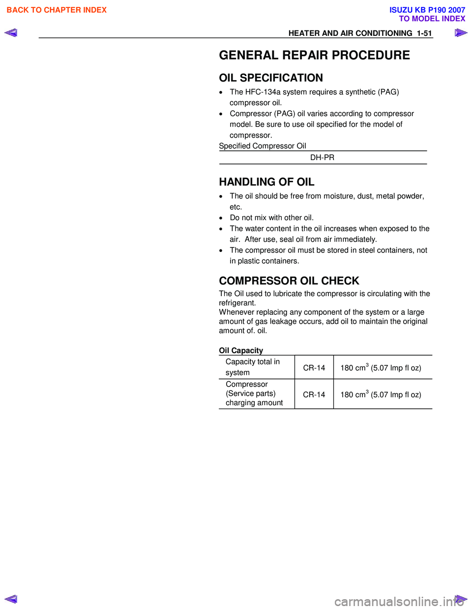
GENERAL REPAIR PROCEDURE
OIL SPECIFICATION
•
The HFC-134a system requires a synthetic (PAG)
compressor oil.
• Compressor (PAG) oil varies according to compressor
model. Be sure to use oil specified for the model of
compressor.
Specified Compressor Oil
DH-PR
HANDLING OF OIL
•
The oil should be free from moisture, dust, metal powder,
etc.
• Do not mix with other oil.
• The water content in the oil increases when exposed to the
air. After use, seal oil from air immediately.
• The compressor oil must be stored in steel containers, not
in plastic containers.
COMPRESSOR OIL CHECK
The Oil used to lubricate the compressor is circulating with the
refrigerant.
W henever replacing any component of the system or a large
amount of gas leakage occurs, add oil to maintain the original
amount of. oil.
Oil Capacity
Capacity total in
system CR-14 180 cm
3 (5.07 lmp fl oz)
Compressor
(Service parts)
charging amount
CR-14
180 cm3 (5.07 lmp fl oz)
BACK TO CHAPTER INDEX
TO MODEL INDEX
ISUZU KB P190 2007
Page 125 of 6020

HEATER AND AIR CONDITIONING 1-91
RESULT SYMPTOM TROUBLE CAUSE CORRECTION
Reduced or no air flow through
the condenser
•
Condenser clogged or dirty
• Radiator (condenser) fan
does not operate properly •
Clean
• Check cooling fan
operation
No bubbles in sight glass when
condenser is cooled by water
(Insufficient cooling)
•
Excessive refrigerant in
system
•
Check sight glass.
(See “Reading Sight
Glass”)
• Discharge and
recover refrigerant.
Recharge to specified
amount
Discharge
(High)
pressure
gauge
abnormally
high
After stopping air conditioning,
pressure drops approx. 196 kPa
(2.0kg/cm
2 / 28psi) quickly •
Air in system
•
Evacuate and charge
refrigerant system
Insufficient cooling and excessive
bubbles in the sight glass
•
Insufficient refrigerant in
system
•
Check sight glass.
(See “Reading Sight
Glass”)
• Check for leaks
• Discharge and
recover refrigerant.
Recharge to specified
amount
Low pressure gauge indicates
vacuum •
Clogged or defective
expansion valve •
Replace the
expansion valve
Frost or dew on refrigerant line
before and after receiver/ drier or
expansion valve, and low pres-
sure gauge indicates vacuum •
Restriction caused by debris
or moisture in receiver/drier
•
Check system for
restriction and
replace receiver/drier
Discharge
(High)
pressure
gauge
abnormally
low
After turning off air conditioning,
high and low pressure gauge
balanced quickly
•
Compressor seal defective
• Poor compression due to
defective compressor
gasket •
Replace or repair
compressor
Low pressure gauge is lowered
after condenser is cooled by
water
•
Excessive refrigerant in
system
•
Discharge and
recover refrigerant
Recharge to specified
amount
Low pressure hose temperature
around the compressor refrigerant
line connector is lower than
around evaporator
•
Unsatisfactory valve
operation due to defective
temperature sensor of
expansion valve
• Expansion valve opens too
long •
Replace the
expansion valve
After turning off air conditioning,
high and low pressure gauge is
balanced quickly •
Compressor gasket is
defective
•
Replace
Suction
(Low)
pressure
gauge
abnormally
high
Air conditioning turns off before
passenger compartment is
sufficiently
cool •
Electronic thermostat
defective
•
Check the electronic
thermostat and
replace as necessary
* For the charging and discharging operations in the table above, refer to “RECOVERY, RECYCLING,
EVACUATION AND CHARGING” in this section.
BACK TO CHAPTER INDEX
TO MODEL INDEX
ISUZU KB P190 2007
Page 126 of 6020

1-92 HEATER AND AIR CONDITIONING
RESULT SYMPTOM TROUBLE CAUSE CORRECTION
Condenser is not hot and
excessive bubble in sight glass
•
Insufficient refrigerant
•
Check sight
glass.(See “Reading
Sight Glass”)
• Check for leaks
• Discharge and
recover refrigerant.
Recharge to specified
amount
Frost on the expansion valve inlet
line •
Expansion valve clogged
•
Replace the
expansion valve
A distinct difference in
temperature between the inlet and
outlet refrigerant lines of the
receiver/drier •
Receiver/drier clogged
•
Replace the receiver/
drier
Expansion valve outlet refrigerant
line is not cold and low-pressure
gauge indicates vacuum
•
The temperature sensor of
the expansion valve is
defective, and the valve
cannot regulate the correct
flow of the refrigerant •
Replace the
expansion valve
Discharge temperature is low and
air flow from vents is restricted
•
Frozen evaporator core fins
•
Check electronic
thermostat and
replace as necessary
Suction
(Low)
pressure
abnormally
low
Low-pressure gauge reading is
low, or a vacuum reading may be
shown •
Clogged or blocked
refrigerant line
•
Replace refrigerant
line
No bubbles in sight glass after
condenser is cooled by water
(Insufficient cooling)
•
Excessive refrigerant in
system
•
Check sight
glass.(See “Reading
Sight Glass”)
• Discharge and
recover refrigerant.
Recharge to specified
amount
Reduce air flow through con-
denser
•
Condenser clogged
• Radiator (condenser) fan
does not rotate properly •
Clean
• Check cooling fan
operation
Suction
(Low) and
Discharge
(High)
pressure
abnor-
mally
high
Suction (Low) pressure hose is
not cold •
Air in system • Evacuate and charge
refrigerant
Suction
(Low) and
Discharge
(High)
pres-sure
abnor-
mally
low Insufficient cooling and excessive
bubbles in the sight glass •
Insufficient refrigerant in
system
•
Check sight glass.
(See “Reading Sight
Glass”)
• Check for leaks
• Discharge and
recover refrigerant.
Recharge to specified
amount
BACK TO CHAPTER INDEX
TO MODEL INDEX
ISUZU KB P190 2007
Page 288 of 6020

POWER-ASSISTED STEERING SYSTEM 3B-27
Supplemental Restraint System Steering Wheel & Column
Service Precaution
This steering wheel and column repair section covers
the Supplemental Restraint System (SRS) steering
column. The following repair procedures are specific to
SRS components. W hen servicing a vehicle equipped
with Supplemental Restraint System, pay close attention
to all W ARNINGS and CAUTIONS.
For detailed explanation about SRS, refer to Restraints
section.
WARNING: THIS VEHICLE HAS A SUPPLEMENTAL
RESTRAINT SYSTEM (SRS). REFER TO THE SRS
COMPONENT AND WIRING LOCATION VIEW IN
ORDER TO DETERMINE WHETHER YOU ARE
PERFORMING SERVICE ON OR NEAR THE SRS
COMPONENTS OR THE SRS WIRING. WHEN YOU
ARE PERFORMING SERVICE ON OR NEAR THE
SRS COMPONENTS OR THE SRS WIRING, REFER
TO THE SRS SERVICE INFORMATION. FAILURE TO
FOLLOW WARNINGS COULD RESULT IN POSSIBLE
AIR BAG DEPLOYMENT, PERSONAL INJURY, OR
OTHERWISE UNNECESSARY SRS SYSTEM
REPAIRS.
SAFE HANDLING OF INFLATOR MODULES
REQUIRES THE PROCEDURES DESCRIBED
BELOW TO BE FOLLOWED FOR BOTH LIVE AND
DEPLOYED MODULES.
SAFETY PRECAUTIONS MUST BE FOLLOWED
WHEN HANDLING A DEPLOYED AIR BAG
ASSEMBLY (AIR BAG). AFTER DEPLOYMENT, THE
AIR BAG ASSEMBLY (AIR BAG) SURFACE MAY
CONTAIN A SMALL AMOUNT OF SODIUM
HYDROXIDE, A BY-PRODUCT OF THE
DEPLOYMENT REACTION, THAT IS IRRITATING TO
THE SKIN AND EYES. MOST OF THE POWDER ON
THE AIR BAG ASSEMBLY (AIR BAG) IS HARMLESS.
AS A PRECAUTION, WEAR GLOVES AND SAFETY
GLASSES WHEN HANDLING A DEPLO
YED AIR BAG
ASSEMBLY, AND WASH YOUR HANDS WITH MILD
SOAP AND WATER AFTERWARDS.
WHEN CARRYING A LIVE AIR BAG ASSEMBLY,
MAKE SURE THE BAG AND TRIM COVER ARE
POINTED AWAY FROM YOU. NEVER CARRY AN AIR
BAG ASSEMBLY BY THE WIRES OR CONNECTOR
ON THE UNDERSIDE OF MODULE. IN THE CASE OF
AN ACCIDENTAL DEPLOYMENT, THE BAG WILL
THEN DEPLOY WITH MINIMAL CHANCE OF INJURY.
WHEN PLACING A LIVE AIR BAG ASSEMBLY ON
A
BENCH OR OTHER SURFACE, ALWAYS FACE THE
BAG AND TRIM COVER UP, AWAY FROM THE
SURFACE.
NEVER REST A STEERING COLUMN ASSEMBLY
ON THE STEERING WHEEL WITH THE AIR BAG
ASSEMBLY FACE DOWN AND COLUMN VERTICAL.
THIS IS NECESSARY SO THAT A FREE SPACE IS
PROVIDED TO ALLOW THE AIR BAG ASSEMBLY
TO EXPAND IN THE UNLIKELY EVENT OF
ACCIDENTAL DEPLOYMENT. OTHERWISE,
PERSONAL INJURY COULD RESULT.
TO AVOID DEPLOYMENT WHEN
TROUBLESHOOTING THE SRS SYSTEM, DO NOT
USE ELECTRICAL TEST EQUIPMENT, SUCH AS
A
BATTERY-POWERED OR A/C-POWERED VOLT-
METER, OHMMETER, ETC., OR ANY TYPE OF
ELECTRICAL EQUIPMENT OTHER THAN SPECIFIED
IN THIS MANUAL. DO NOT USE A NON-POWERED
PROBE-TYPE TESTER.
INSTRUCTIONS IN THIS MANUAL MUST BE
FOLLOWED CAREFULLY, OTHERWISE PERSONAL
INJURY MAY RESULT.
SRS Connectors
CAUTION: The special yellow color connectors are
used for the supplemental restraint system-air bag
circuit.
When removing the cable harness, do not pull the
cables. Otherwise, cable disconnection may occur.
When connecting the SRS connector, insert the
connector completely. Imperfect locking may cause
malfunction of the SRS circuit.
BACK TO CHAPTER INDEX
TO MODEL INDEX
ISUZU KB P190 2007