2007 ISUZU KB P190 4jk1 sensor plugs
[x] Cancel search: 4jk1 sensor plugsPage 1365 of 6020
ENGINE MECHANICAL (4JK1/4JJ1) 6A-5
EGR system
Based upon data, including water temperature, engine
speeds or engine loads, it is controlled via Engine
Control Module (ECM) to purify exhaust by recycling
part of it.
Its main components include an EGR valve, an EGR
cooler and various sensors.
Connecting rod cap bolt
The angular tightening method of the connecting rod
cap bolt further increases reliability and durability.
Fuel rail-type electronic control injection system
The fuel rail-type electronic control injection system is
composed of a fuel supply pump that sets the target
pressure of high-pressure fuel and supply it, a fuel rail
that measures such high-pressure fuel and a fuel
injector that turns it into a fine spray and injects it. Each
is controlled via ECM based upon various signals, while
injection timing or fuel injection quantity is controlled
under every possible driving condition.
Fuel injector
The fuel injector is a 6-hole nozzle that adjusts fuel
injection quantity or injection timing by opening o
r
closing an electromagnetic valve on the head of the fuel
injector.
ECM corrects the dispersion of fuel injection quantit
y
between fuel injector according to ID code data in
memory. At the replacement of fuel injector, ID code
data should be stored in ECM.
Fuel filter with sedimenter
It is a fuel filter with sedimenter that gets rid of water by
making use of the difference in specific gravity between
light oil and water, which comes with an indicator that
notifies you that it is filled with water.
Preheating system
The preheating system consists of the ECM, the glow
relay, glow plugs and the glow indicator lamp. The
preheating system is operated when the engine coolant
temperature is low, and makes the engine easy to start.
Lubrication system
It is an oil filter with full-flow bypass, which uses a
water-cool oil cooler and oil jet to cool the piston.
Functional inspection
Inspection/adjustment of valve clearance 1. Inspection of valve clearance
• Remove the fuel injector harness assembly.
• Remove the leak off hose.
• Remove the cylinder head cover.
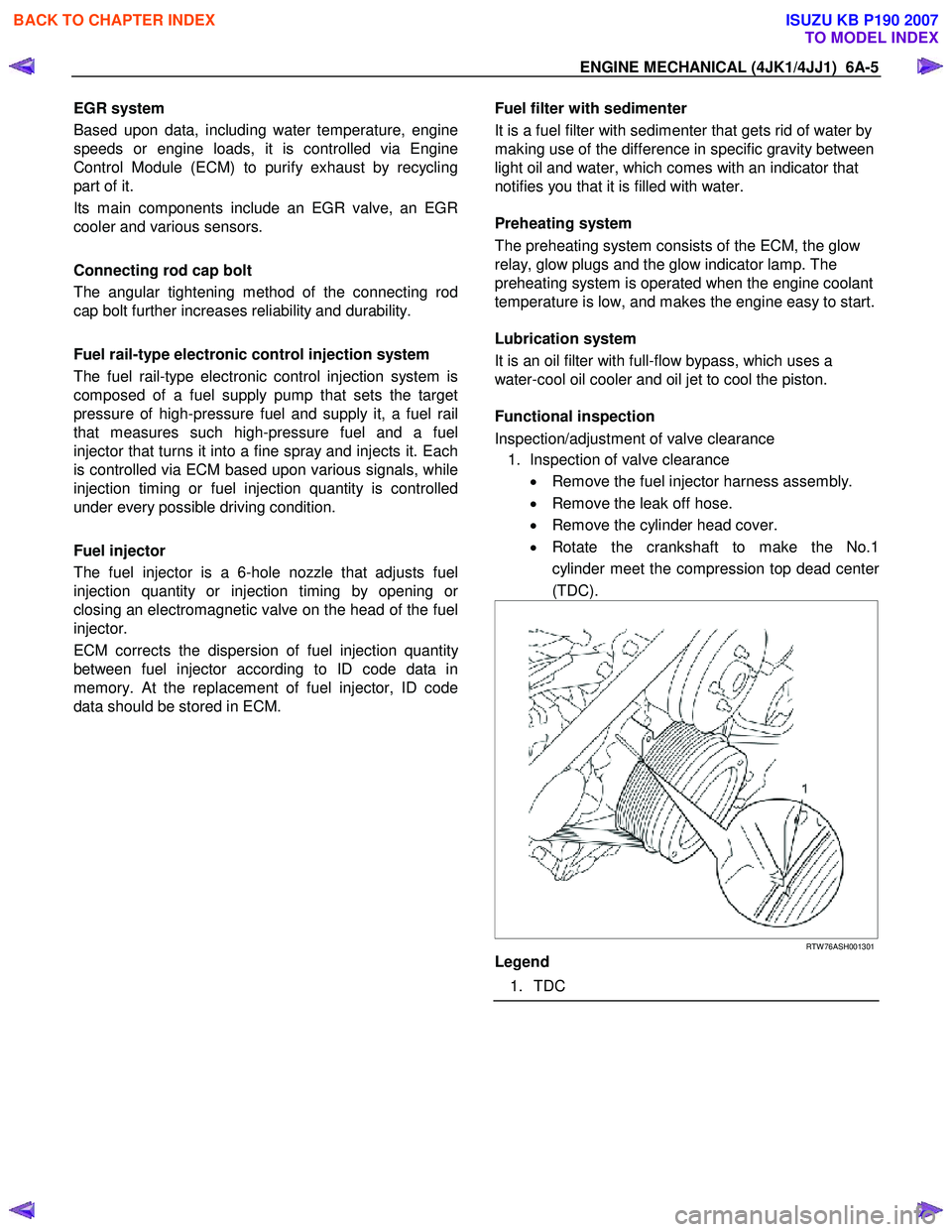
• Rotate the crankshaft to make the No.1
cylinder meet the compression top dead cente
r
(TDC).
RTW 76ASH001301
Legend
1. TDC
BACK TO CHAPTER INDEX
TO MODEL INDEX
ISUZU KB P190 2007
Page 1670 of 6020
ENGINE CONTROL SYSTEM (4JK1/4JJ1) 6E-53
Cam/ Crank Sensor Signal/ Synchronization Status
This parameter displays the synchronization state of
the crankshaft position (CKP) sensor signal and
camshaft position (CMP) sensor signal. Asynchronous
indicates the CMP sensor signal is not detected or only
CKP sensor signal is detected. No Crank Signal
indicates CMP sensor signal is detected but CKP
sensor signal is not detected. Synchronous indicates
both sensor signals are detected correctly.
Engine Runtime
This parameter displays the time elapsed since the
engine start. The scan tool will display the time in
hours, minutes and seconds. The engine run time will
reset to zero as soon as the ignition switch is OFF.
Vehicle Speed
This parameter indicates the vehicle speed calculated
by the ECM using the signal from the vehicle speed
sensor (VSS). The scan tool will display a low value at
lower vehicle speeds, and a high value at higher
vehicle speeds.
Transmission Gear
This parameter displays the estimated transmission
gear position as calculated by the ECM based on
inputs from the vehicle speed and the engine speed.
Starter Switch
This parameter displays the input status of the starter
switch to the ECM. When the ignition switch is turned at
START position, the scan tool displays On.
Ignition Switch
This parameter displays the input status of the ignition
switch to the ECM. When the ignition switch is turned
ON position, the scan tool displays On.
Ignition Voltage
This parameter displays the ignition voltage measured
at the ignition feed circuit of the ECM. Voltage is
applied to the ECM when the ignition switch is ON
position.
Battery Voltage
This parameter displays the battery voltage measured
at the ECM main relay switched voltage feed circuit of
the ECM. Voltage is applied to the ECM when the ECM
main relay is energized.
Fuel Pump Relay Command
This parameter displays the commanded state of the
fuel pump relay control circuit. On indicates the fuel
pump relay control circuit is being grounded by the
ECM, allowing fuel pumping from the tank.
Swirl Control Solenoid Command
This parameter displays the commanded state of the
swirl control solenoid control circuit. On indicates the
swirl control solenoid control circuit is being grounded
by the ECM, allowing vacuum pressure to the swirl
control
actuator. Fuel Filter Switch
This parameter displays the input state of the fuel
pressure switch to the ECM. When the large vacuum
pressure is generated in the fuel suction line such as
clogged fuel filter, the scan tool displays Off.
A/C Request Signal
This parameter displays the input state of the air
conditioning (A/C) request to the ECM from the
heating, ventilation, and air conditioning (HVAC)
controls. When the HVAC system is requesting to
ground the A/C compressor clutch, the scan tool
displays On.
A/C Relay Command
This parameter displays the commanded state of the A/
C compressor relay control circuit. On indicates the A/C
compressor relay control circuit is being grounded by
the ECM, allowing voltage to the A/C compressor.
Park/ Neutral Switch
This parameter displays the input state of the neutral
switch to the ECM. When the transmission gear is Park
or Neutral, the scan tool displays Neutral.
Glow Relay Command
This parameter displays the commanded state of the
glow relay control circuit. On indicates the glow relay
control circuit is being grounded by the ECM, allowing
voltage to the glow plugs.
Glow Plug Lamp Command
This parameter displays the commanded state of the
glow indicator lamp control circuit. The glow indicator
lamp should be On when the scan tool indicates
command On. The glow indicator lamp should be Off
when the scan tool indicates command Off.
Brake Switch 1
This parameter displays the input state of the brake
pedal switch 1 to the ECM. When the brake pedal is
depressed, scan tool displays Applied.
Brake Switch 2
This parameter displays the input state of the brake
pedal switch 2 to the ECM. When the brake pedal is
depressed, scan tool displays Applied.
Clutch Pedal Switch
This parameter displays the input state of the clutch
pedal switch to the ECM. When the clutch pedal is
depressed, scan tool displays Applied.
Cruise Main Lamp Command
This parameter displays the commanded state of the
cruise main lamp control circuit. The cruise main lamp
should be On when the scan tool indicates command
On. The cruise main lamp should be Off when the scan
tool indicates command Off.
Cruise Main Switch
This parameter displays the input state of the cruise
main switch to the ECM. When the Cruise Main switch
is pushed, the scan tool displays On.
BACK TO CHAPTER INDEX
TO MODEL INDEX
ISUZU KB P190 2007
Page 1775 of 6020
6E-158 ENGINE CONTROL SYSTEM (4JK1/4JJ1)
DTC P0380 (Flash Code 66)
Circuit Description
The ECM controls the glow relay which supplies power
to the glow plugs based on engine coolant
temperature. In the after glow phase, the glow indicator
light is not illuminated but glow plugs remain active for
a certain period. If the ECM detects an open circuit or
short circuit on the relay control circuit, this DTC will
set.
Condition for Running the DTC • The battery voltage is more than 9 volts.
• The ignition voltage is more than 9 volts.
• The ignition switch is ON.
Condition for Setting the DTC
Either of following condition is met: • The ECM detects a low voltage condition on the glow relay control circuit for longer than 3 second
when the relay is commanded OFF.
• The ECM detects a high voltage condition on the glow relay control circuit for longer than 3 second
when the relay is commanded ON.
Action Taken When the DTC Sets • The ECM illuminates the SVS lamp when the diagnostic runs and fails. Refer to DTC Type
Definitions for Action Taken When the DTC Sets -
Type C. (Euro 4 Specification) • The ECM illuminates the MIL when the diagnostic
runs and fails. Refer to DTC Type Definitions for
Action Taken When the DTC Sets - Type A.
(Except Euro 4 Specification)
Condition for Clearing the DTC • Refer to DTC Type Definitions for Condition for Clearing the SVS Lamp/ DTC - Type C. (Euro 4
Specification)
• Refer to DTC Type Definitions for Condition for Clearing the MIL/ DTC - Type A. (Except Euro 4
Specification)
Diagnostic Aids • If an intermittent condition is suspected, refer to Intermittent Conditions in this section.
Test Description
The numbers below refers to the step number on the
Circuit/ System Testing.
2. Listen for an audible click when the glow relay
operates. Command both the ON and OFF states.
Schematic Reference: Engine Controls Schematics
Connector End View Reference: Engine Controls
Connector End Views or ECM Connector End Views
Circuit/ System Testing DTC P0380
Step Action Value(s)Yes No
1 Did you perform the Diagnostic System Check -
Engine Controls? —
Go to Step 2 Go to Diagnostic
System Check -
Engine Controls
2 1. Install a scan tool.
2. Perform the Glow Relay Control with a scan tool.
3. Command the relay ON and OFF.
Does the glow relay click with each command? —
Go to Step 3 Go to Step 4
3 1. Turn OFF the ignition for 30 seconds.
2. Disconnect the engine coolant temperature (ECT) sensor harness connector in order to
gain glow ON time long enough.
3. Turn ON the ignition for 30 seconds while observing the DTC Information with a scan
tool.
Does the DTC P0380 fail this ignition? —
Go to Step 11 Go to Diagnostic
Aids
BACK TO CHAPTER INDEX
TO MODEL INDEX
ISUZU KB P190 2007