2007 ISUZU KB P190 ignition
[x] Cancel search: ignitionPage 2419 of 6020
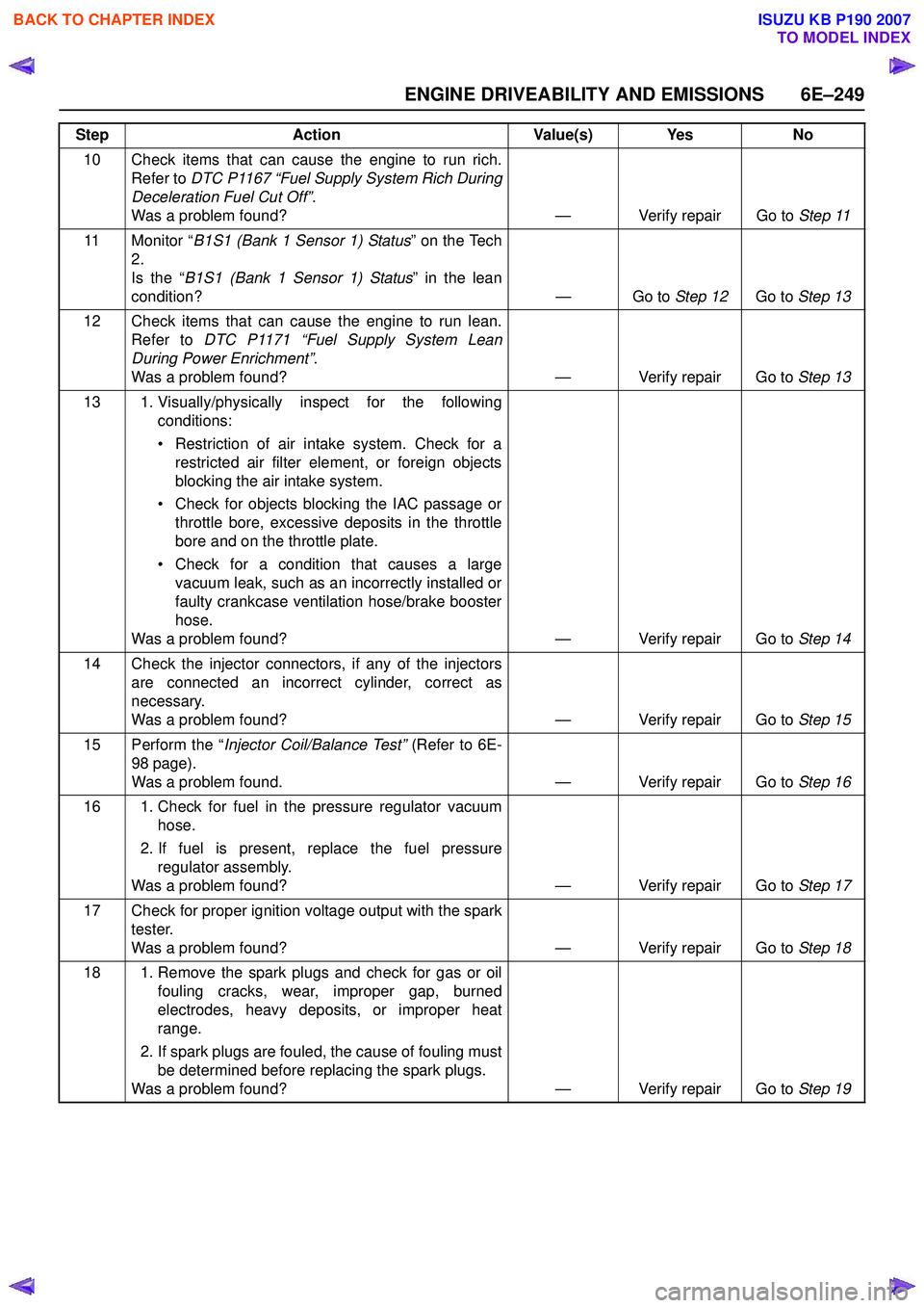
ENGINE DRIVEABILITY AND EMISSIONS 6E–249
10 Check items that can cause the engine to run rich.Refer to DTC P1167 “Fuel Supply System Rich During
Deceleration Fuel Cut Off” .
Was a problem found? — Verify repair Go to Step 11
11 Monitor “ B1S1 (Bank 1 Sensor 1) Status ” on the Tech
2.
Is the “ B1S1 (Bank 1 Sensor 1) Status ” in the lean
condition? — Go to Step 12Go to Step 13
12 Check items that can cause the engine to run lean. Refer to DTC P1171 “Fuel Supply System Lean
During Power Enrichment” .
Was a problem found? — Verify repair Go to Step 13
13 1. Visually/physically inspect for the following conditions:
• Restriction of air intake system. Check for a restricted air filter element, or foreign objects
blocking the air intake system.
• Check for objects blocking the IAC passage or throttle bore, excessive deposits in the throttle
bore and on the throttle plate.
• Check for a condition that causes a large vacuum leak, such as an incorrectly installed or
faulty crankcase ventilation hose/brake booster
hose.
Was a problem found? — Verify repair Go to Step 14
14 Check the injector connectors, if any of the injectors are connected an incorrect cylinder, correct as
necessary.
Was a problem found? — Verify repair Go to Step 15
15 Perform the “ Injector Coil/Balance Test” (Refer to 6E-
98 page).
Was a problem found. — Verify repair Go to Step 16
16 1. Check for fuel in the pressure regulator vacuum hose.
2. If fuel is present, replace the fuel pressure regulator assembly.
Was a problem found? — Verify repair Go to Step 17
17 Check for proper ignition voltage output with the spark tester.
Was a problem found? — Verify repair Go to Step 18
18 1. Remove the spark plugs and check for gas or oil fouling cracks, wear, improper gap, burned
electrodes, heavy deposits, or improper heat
range.
2. If spark plugs are fouled, the cause of fouling must be determined before replacing the spark plugs.
Was a problem found? — Verify repair Go to Step 19
Step
Action Value(s) Yes No
BACK TO CHAPTER INDEX
TO MODEL INDEX
ISUZU KB P190 2007
Page 2422 of 6020
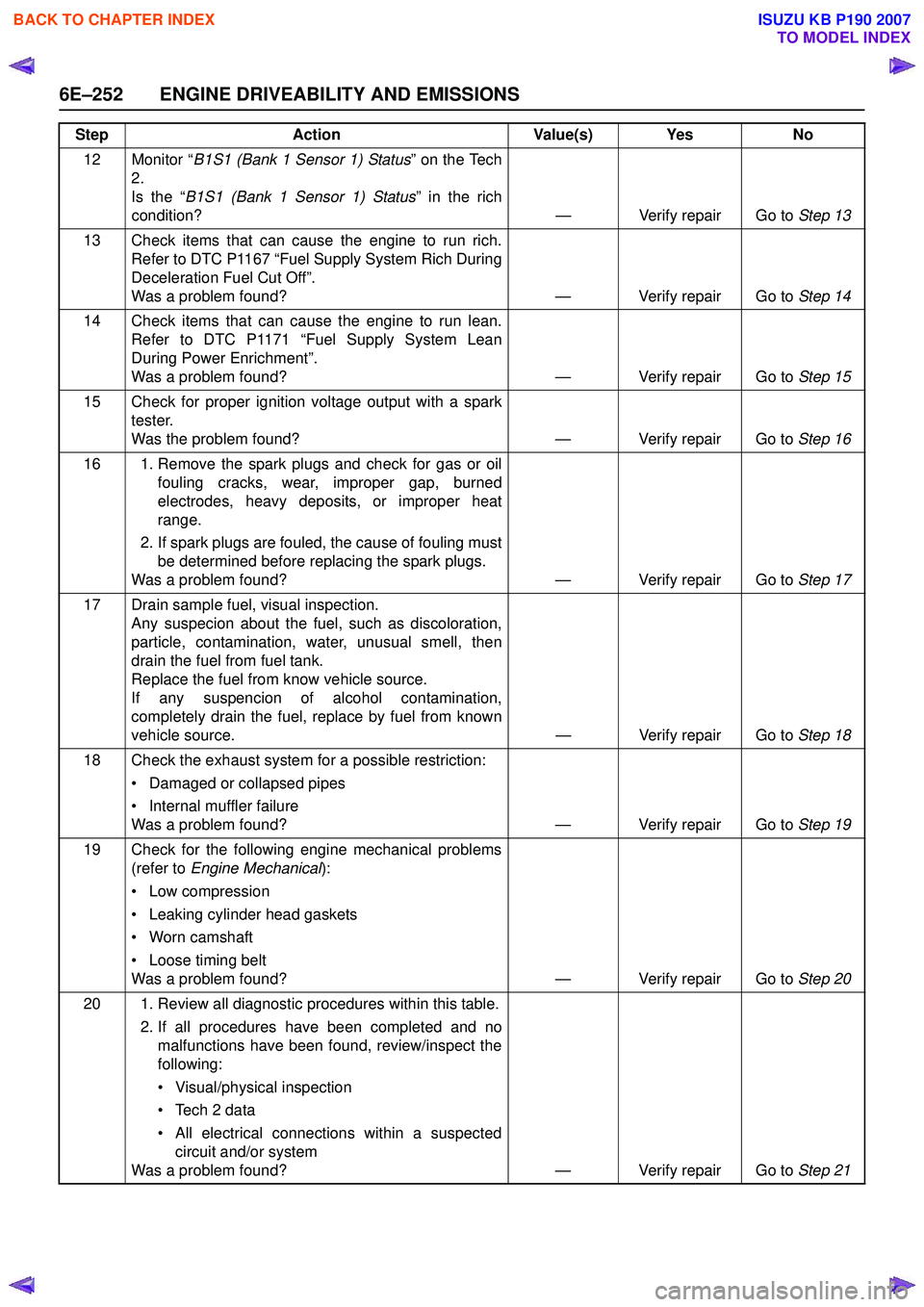
6E–252 ENGINE DRIVEABILITY AND EMISSIONS
12 Monitor “B1S1 (Bank 1 Sensor 1) Status ” on the Tech
2.
Is the “ B1S1 (Bank 1 Sensor 1) Status ” in the rich
condition? — Verify repair Go to Step 13
13 Check items that can cause the engine to run rich. Refer to DTC P1167 “Fuel Supply System Rich During
Deceleration Fuel Cut Off”.
Was a problem found? — Verify repair Go to Step 14
14 Check items that can cause the engine to run lean. Refer to DTC P1171 “Fuel Supply System Lean
During Power Enrichment”.
Was a problem found? — Verify repair Go to Step 15
15 Check for proper ignition voltage output with a spark tester.
Was the problem found? — Verify repair Go to Step 16
16 1. Remove the spark plugs and check for gas or oil fouling cracks, wear, improper gap, burned
electrodes, heavy deposits, or improper heat
range.
2. If spark plugs are fouled, the cause of fouling must be determined before replacing the spark plugs.
Was a problem found? — Verify repair Go to Step 17
17 Drain sample fuel, visual inspection. Any suspecion about the fuel, such as discoloration,
particle, contamination, water, unusual smell, then
drain the fuel from fuel tank.
Replace the fuel from know vehicle source.
If any suspencion of alcohol contamination,
completely drain the fuel, replace by fuel from known
vehicle source. — Verify repair Go to Step 18
18 Check the exhaust system for a possible restriction: • Damaged or collapsed pipes
• Internal muffler failure
Was a problem found? — Verify repair Go to Step 19
19 Check for the following engine mechanical problems (refer to Engine Mechanical ):
• Low compression
• Leaking cylinder head gaskets
• Worn camshaft
• Loose timing belt
Was a problem found? — Verify repair Go to Step 20
20 1. Review all diagnostic procedures within this table. 2. If all procedures have been completed and nomalfunctions have been found, review/inspect the
following:
• Visual/physical inspection
• Tech 2 data
• All electrical connections within a suspected circuit and/or system
Was a problem found? — Verify repair Go to Step 21
Step
Action Value(s) Yes No
BACK TO CHAPTER INDEX
TO MODEL INDEX
ISUZU KB P190 2007
Page 2431 of 6020
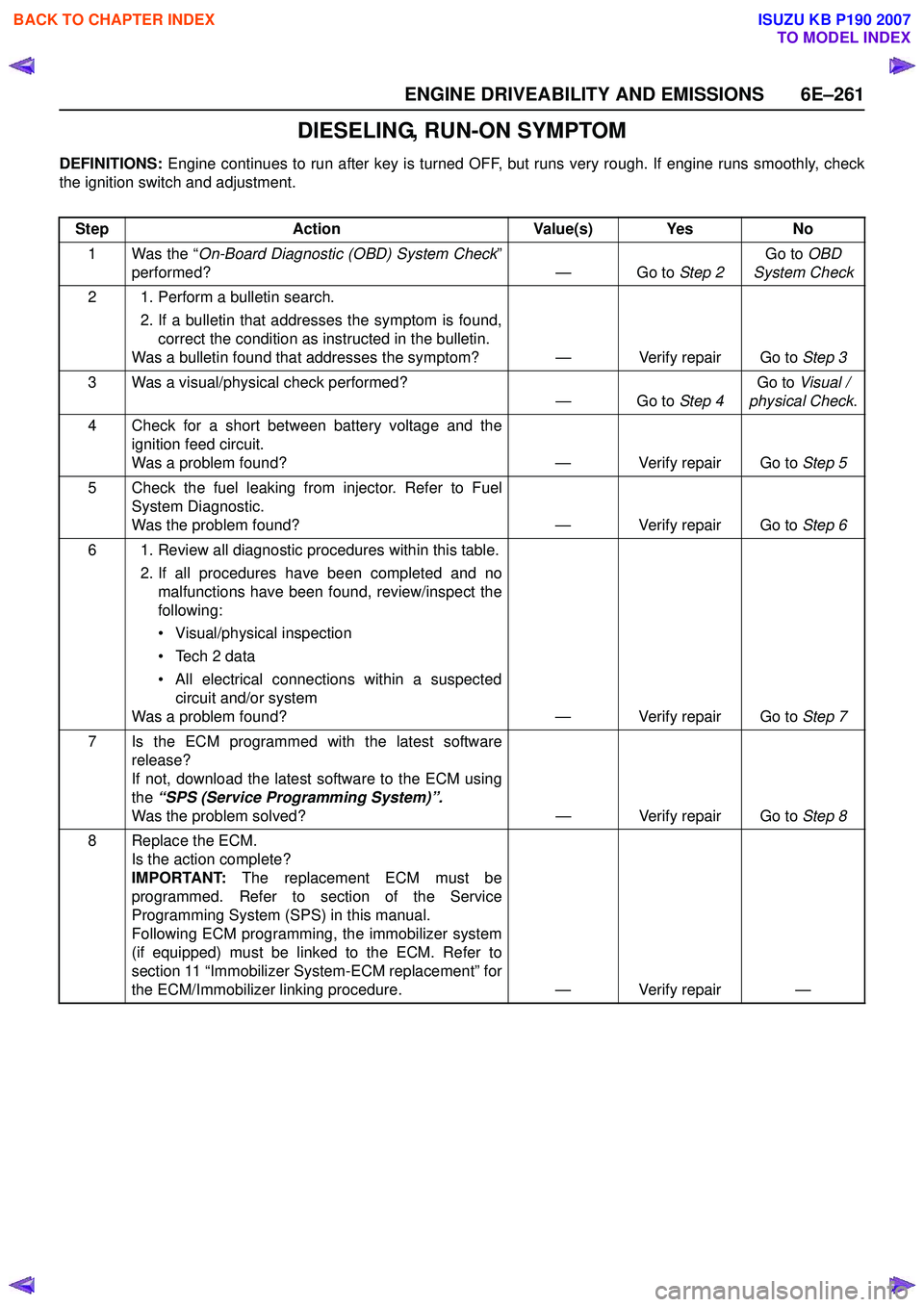
ENGINE DRIVEABILITY AND EMISSIONS 6E–261
DIESELING, RUN-ON SYMPTOM
DEFINITIONS: Engine continues to run after key is turned OFF, but runs very rough. If engine runs smoothly, check
the ignition switch and adjustment.
Step Action Value(s) Yes No
1 Was the “ On-Board Diagnostic (OBD) System Check ”
performed? — Go to Step 2Go to
OBD
System Check
2 1. Perform a bulletin search. 2. If a bulletin that addresses the symptom is found,correct the condition as instructed in the bulletin.
Was a bulletin found that addresses the symptom? — Verify repair Go to Step 3
3 Was a visual/physical check performed? —Go to Step 4Go to
Visual /
physical Check .
4 Check for a short between battery voltage and the ignition feed circuit.
Was a problem found? — Verify repair Go to Step 5
5 Check the fuel leaking from injector. Refer to Fuel System Diagnostic.
Was the problem found? — Verify repair Go to Step 6
6 1. Review all diagnostic procedures within this table. 2. If all procedures have been completed and nomalfunctions have been found, review/inspect the
following:
• Visual/physical inspection
• Tech 2 data
• All electrical connections within a suspected circuit and/or system
Was a problem found? — Verify repair Go to Step 7
7 Is the ECM programmed with the latest software release?
If not, download the latest software to the ECM using
the “SPS (Service Programming System)”.
Was the problem solved? — Verify repair Go to Step 8
8 Replace the ECM. Is the action complete?
IMPORTANT: The replacement ECM must be
programmed. Refer to section of the Service
Programming System (SPS) in this manual.
Following ECM programming, the immobilizer system
(if equipped) must be linked to the ECM. Refer to
section 11 “Immobilizer System-ECM replacement” for
the ECM/Immobilizer linking procedure. — Verify repair —
BACK TO CHAPTER INDEX
TO MODEL INDEX
ISUZU KB P190 2007
Page 2432 of 6020
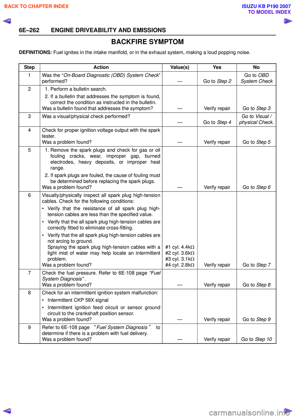
6E–262 ENGINE DRIVEABILITY AND EMISSIONS
BACKFIRE SYMPTOM
DEFINITIONS: Fuel ignites in the intake manifold, or in the exhaust system, making a loud popping noise.
Step Action Value(s) Yes No
1 Was the “ On-Board Diagnostic (OBD) System Check ”
performed? — Go to Step 2Go to
OBD
System Check
2 1. Perform a bulletin search. 2. If a bulletin that addresses the symptom is found,correct the condition as instructed in the bulletin.
Was a bulletin found that addresses the symptom? — Verify repair Go to Step 3
3 Was a visual/physical check performed? —Go to Step 4Go to
Visual /
physical Check .
4 Check for proper ignition voltage output with the spark tester.
Was a problem found? — Verify repair Go to Step 5
5 1. Remove the spark plugs and check for gas or oil fouling cracks, wear, improper gap, burned
electrodes, heavy deposits, or improper heat
range.
2. If spark plugs are fouled, the cause of fouling must be determined before replacing the spark plugs.
Was a problem found? — Verify repair Go to Step 6
6 Visually/physically inspect all spark plug high-tension cables. Check for the following conditions:
• Verify that the resistance of all spark plug high- tension cables are less than the specified value.
• Verify that the all spark plug high-tension cables are correctly fitted to eliminate cross-fitting.
• Verify that the all spark plug high-tension cables are not arcing to ground.
Spraying the spark plug high-tension cables with a
light mist of water may help locate an intermittent
problem.
Was a problem found? #1 cyl. 4.4k
Ω
#2 cyl. 3.6k Ω
#3 cyl. 3.1k Ω
#4 cyl. 2.8k ΩVerify repair Go to Step 7
7 Check the fuel pressure. Refer to 6E-108 page “Fuel
System Diagnosis” .
Was a problem found? — Verify repair Go to Step 8
8 Check for an intermittent ignition system malfunction: • Intermittent CKP 58X signal
• Intermittent ignition feed circuit or sensor ground circuit to the crankshaft position sensor.
Was a problem found? — Verify repair Go to Step 9
9 Refer to 6E-108 page “Fuel System Diagnosis ” to
determine if there is a problem with fuel delivery.
Was a problem found? — Verify repair Go to Step 10
BACK TO CHAPTER INDEX
TO MODEL INDEX
ISUZU KB P190 2007
Page 2445 of 6020
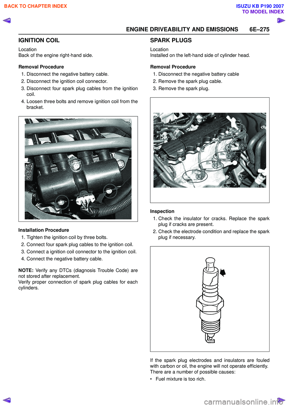
ENGINE DRIVEABILITY AND EMISSIONS 6E–275
IGNITION COIL
Location
Back of the engine right-hand side.
Removal Procedure 1. Disconnect the negative battery cable.
2. Disconnect the ignition coil connector.
3. Disconnect four spark plug cables from the ignition coil.
4. Loosen three bolts and remove ignition coil from the bracket.
Installation Procedure 1. Tighten the ignition coil by three bolts.
2. Connect four spark plug cables to the ignition coil.
3. Connect a ignition coil connector to the ignition coil.
4. Connect the negative battery cable.
NOTE: Verify any DTCs (diagnosis Trouble Code) are
not stored after replacement.
Verify proper connection of spark plug cables for each
cylinders.
SPARK PLUGS
Location
Installed on the left-hand side of cylinder head.
Removal Procedure 1. Disconnect the negative battery cable
2. Remove the spark plug cable.
3. Remove the spark plug.
Inspection 1. Check the insulator for cracks. Replace the spark plug if cracks are present.
2. Check the electrode condition and replace the spark plug if necessary.
If the spark plug electrodes and insulators are fouled
with carbon or oil, the engine will not operate efficiently.
There are a number of possible causes:
• Fuel mixture is too rich.
BACK TO CHAPTER INDEX
TO MODEL INDEX
ISUZU KB P190 2007
Page 2447 of 6020
ENGINE DRIVEABILITY AND EMISSIONS 6E–277
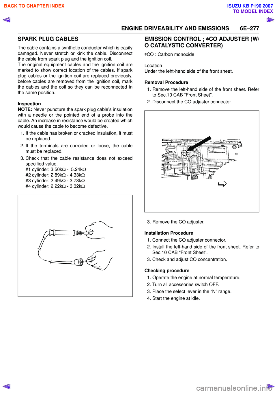
SPARK PLUG CABLES
The cable contains a synthetic conductor which is easily
damaged. Never stretch or kink the cable. Disconnect
the cable from spark plug and the ignition coil.
The original equipment cables and the ignition coil are
marked to show correct location of the cables. If spark
plug cables or the ignition coil are replaced previously,
before cables are removed from the ignition coil, mark
the cables and the coil so they can be reconnected in
the same position.
Inspection
NOTE: Never puncture the spark plug cable’s insulation
with a needle or the pointed end of a probe into the
cable. An increase in resistance would be created which
would cause the cable to become defective.
1. If the cable has broken or cracked insulation, it must be replaced.
2. If the terminals are corroded or loose, the cable must be replaced.
3. Check that the cable resistance does not exceed specified value.
#1 cylinder: 3.50k Ω - 5.24k Ω
#2 cylinder: 2.89k Ω - 4.33k Ω
#3 cylinder: 2.49k Ω - 3.73k Ω
#4 cylinder: 2.22k Ω - 3.32k Ω
EMISSION CONTROL ; *
**
*
CO ADJUSTER (W/
O CATALYSTIC CONVERTER)
* CO : Carbon monoxide
Location
Under the leht-hand side of the front sheet.
Removal Procedure 1. Remove the left-hand side of the front sheet. Refer to Sec.10 CAB “Front Sheet”.
2. Disconnect the CO adjuster connector.
3. Remove the CO adjuster.
Installation Procedure 1. Connect the CO adjuster connector.
2. Install the left-hand side of the front sheet. Refer to Sec.10 CAB “Front Sheet”.
3. Check and adjust CO concentration.
Checking procedure 1. Operate the engine at normal temperature.
2. Turn all accessories switch OFF.
3. Place the select lever in the “N” range.
4. Start the engine at idle.
BACK TO CHAPTER INDEX
TO MODEL INDEX
ISUZU KB P190 2007
Page 2489 of 6020
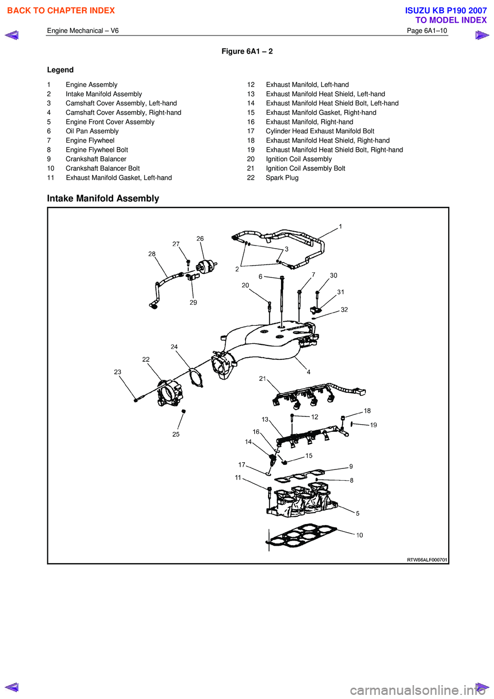
Engine Mechanical – V6 Page 6A1–10
Figure 6A1 – 2
Legend
1 Engine Assembly
2 Intake Manifold Assembly
3 Camshaft Cover Assembly, Left-hand
4 Camshaft Cover Assembly, Right-hand
5 Engine Front Cover Assembly
6 Oil Pan Assembly
7 Engine Flywheel
8 Engine Flywheel Bolt
9 Crankshaft Balancer
10 Crankshaft Balancer Bolt
11 Exhaust Manifold Gasket, Left-hand 12 Exhaust Manifold, Left-hand
13 Exhaust Manifold Heat Shield, Left-hand
14 Exhaust Manifold Heat Shield Bolt, Left-hand
15 Exhaust Manifold Gasket, Right-hand
16 Exhaust Manifold, Right-hand
17 Cylinder Head Exhaust Manifold Bolt
18 Exhaust Manifold Heat Shield, Right-hand
19 Exhaust Manifold Heat Shield Bolt, Right-hand
20 Ignition Coil Assembly
21 Ignition Coil Assembly Bolt
22 Spark Plug
Intake Manifold Assembly
BACK TO CHAPTER INDEX
TO MODEL INDEX
ISUZU KB P190 2007
Page 2493 of 6020
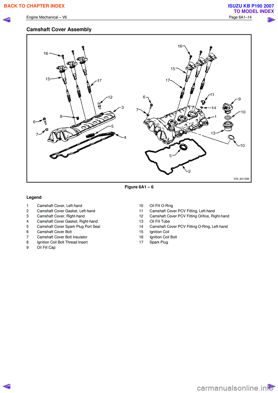
Engine Mechanical – V6 Page 6A1–14
Camshaft Cover Assembly
Figure 6A1 – 6
Legend
1 Camshaft Cover, Left-hand
2 Camshaft Cover Gasket, Left-hand
3 Camshaft Cover, Right-hand
4 Camshaft Cover Gasket, Right-hand
5 Camshaft Cover Spark Plug Port Seal
6 Camshaft Cover Bolt
7 Camshaft Cover Bolt Insulator
8 Ignition Coil Bolt Thread Insert
9 Oil Fill Cap 10 Oil Fill O-Ring
11 Camshaft Cover PCV Fitting, Left-hand
12 Camshaft Cover PCV Fitting Orifice, Right-hand
13 Oil Fill Tube
14 Camshaft Cover PCV Fitting O-Ring, Left-hand
15 Ignition Coil
16 Ignition Coil Bolt
17 Spark Plug
BACK TO CHAPTER INDEX
TO MODEL INDEX
ISUZU KB P190 2007