Page 2845 of 6020

Engine Mechanical – V6 Page 6A1–68
Page 6A1–68
Pressure Check
1 Run the engine to bring it to normal operating temperature.
2 Park the vehicle on a level surface. A vehicle not level will affect the accuracy of the level reading.
3 Stop the engine and wait 5 to 10 minutes to a llow the oil to drain back into the oil pan.
4 Check the oil level and top up with the recommended engine o il as required, refer to Check, in this Section.
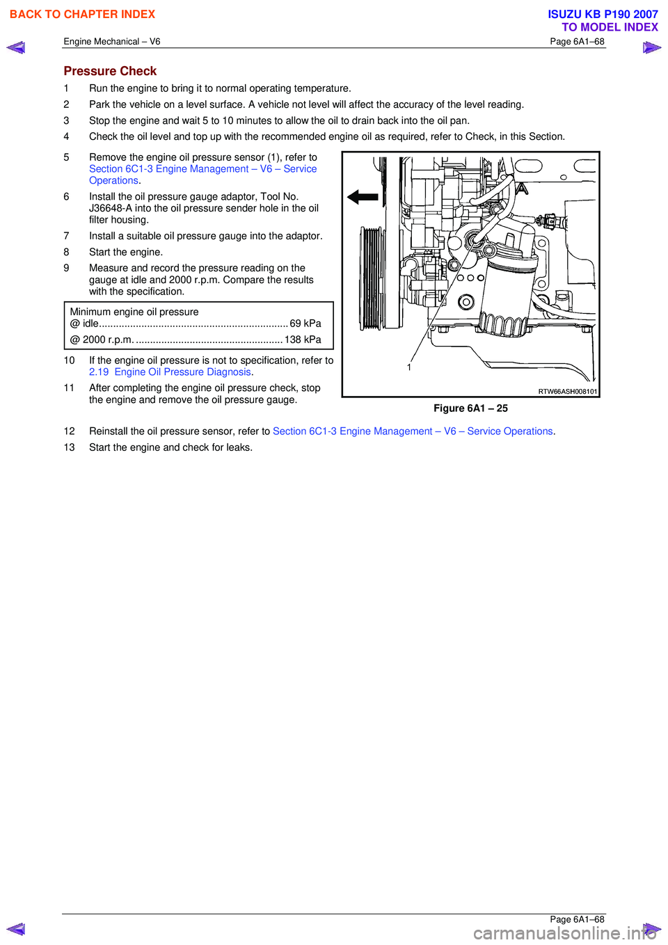
5 Remove the engine oil pressure sensor (1), refer to Section 6C1-3 Engine Management – V6 – Service
Operations .
6 Install the oil pressure gauge adaptor, Tool No. J36648-A into the oil pressure sender hole in the oil
filter housing.
7 Install a suitable oil pressure gauge into the adaptor.
8 Start the engine.
9 Measure and record the pressure reading on the gauge at idle and 2000 r.p.m. Compare the results
with the specification.
Minimum engine oil pressure
@ idle ................................................................... 69 kPa
@ 2000 r.p.m. .................................................... 138 kPa
10 If the engine oil pressure is not to specification, refer to
2.19 Engine Oil Pressure Diagnosis .
11 After completing the engine oil pressure check, stop the engine and remove the oil pressure gauge.
Figure 6A1 – 25
12 Reinstall the oil pressure sensor, refer to Section 6C1-3 Engine Management – V6 – Service Operations.
13 Start the engine and check for leaks.
BACK TO CHAPTER INDEX
TO MODEL INDEX
ISUZU KB P190 2007
Page 2867 of 6020
Engine Mechanical – V6 Page 6A1–90
Page 6A1–90
5 Ensure all wiring connectors are fully engaged and if applicable, locked in place.
6 Ensure all wiring harnesses are correctly routed and attached securely in their retaining clips.
7 Ensure that all hoses and pipes ar e routed correctly and that any retaining clips are correctly installed.
8 After installation pull on any quick connect fittings to check that each is correctly installed.
9 Start and run the engine to c heck for correct operation.
BACK TO CHAPTER INDEX
TO MODEL INDEX
ISUZU KB P190 2007
Page 2870 of 6020

Engine Mechanical – V6 Page 6A1–93
Page 6A1–93
Inspect
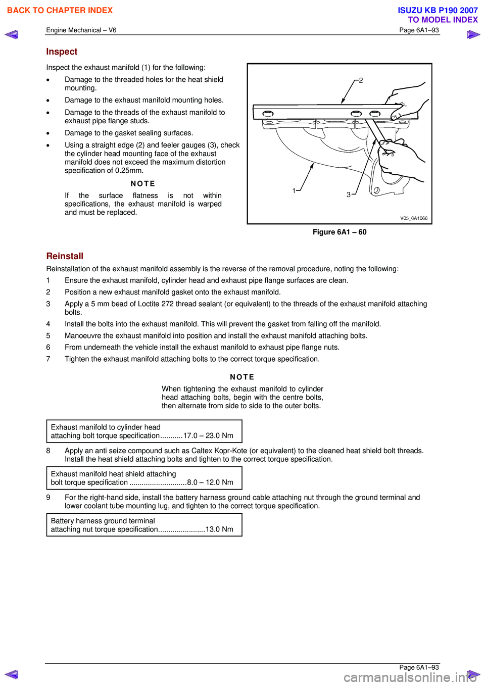
Inspect the exhaust manifold (1) for the following:
• Damage to the threaded holes for the heat shield
mounting.
• Damage to the exhaust manifold mounting holes.
• Damage to the threads of the exhaust manifold to
exhaust pipe flange studs.
• Damage to the gasket sealing surfaces.
• Using a straight edge (2) and feeler gauges (3), check
the cylinder head mounting face of the exhaust
manifold does not exceed the maximum distortion
specification of 0.25mm.
NOTE
If the surface flatness is not within
specifications, the exhaus t manifold is warped
and must be replaced.
Figure 6A1 – 60
Reinstall
Reinstallation of the exhaust manifold assembly is the reverse of the removal procedure, noting the following:
1 Ensure the exhaust manifold, cylinder head and exhaust pipe flange surfaces are clean.
2 Position a new exhaust manifold gasket onto the exhaust manifold.
3 Apply a 5 mm bead of Loctite 272 thread sealant (or equival ent) to the threads of the exhaust manifold attaching
bolts.
4 Install the bolts into the exhaust manifold. This will prevent the gasket from falling off the manifold.
5 Manoeuvre the exhaust manifold into position and install the exhaust manifold attaching bolts.
6 From underneath the vehicle install the exhaust manifold to exhaust pipe flange nuts.
7 Tighten the exhaust manifold attaching bolts to the correct torque specification.
NOTE
When tightening the exhaust manifold to cylinder
head attaching bolts, begin with the centre bolts,
then alternate from side to side to the outer bolts.
Exhaust manifold to cylinder head
attaching bolt torque spec ification ........... 17.0 – 23.0 Nm
8 Apply an anti seize compound such as Caltex Kopr-Kot e (or equivalent) to the cleaned heat shield bolt threads.
Install the heat shield attaching bolts and ti ghten to the correct torque specification.
Exhaust manifold heat shield attaching
bolt torque specificat ion ............................ 8.0 – 12.0 Nm
9 For the right-hand side, install the battery harness ground cable attaching nut through the ground terminal and
lower coolant tube mounting lug, and tighten to the correct torque specification.
Battery harness ground terminal
attaching nut torque s pecification.......................13.0 Nm
BACK TO CHAPTER INDEX
TO MODEL INDEX
ISUZU KB P190 2007
Page 2873 of 6020
Engine Mechanical – V6 Page 6A1–96
Page 6A1–96
14 Remove the bolt (1), 13 places, attaching the camshaft
cover (2) to the cylinder head (3).
15 Remove the cover and discard the seal.
Figure 6A1 – 66
16 Install Tool No. EN-46101 (1) to the spark plug tubes of the cylinder head to prevent entry of dirt into the
combustion chamber.
Figure 6A1 – 67
Clean and Inspect
Safety glasses must be worn when using
compressed air.
1 Clean the camshaft cover with suitable cleaning solvent and blow dry with compressed air.
2 Inspect the cover for cracking and distortion.
3 Check the spark plug tube seals for damage.
4 If the camshaft cover is damaged in any way that will affect it’s performance to seal and stop the ingress of dirt, replace the camshaft cover.
BACK TO CHAPTER INDEX
TO MODEL INDEX
ISUZU KB P190 2007
Page 2892 of 6020
Engine Mechanical – V6 Page 6A1–115
Page 6A1–115
5 After aligning the crankshaft sprocket timing mark,
check that the camshaft flats (1) at the rear of the
right-hand cylinder head are parallel with the
camshaft cover rail (2).
6 If the camshaft flats are not as shown, rotate the crankshaft 360 °.
Figure 6A1 – 105
7 Install Tool No. EN 46105–1 (1) onto the rear of the right-hand cylinder head camshafts (2).
Figure 6A1 – 106
8 Install Tool No. EN 46105–2 (1) onto the rear of the left-hand cylinder head camshafts (2).
Figure 6A1 – 107
BACK TO CHAPTER INDEX
TO MODEL INDEX
ISUZU KB P190 2007
Page 2969 of 6020
Engine Mechanical – V6 Page 6A1–192
Page 6A1–192
2 Inspect the back of each sprocket for the following:
• Sprocket damage (1),
• Camshaft locating pin damage (2) and,
• Camshaft seating/sealing inner hub flange
damage (3),
NOTE
These checks apply to both the inlet and
exhaust camshaft sprockets.
Figure 6A1 – 311
Reinstall
Reinstallation of the camshaft sprocke ts is the reverse of the removal procedure, noting the following:
1 Align the sprockets and timing chain with the marks made during removal.
2 Tighten the camshaft sprocket bolts to the correct torque specification.
Camshaft sprocket attaching
bolt torque specificat ion .......................... 49.0 – 67.0 Nm
3 Remove the timing chain retention tools.
BACK TO CHAPTER INDEX
TO MODEL INDEX
ISUZU KB P190 2007
Page 2977 of 6020
Engine Mechanical – V6 Page 6A1–200
Page 6A1–200
2 Inspect the back of each sprocket for the following:
• Sprocket damage (1),
• Camshaft locating pin damage (2) and,
• Camshaft seating/sealing inner hub flange
damage (3),
NOTE
These checks apply to both the inlet and
exhaust camshaft sprockets.
Figure 6A1 – 327
Reinstall
Reinstallation of the camshaft sprocke ts is the reverse of the removal procedure, noting the following:
1 Align the sprockets and timing chain with the marks made during removal.
2 Tighten the camshaft sprocket bolts to the correct torque specification.
Camshaft sprocket attaching
bolt torque specificat ion .......................... 49.0 – 67.0 Nm
3 Remove the timing chain retention tools.
BACK TO CHAPTER INDEX
TO MODEL INDEX
ISUZU KB P190 2007
Page 3004 of 6020

Engine Mechanical – V6 Page 6A1–227
Page 6A1–227
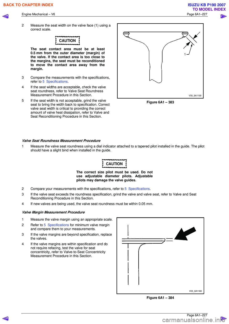
2 Measure the seat width on the valve face (1) using a
correct scale.
CAUTION
The seat contact area must be at least
0.5 mm from the outer diameter (margin) of
the valve. If the contact area is too close to
the margins, the seat must be reconditioned
to move the contact area away from the
margin.
3 Compare the measurements with the specifications,
refer to 5 Specifications .
4 If the seat widths are a cceptable, check the valve
seat roundness, refer to Valve Seat Roundness
Measurement Procedure in this Section.
5 If the seat width is not acceptable, grind the valve
seat to bring the width back to specification. Correct
valve seat width is critical to providing the correct
amount of valve heat dissipat ion, refer to Valve and
Seat Reconditioning Procedure in this Section.
Figure 6A1 – 383
Valve Seat Roundness Measurement Procedure
1 Measure the valve seat roundness using a dial indicator a ttached to a tapered pilot installed in the guide. The pilot
should have a slight bind w hen installed in the guide.
CAUTION
The correct size pilot must be used. Do not
use adjustable diameter pilots. Adjustable
pilots may damage the valve guides.
2 Compare your measurements with the specifications, refer to 5 Specifications.
3 If the valve seat exceeds the roundne ss specification, grind the valve and valve seat, refer to Valve and Seat
Reconditioning Procedure in this Section.
4 If new valves are being used, the valv e seat roundness must be within 0.05 mm.
Valve Margin Measurement Procedure
1 Measure the valve margin using an appropriate scale.
2 Refer to 5 Specifications for minimum valve margin
and compare them to your measurements.
3 If the valve margins are beyond specification, replace the valves.
4 If the valve margins are within specification and do not require refacing, test the valve for seat
concentricity, refer to Valve-to-Seat Concentricity
Measurement Procedure in this Section.
Figure 6A1 – 384
BACK TO CHAPTER INDEX
TO MODEL INDEX
ISUZU KB P190 2007