2007 ISUZU KB P190 check engine
[x] Cancel search: check enginePage 3005 of 6020
Engine Mechanical – V6 Page 6A1–228
Page 6A1–228
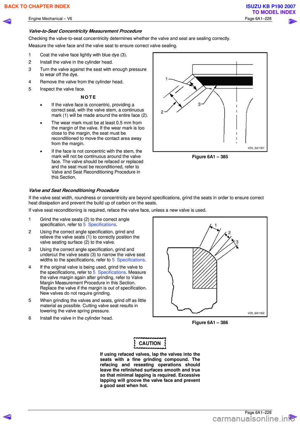
Valve-to-Seat Concentricity Measurement Procedure
Checking the valve-to-seat concentricity determines whether the valve and seat are sealing correctly.
Measure the valve face and the valve s eat to ensure correct valve sealing.
1 Coat the valve face lightly with blue dye (3).
2 Install the valve in the cylinder head.
3 Turn the valve against the seat with enough pressure to wear off the dye.
4 Remove the valve from the cylinder head.
5 Inspect the valve face.
NOTE
• If the valve face is concentric, providing a
correct seal, with the valve stem, a continuous
mark (1) will be made around the entire face (2).
• The wear mark must be at least 0.5 mm from
the margin of the valve. If the wear mark is too
close to the margin, the seat must be
reconditioned to move the contact area away
from the margin.
• If the face is not concentric with the stem, the
mark will not be continuous around the valve
face. The valve should be refaced or replaced
and the seat must be reconditioned, refer to
Valve and Seat Reconditioning Procedure in
this Section.
Figure 6A1 – 385
Valve and Seat Reconditioning Procedure
If the valve seat width, roundness or conc entricity are beyond specifications, grind the seats in order to ensure correct
heat dissipation and prevent the bu ild up of carbon on the seats.
If valve seat reconditioning is required, reface the valve face, unless a new valve is used.
1 Grind the valve seats (2) to the correct angle specification, refer to 5 Specifications.
2 Using the correct angle specification, grind and
relieve the valve seats (1) to correctly position the
valve seating surface (2) to the valve.
3 Using the correct angle specification, grind and
undercut the valve seats (3) to narrow the valve seat
widths to the specifications, refer to 5 Specifications.
4 If the original valve is being used, grind the valve to the specifications, refer to 5 Specifications. Measure
the valve margin again after grinding, refer to Valve
Margin Measurement Procedure in this Section.
Replace the valve if the margin is out of specification.
New valves do not require grinding.
5 When grinding the valves and seats, grind off as little material as possible. Cutti ng valve seat results in
lowering the valve spring pressure.
6 Install the valve in the cylinder head.
Figure 6A1 – 386
CAUTION
If using refaced valves, lap the valves into the
seats with a fine grinding compound. The
refacing and reseati ng operations should
leave the refinished surfaces smooth and true
so that minimal lapping is required. Excessive
lapping will groove the valve face and prevent
a good seat when hot.
BACK TO CHAPTER INDEX
TO MODEL INDEX
ISUZU KB P190 2007
Page 3015 of 6020
Engine Mechanical – V6 Page 6A1–238
Page 6A1–238
4 Replace the engine mount if any of the following conditions are found:
• The hard rubber surface is cove red with heat check cracks,
• The rubber is split through the centre of the engine mount, or
• The rubber is separated from the me tal plate portion of the engine mount.
5 Remove the engine lift brackets, Tool No. EN-46114 from the engine.
Reinstall
The reinstallation procedure for the engi ne mounts is the reverse of the removal procedure, noting the following:
Ensure all fasteners are tightened to the correct torque specification.
Engine mount bracket to
cylinder block attaching bolt
torque specification
................................................................ 43.0 – 57.0 Nm
Engine mount to bracket attaching nut
torque specification
................................................................ 70.0 – 90.0 Nm
Engine mount to frame attaching nut
torque specification
................................................................ 44.0 – 60.0 Nm
BACK TO CHAPTER INDEX
TO MODEL INDEX
ISUZU KB P190 2007
Page 3030 of 6020
Engine Mechanical – V6 Page 6A1–253
Page 6A1–253
k Timing chains, tensioners, shoes, guides & sprockets, refer to 3.16 Timing Chains, Tensioners, Shoes and
Guides .
l Cylinder head assemblies, refer to 3.22 Cylinder Head Assembly.
m Oil pan assembly, refer to 4.2 Oil Pan and Oil Pump Suction Pipe Assembly .
n Piston and connecting rod assemblies, refer to 4.5 Pistons, Pins, Rings, Connecting Rods and Big-end
Bearings .
o Crankshaft assembly, refer to 4.6 Crankshaft and Main Bearings.
p Piston oil nozzles, refer 4.5 Pistons, Pins, Rings, Connecting Rods and Big-end Bearings .
Reassemble
Reassembly of the engine assembly is the reverse of the disassembly procedure.
Reinstall
Reinstallation of the engine assembly is the revers e to the removal procedure, noting the following:
NOTE
Refer to 6 Torque Wrench Specifications for the
correct torque specifications.
1 Tighten the fasteners to the co rrect torque specification.
Engine ground connector bolt
torque specificat ion ............................................ 10.0 Nm
Power steering high pressure line
attaching bolt torque specification ............. 8.0 – 12.0 Nm
Power steering high pressure line
flare nut torque specif ication ................... 25. 0 – 35.0 Nm
Engine mount to frame attaching bolt
torque specification ................................. 44. 0 – 60.0 Nm
Knock Sensor Attaching Nut
torque specification ............................................ 23.0 Nm
2 Use only the specified engine lubricant type and quantity. It is recommended that a fluorescent oil dye, such as that
contained in J 28481-B, be added to assist in any future oil leak diagnosis.
3 Fill the cooling system with the corre ct quantity and grade of coolant, refer to Section 6B1 Engine Cooling – V6.
4 Check transmission fluid level, replenishing as required, using the specified lubricant for the transmission fitted,
refer to Section 7C1 Automatic – 4L60E – General Information .
5 Disable the ignition system, refer to Section 6C1-3 Engine Management – V6 – Service Operations.
6 Crank the engine several times. Listen for any unusual noises or evidence that parts are binding.
7 Enable the ignition system. Start t he engine and listen for any unusual noises.
8 Check the vehicle oil pressure gauge or warning indica tor and confirm the engine has acceptable oil pressure. If
required, install an oil pressure gauge and m easure the engine oil pressure, refer to 2.19 Engine Oil Pressure
Diagnosis .
9 Run the engine at about 1,000 r. p.m. until the engine has reached normal operating temperature.
10 Listen for any unusual noises.
11 Check for oil, fuel, coolant and exhaust leaks wh ile the engine is running, correcting as required.
12 Perform a final inspection for correct engine oil and coolant levels.
BACK TO CHAPTER INDEX
TO MODEL INDEX
ISUZU KB P190 2007
Page 3042 of 6020
Engine Mechanical – V6 Page 6A1–265
Page 6A1–265
4.5 Pistons, Pins, Rings, Connecting Rods
and Big-end Bearings
Remove
1 Remove the engine assembly, refer to 4.1 Engine .
2 Remove both cylinder head assemblies, refer to 3.22 Cylinder Head Assembly.
3 Remove the oil pan assembly, refer to 4.2 Oil Pan and Oil Pump Suction Pipe Assembly .
4 Mark the top of the piston being remo ved to identify its specific bore.
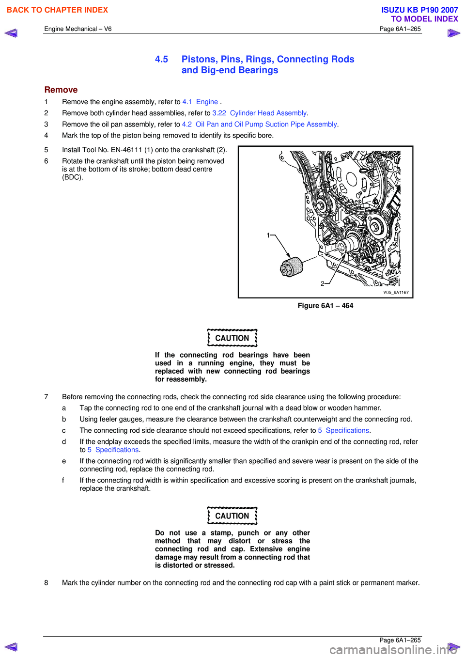
5 Install Tool No. EN-46111 (1) onto the crankshaft (2).
6 Rotate the crankshaft until the piston being removed is at the bottom of its stroke; bottom dead centre
(BDC).
Figure 6A1 – 464
CAUTION
If the connecting rod bearings have been
used in a running engine, they must be
replaced with new connecting rod bearings
for reassembly.
7 Before removing the connecting rods, check the connec ting rod side clearance using the following procedure:
a Tap the connecting rod to one end of the cranks haft journal with a dead blow or wooden hammer.
b Using feeler gauges, measure the clearance between the crankshaft counterweight and the connecting rod.
c The connecting rod side clearance should not exceed specifications, refer to 5 Specifications.
d If the endplay exceeds the specified limits, measure the width of the crankpin end of the connecting rod, refer
to 5 Specifications .
e If the connecting rod width is significantly smaller than specified and severe wear is present on the side of the
connecting rod, replac e the connecting rod.
f If the connecting rod width is within specification and excessive scoring is present on the crankshaft journals,
replace the crankshaft.
CAUTION
Do not use a stamp, punch or any other
method that may distort or stress the
connecting rod and cap. Extensive engine
damage may result from a connecting rod that
is distorted or stressed.
8 Mark the cylinder number on the connec ting rod and the connecting rod cap with a paint stick or permanent marker.
BACK TO CHAPTER INDEX
TO MODEL INDEX
ISUZU KB P190 2007
Page 3047 of 6020
Engine Mechanical – V6 Page 6A1–270
Page 6A1–270
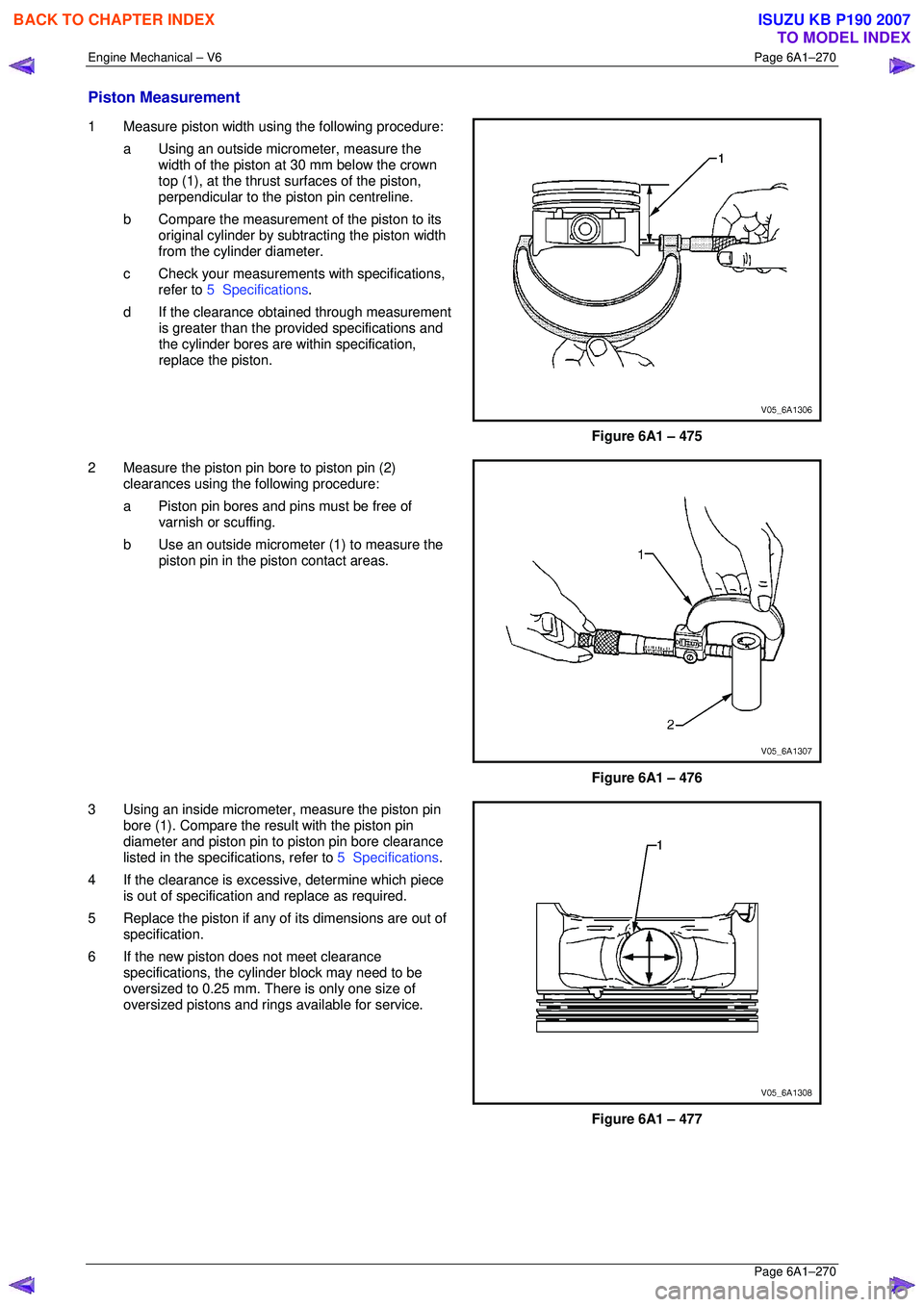
Piston Measurement
1 Measure piston width using the following procedure:
a Using an outside micr ometer, measure the
width of the piston at 30 mm below the crown
top (1), at the thrust surfaces of the piston,
perpendicular to the piston pin centreline.
b Compare the measurement of the piston to its
original cylinder by subtracting the piston width
from the cylinder diameter.
c Check your measurements with specifications, refer to 5 Specifications .
d If the clearance obtai ned through measurement
is greater than the prov ided specifications and
the cylinder bores are wi thin specification,
replace the piston.
Figure 6A1 – 475
2 Measure the piston pin bore to piston pin (2) clearances using the following procedure:
a Piston pin bores and pins must be free of varnish or scuffing.
b Use an outside micrometer (1) to measure the
piston pin in the piston contact areas.
Figure 6A1 – 476
3 Using an inside micrometer , measure the piston pin
bore (1). Compare the resu lt with the piston pin
diameter and piston pin to piston pin bore clearance
listed in the specifications, refer to 5 Specifications.
4 If the clearance is excessive, determine which piece is out of specification and replace as required.
5 Replace the piston if any of its dimensions are out of
specification.
6 If the new piston does not meet clearance specifications, the cylinder block may need to be
oversized to 0.25 mm. There is only one size of
oversized pistons and rings available for service.
Figure 6A1 – 477
BACK TO CHAPTER INDEX
TO MODEL INDEX
ISUZU KB P190 2007
Page 3048 of 6020
Engine Mechanical – V6 Page 6A1–271
Page 6A1–271
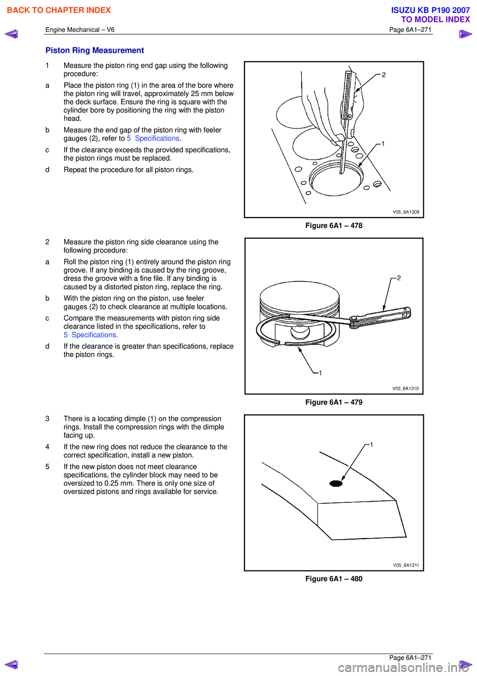
Piston Ring Measurement
1 Measure the piston ring end gap using the following
procedure:
a Place the piston ring (1) in the area of the bore where
the piston ring will travel, approximately 25 mm below
the deck surface. Ensure t he ring is square with the
cylinder bore by positioning the ring with the piston
head.
b Measure the end gap of the piston ring with feeler
gauges (2), refer to 5 Specifications.
c If the clearance exceeds t he provided specifications,
the piston rings must be replaced.
d Repeat the procedure for all piston rings.
Figure 6A1 – 478
2 Measure the piston ring side clearance using the
following procedure:
a Roll the piston ring (1) ent irely around the piston ring
groove. If any binding is c aused by the ring groove,
dress the groove with a fine file. If any binding is
caused by a distorted piston ring, replace the ring.
b With the piston ring on the piston, use feeler
gauges (2) to check clearance at multiple locations.
c Compare the measurement s with piston ring side
clearance listed in the spec ifications, refer to
5 Specifications .
d If the clearance is greater than specifications, replace
the piston rings.
Figure 6A1 – 479
3 There is a locating dimple (1) on the compression rings. Install the compression rings with the dimple
facing up.
4 If the new ring does not r educe the clearance to the
correct specification, install a new piston.
5 If the new piston does not meet clearance specifications, the cylinder block may need to be
oversized to 0.25 mm. There is only one size of
oversized pistons and rings available for service.
Figure 6A1 – 480
BACK TO CHAPTER INDEX
TO MODEL INDEX
ISUZU KB P190 2007
Page 3055 of 6020
Engine Mechanical – V6 Page 6A1–278
Page 6A1–278
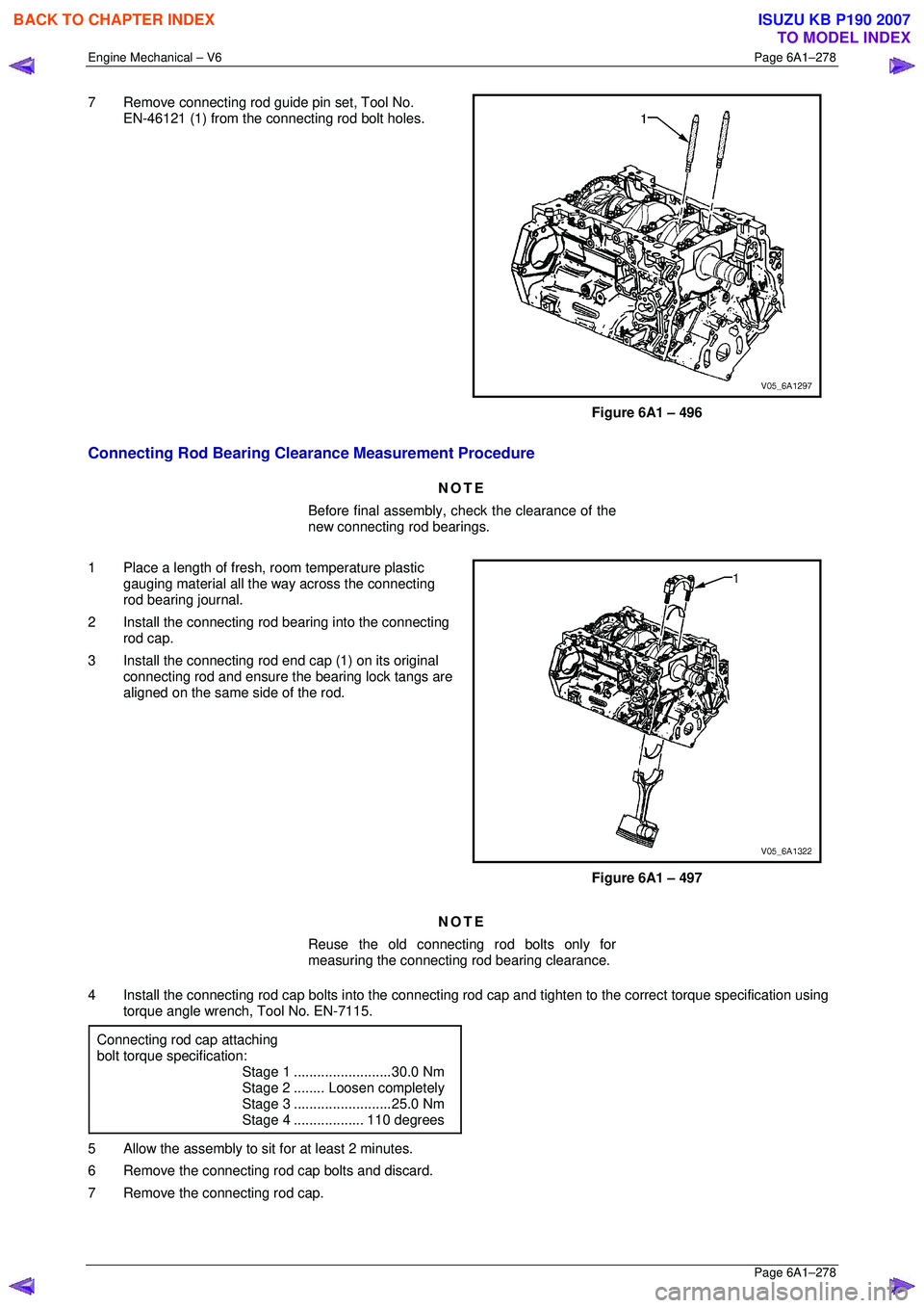
7 Remove connecting rod guide pin set, Tool No.
EN-46121 (1) from the connecting rod bolt holes.
Figure 6A1 – 496
Connecting Rod Bearing Clearance Measurement Procedure
NOTE
Before final assembly, check the clearance of the
new connecting rod bearings.
1 Place a length of fresh, room temperature plastic
gauging material all the way across the connecting
rod bearing journal.
2 Install the connecting rod bearing into the connecting
rod cap.
3 Install the connecting rod end cap (1) on its original
connecting rod and ensure t he bearing lock tangs are
aligned on the same side of the rod.
Figure 6A1 – 497
NOTE
Reuse the old connecting rod bolts only for
measuring the connecting rod bearing clearance.
4 Install the connecting rod cap bolts in to the connecting rod cap and tighten to the correct torque specification using
torque angle wrench, Tool No. EN-7115.
Connecting rod cap attaching
bolt torque specification:
Stage 1 .........................30.0 Nm
Stage 2 ........Loosen completely
Stage 3 .........................25.0 Nm
Stage 4 ..................110 degrees
5 Allow the assembly to sit for at least 2 minutes.
6 Remove the connecting rod cap bolts and discard.
7 Remove the connecting rod cap.
BACK TO CHAPTER INDEX
TO MODEL INDEX
ISUZU KB P190 2007
Page 3132 of 6020
Engine Mechanical – V6 Page 6A1–355
Page 6A1–355
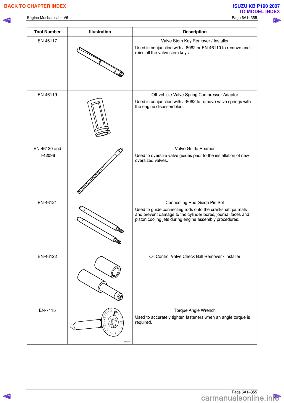
Tool Number Illustration Description
EN-46117
Valve Stem Key Remover / Installer
Used in conjunction with J-8062 or EN-46110 to remove and
reinstall the valve stem keys.
EN-46119
Off-vehicle Valve Spring Compressor Adaptor
Used in conjunction with J-8062 to remove valve springs with
the engine disassembled.
EN-46120 and
J-42096
Valve Guide Reamer
Used to oversize valve guides prior to the installation of new
oversized valves.
EN-46121
Connecting Rod Guide Pin Set
Used to guide connecting rods onto the crankshaft journals
and prevent damage to the cylinder bores, journal faces and
piston cooling jets during engine assembly procedures.
EN-46122
Oil Control Valve Check Ball Remover / Installer
EN-7115
Torque Angle Wrench
Used to accurately tighten fasteners when an angle torque is
required.
BACK TO CHAPTER INDEX
TO MODEL INDEX
ISUZU KB P190 2007