2007 ISUZU KB P190 coolant temperature
[x] Cancel search: coolant temperaturePage 1365 of 6020
ENGINE MECHANICAL (4JK1/4JJ1) 6A-5
EGR system
Based upon data, including water temperature, engine
speeds or engine loads, it is controlled via Engine
Control Module (ECM) to purify exhaust by recycling
part of it.
Its main components include an EGR valve, an EGR
cooler and various sensors.
Connecting rod cap bolt
The angular tightening method of the connecting rod
cap bolt further increases reliability and durability.
Fuel rail-type electronic control injection system
The fuel rail-type electronic control injection system is
composed of a fuel supply pump that sets the target
pressure of high-pressure fuel and supply it, a fuel rail
that measures such high-pressure fuel and a fuel
injector that turns it into a fine spray and injects it. Each
is controlled via ECM based upon various signals, while
injection timing or fuel injection quantity is controlled
under every possible driving condition.
Fuel injector
The fuel injector is a 6-hole nozzle that adjusts fuel
injection quantity or injection timing by opening o
r
closing an electromagnetic valve on the head of the fuel
injector.
ECM corrects the dispersion of fuel injection quantit
y
between fuel injector according to ID code data in
memory. At the replacement of fuel injector, ID code
data should be stored in ECM.
Fuel filter with sedimenter
It is a fuel filter with sedimenter that gets rid of water by
making use of the difference in specific gravity between
light oil and water, which comes with an indicator that
notifies you that it is filled with water.
Preheating system
The preheating system consists of the ECM, the glow
relay, glow plugs and the glow indicator lamp. The
preheating system is operated when the engine coolant
temperature is low, and makes the engine easy to start.
Lubrication system
It is an oil filter with full-flow bypass, which uses a
water-cool oil cooler and oil jet to cool the piston.
Functional inspection
Inspection/adjustment of valve clearance 1. Inspection of valve clearance
• Remove the fuel injector harness assembly.
• Remove the leak off hose.
• Remove the cylinder head cover.
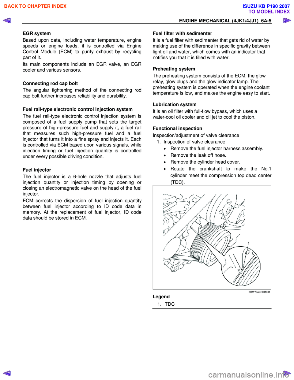
• Rotate the crankshaft to make the No.1
cylinder meet the compression top dead cente
r
(TDC).
RTW 76ASH001301
Legend
1. TDC
BACK TO CHAPTER INDEX
TO MODEL INDEX
ISUZU KB P190 2007
Page 1373 of 6020
ENGINE MECHANICAL (4JK1/4JJ1) 6A-13
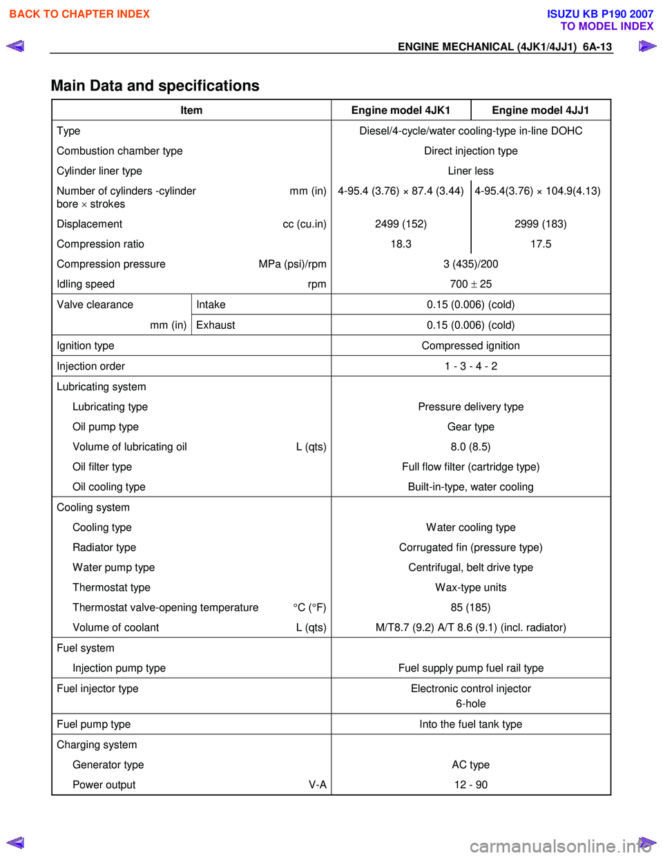
Main Data and specifications
Item Engine model 4JK1 Engine model 4JJ1
Type Diesel/4-cycle/water cooling-type in-line DOHC
Combustion chamber type Direct injection type
Cylinder liner type Liner less
Number of cylinders -cylinder
bore × strokes mm (in) 4-95.4 (3.76) × 87.4 (3.44) 4-95.4(3.76) × 104.9(4.13)
Displacement
cc (cu.in) 2499 (152) 2999 (183)
Compression ratio 18.3 17.5
Compression pressure MPa (psi)/rpm 3 (435)/200
Idling speed rpm 700 ± 25
Valve clearance Intake 0.15 (0.006) (cold)
mm (in) Exhaust 0.15 (0.006) (cold)
Ignition type Compressed ignition
Injection order 1 - 3 - 4 - 2
Lubricating system
Lubricating type Pressure delivery type
Oil pump type Gear type
Volume of lubricating oil L (qts) 8.0 (8.5)
Oil filter type Full flow filter (cartridge type)
Oil cooling type Built-in-type, water cooling
Cooling system
Cooling type W ater cooling type
Radiator type Corrugated fin (pressure type)
W ater pump type Centrifugal, belt drive type
Thermostat type W ax-type units
Thermostat valve-opening temperature °C ( °F) 85 (185)
Volume of coolant L (qts) M/T8.7 (9.2) A/T 8.6 (9.1) (incl. radiator)
Fuel system
Injection pump type Fuel supply pump fuel rail type
Fuel injector type Electronic control injector
6-hole
Fuel pump type Into the fuel tank type
Charging system
Generator type AC type
Power output V-A 12 - 90
BACK TO CHAPTER INDEX
TO MODEL INDEX
ISUZU KB P190 2007
Page 1525 of 6020
6B-2 ENGINE COOLING (4JK1/4JJ1)
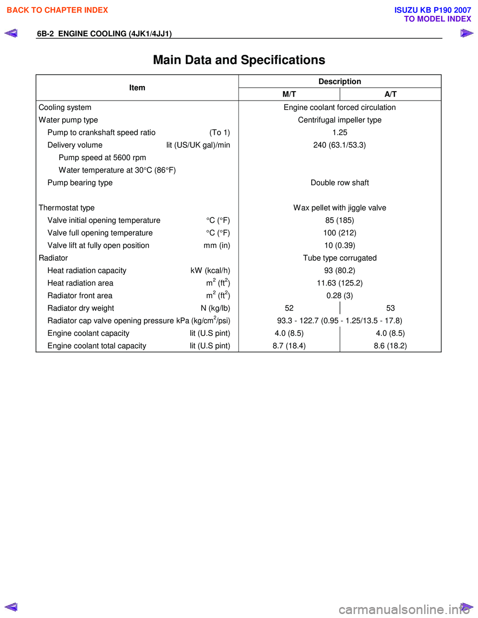
Main Data and Specifications
Description Item
M/T A/T
Cooling system
W ater pump type
Pump to crankshaft speed ratio (To 1)
Delivery volume lit (US/UK gal)/min
Pump speed at 5600 rpm
W ater temperature at 30 °C (86 °F)
Pump bearing type
Thermostat type
Valve initial opening temperature °C ( °F)
Valve full opening temperature °C ( °F)
Valve lift at fully open position mm (in) Engine coolant forced circulation
Centrifugal impeller type 1.25
240 (63.1/53.3)
Double row shaft
W ax pellet with jiggle valve 85 (185)
100 (212) 10 (0.39)
Radiator Tube type corrugated
Heat radiation capacity kW (kcal/h) 93 (80.2)
Heat radiation area m2 (ft2) 11.63 (125.2)
Radiator front area m2 (ft2) 0.28 (3)
Radiator dry weight N (kg/lb) 52 53
Radiator cap valve opening pressure kPa (kg/cm2/psi) 93.3 - 122.7 (0.95 - 1.25/13.5 - 17.8)
Engine coolant capacity lit (U.S pint) 4.0 (8.5) 4.0 (8.5)
Engine coolant total capacity lit (U.S pint) 8.7 (18.4) 8.6 (18.2)
BACK TO CHAPTER INDEX
TO MODEL INDEX
ISUZU KB P190 2007
Page 1526 of 6020
ENGINE COOLING (4JK1/4JJ1) 6B-3
General Description
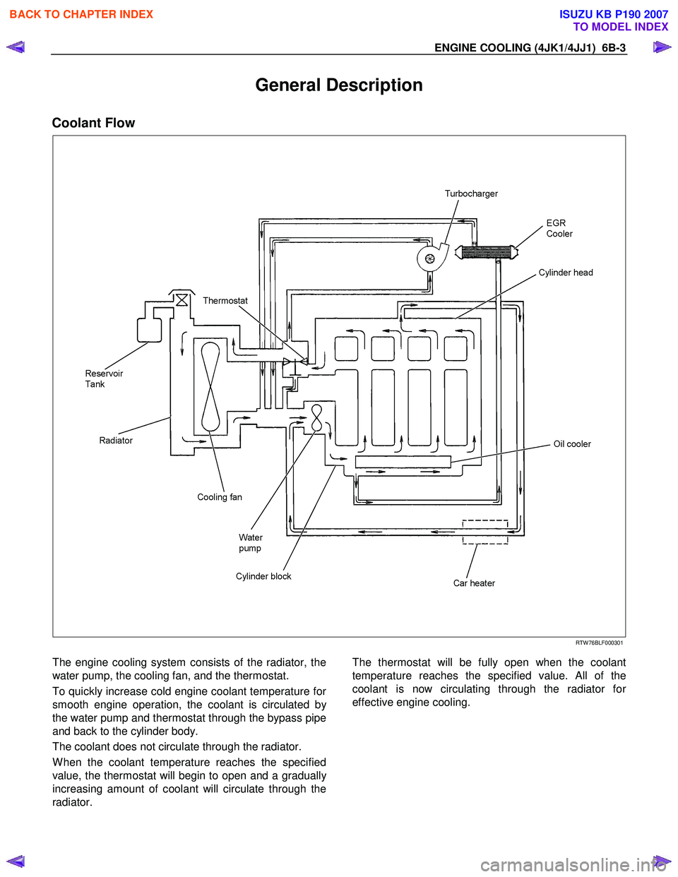
Coolant Flow
RTW 76BLF000301
The engine cooling system consists of the radiator, the
water pump, the cooling fan, and the thermostat.
To quickly increase cold engine coolant temperature fo
r
smooth engine operation, the coolant is circulated by
the water pump and thermostat through the bypass pipe
and back to the cylinder body.
The coolant does not circulate through the radiator.
W hen the coolant temperature reaches the specified
value, the thermostat will begin to open and a graduall
y
increasing amount of coolant will circulate through the
radiator.
The thermostat will be fully open when the coolant
temperature reaches the specified value. All of the
coolant is now circulating through the radiator fo
r
effective engine cooling.
BACK TO CHAPTER INDEX
TO MODEL INDEX
ISUZU KB P190 2007
Page 1529 of 6020
6B-6 ENGINE COOLING (4JK1/4JJ1)
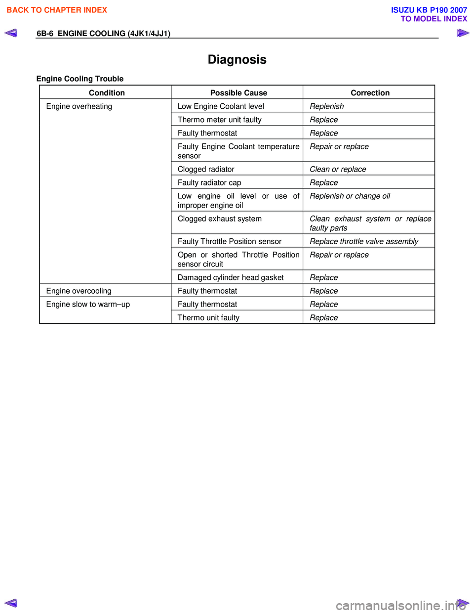
Diagnosis
Engine Cooling Trouble
Condition Possible Cause Correction
Low Engine Coolant level Replenish
Thermo meter unit faulty Replace
Faulty thermostat Replace
Faulty Engine Coolant temperature
sensor Repair or replace
Clogged radiator
Clean or replace
Faulty radiator cap Replace
Low engine oil level or use of
improper engine oil Replenish or change oil
Clogged exhaust system
Clean exhaust system or replace
faulty parts
Faulty Throttle Position sensor Replace throttle valve assembly
Open or shorted Throttle Position
sensor circuit Repair or replace
Engine overheating
Damaged cylinder head gasket Replace
Engine overcooling Faulty thermostat Replace
Faulty thermostat Replace Engine slow to warm–up
Thermo unit faulty Replace
BACK TO CHAPTER INDEX
TO MODEL INDEX
ISUZU KB P190 2007
Page 1530 of 6020
ENGINE COOLING (4JK1/4JJ1) 6B-7
Draining and Refilling Cooling System
Before draining the cooling system, inspect the system
and perform any necessary service to ensure that it is
clean, does not leak and is in proper working order.
The engine coolant (EC) level should be between the
“MIN" and “MAX" lines of the reserve tank when the
engine is cold. If low, check for leakage and add EC up
to the “MAX" line.
There should not be any excessive deposit of rust o
r
scales around the radiator cap or radiator filler hole, and
the EC should also be free from oil.
Replace the EC if excessively dirty.
1. Remove the radiator skid plate.
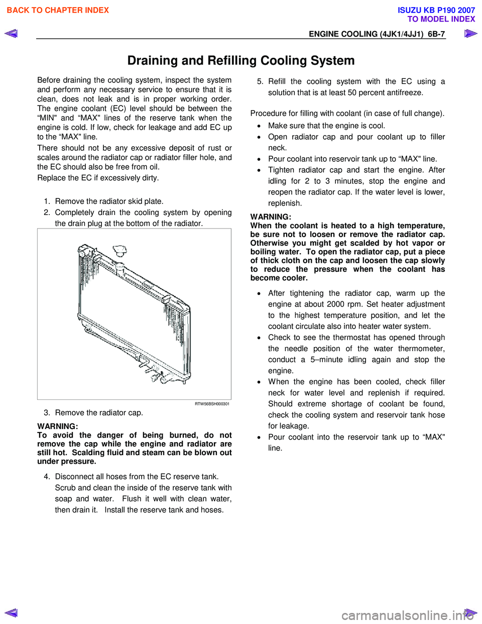
2. Completely drain the cooling system by opening the drain plug at the bottom of the radiator.
RTW 56BSH000301
3. Remove the radiator cap.
WARNING:
To avoid the danger of being burned, do not
remove the cap while the engine and radiator are
still hot. Scalding fluid and steam can be blown out
under pressure.
4. Disconnect all hoses from the EC reserve tank.
Scrub and clean the inside of the reserve tank with soap and water. Flush it well with clean water,
then drain it. Install the reserve tank and hoses.
5. Refill the cooling system with the EC using a
solution that is at least 50 percent antifreeze.
Procedure for filling with coolant (in case of full change).
• Make sure that the engine is cool.
• Open radiator cap and pour coolant up to fille
r
neck.
• Pour coolant into reservoir tank up to “MAX" line.
• Tighten radiator cap and start the engine. Afte
r
idling for 2 to 3 minutes, stop the engine and
reopen the radiator cap. If the water level is lower,
replenish.
WARNING:
When the coolant is heated to a high temperature,
be sure not to loosen or remove the radiator cap.
Otherwise you might get scalded by hot vapor o
r
boiling water. To open the radiator cap, put a piece
of thick cloth on the cap and loosen the cap slowly
to reduce the pressure when the coolant has
become cooler.
• After tightening the radiator cap, warm up the
engine at about 2000 rpm. Set heater adjustment
to the highest temperature position, and let the
coolant circulate also into heater water system.
• Check to see the thermostat has opened through
the needle position of the water thermometer,
conduct a 5–minute idling again and stop the
engine.
• W hen the engine has been cooled, check fille
r
neck for water level and replenish if required.
Should extreme shortage of coolant be found,
check the cooling system and reservoir tank hose
for leakage.
• Pour coolant into the reservoir tank up to “MAX"
line.
BACK TO CHAPTER INDEX
TO MODEL INDEX
ISUZU KB P190 2007
Page 1534 of 6020
ENGINE COOLING (4JK1/4JJ1) 6B-11
Thermostat
Read this Section carefully before performing any
removal and installation procedure. This Section gives
you important points as well as the order of operation.
Be sure that you understand everything in this Section
before you begin.
Removal
1. Remove the engine cover.
2. Radiator Upper Hose a. Partially drain the engine coolant.
b. Remove the radiator upper hose.
c. Remove the engine harness clip.
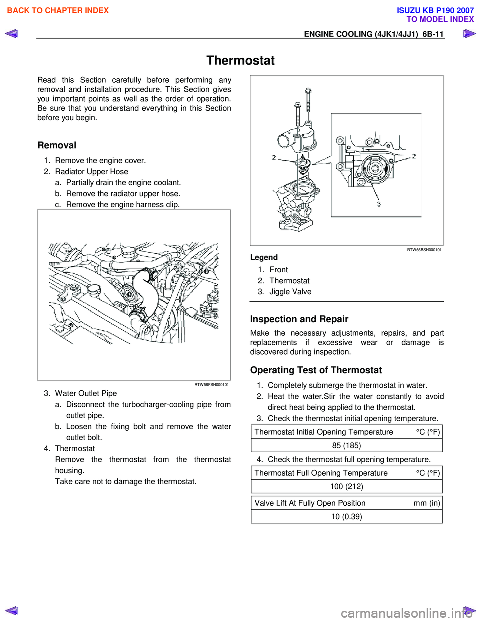
RTW 56FSH000101
3. W ater Outlet Pipe
a. Disconnect the turbocharger-cooling pipe from outlet pipe.
b. Loosen the fixing bolt and remove the wate
r
outlet bolt.
4. Thermostat
Remove the thermostat from the thermostat housing.
Take care not to damage the thermostat.
RTW 56BSH000101
Legend
1. Front
2. Thermostat
3. Jiggle Valve
Inspection and Repair
Make the necessary adjustments, repairs, and part
replacements if excessive wear or damage is
discovered during inspection.
Operating Test of Thermostat
1. Completely submerge the thermostat in water.
2. Heat the water.Stir the water constantly to avoid direct heat being applied to the thermostat.
3. Check the thermostat initial opening temperature.
Thermostat Initial Opening Temperature °C (°F)
85 (185)
4. Check the thermostat full opening temperature.
Thermostat Full Opening Temperature °C (°F)
100 (212)
Valve Lift At Fully Open Position mm (in)
10 (0.39)
BACK TO CHAPTER INDEX
TO MODEL INDEX
ISUZU KB P190 2007
Page 1578 of 6020

FUEL SYSTEM (4JK1/4JJ1) 6C-37
24. Install the A/C compressor.
RTW 56ASH004201
Legend
1. A/C Compressor Bracket
2. Intake Duct
3. A/C Compressor
Tighten the bolts to the specified torque.
Tightening torque: 44 N ⋅
⋅⋅
⋅
m (4.5 kg ⋅
⋅⋅
⋅
m / 33 lb ft)
25. Install the battery.
26. Install the A/C compressor adjust pulley.
RTW 56ASH010601
Legend
1. Bolt
2. Nut
Tighten the nut and bolt to the specified torque.
Bolt Tightening torque: 25 N ⋅
⋅⋅
⋅
m (2.5 kg ⋅
⋅⋅
⋅
m/18 lb ft)
Nut Tightening torque: 25 N ⋅
⋅⋅
⋅
m (2.5 kg ⋅
⋅⋅
⋅
m/18 lb ft)
27. Install the A/C compressor drive belt.
Refer to the drive belt tension check procedure fo
r
Heating and air conditioning in this manual.
28. Install the cooling fan.
29. Install the fan guide.
30. Install the radiator upper hose.
31. Replenish the engine coolant.
Fuel Supply Pump Relearn Procedure
The ECM goes through a fuel supply pump learn
procedure to fine tune the current supplied to the fuel
rail pressure (FRP) regulator. This learning process in
only performed when the engine is idling.
1. Install the scan tool.
2. Turn ON the ignition, with the engine OFF.
3. Command the Supply Pump Learn Reset with the scan tool.
4. Observe the Supply Pump Status parameter with the scan tool. Confirm the scan tool indicates Not
Learn.
5. Start the engine and let idle until engine coolant temperature (ECT) reads 149°F (65°C) or highe
r
while observing Supply Pump Status parameter
with the scant tool. The scan tool changes status
Not Learn > Learning > Learned.
6. If the ECM has correctly learned the fuel supply pump current adjustment, the Supply Pump Status
parameter on the scan tool will repeatedly indicate
Learning and Learned.
BACK TO CHAPTER INDEX
TO MODEL INDEX
ISUZU KB P190 2007