Page 982 of 6020
6C – 18 FUEL SYSTEM
INJECTION PUMP
REMOVAL AND INSTALLATION
Read this Section carefully before performing any removal and installation procedure. This Section gives you
important points as well as the order of operation. Be sure that you understand everything in this Section before you
begin.
Removal
1. Battery
Remove the battery from the battery tray.
Battery
Battery tray
P1010011
2. Drive Belt 1) Loosen the adjust bolt of the power steering pump pulley.
2) Remove the drive belt.
3. Power Steering Pump Assembly
P1010003
4. Accelerator Control Cable
Disconnect the accelerator cable from the intake throttle.
5. Vacuum Hose
Disconnect the vacuum hose from the EGR valve and the intake throttle.
6. Fan
BACK TO CHAPTER INDEX
TO MODEL INDEX
ISUZU KB P190 2007
Page 988 of 6020
6C – 24 FUEL SYSTEM
13. Throttle Position Sensor Harness Connector
(4JA1TC/4JH1TC only)
Reconnect the harness connector to the throttle position
sensor.
14. Power Steering Pump Bracket
15. Fan
16. Vacuum Hose
Connect the vacuum hose to the EGR valve and the
intake throttle.
Euro under Euro I Euro II Euro III
4JA1L without with with Not used
4JA1TC Not used Not used Not used With cooler
(EGR cooler)
4JH1TC without with with With
(EGR cooler)
17. Accelerator Control Cable
1) Connect the accelerator cable to the injection pump (4JA1T) the intake throttle. (4JA1TC/4JH1TC only)
18. Power Steering Pump Assembly
19. Drive Belt
Install the drive belt and adjust the belt tension.
20. Battery
BACK TO CHAPTER INDEX
TO MODEL INDEX
ISUZU KB P190 2007
Page 1008 of 6020

ENGINE ELECTRICAL 6D – 7
GENERATOR
REMOVAL AND INSTALLATION
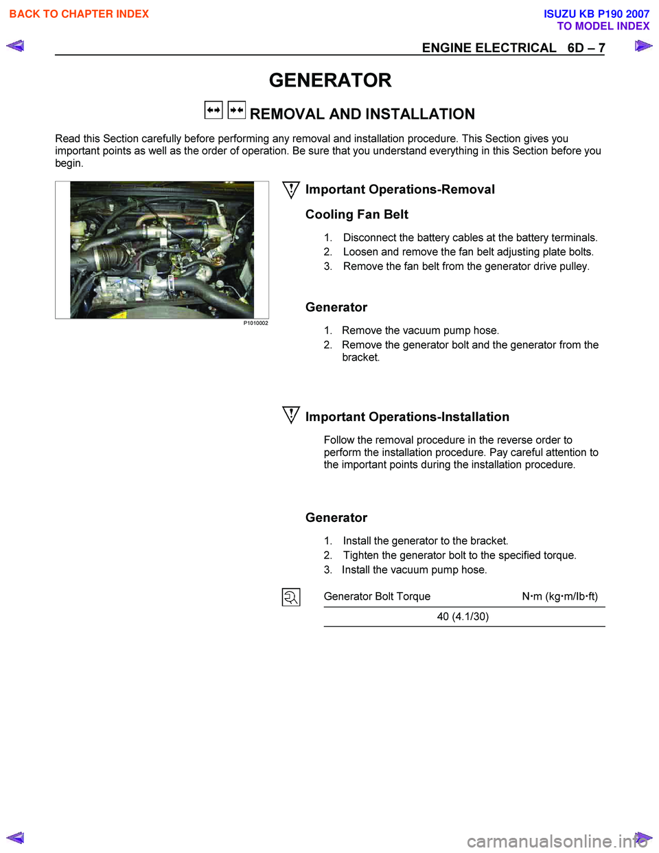
Read this Section carefully before performing any removal and installation procedure. This Section gives you
important points as well as the order of operation. Be sure that you understand everything in this Section before you
begin.
P1010002
Important Operations-Removal
Cooling Fan Belt
1. Disconnect the battery cables at the battery terminals.
2. Loosen and remove the fan belt adjusting plate bolts.
3. Remove the fan belt from the generator drive pulley.
Generator
1. Remove the vacuum pump hose.
2. Remove the generator bolt and the generator from the bracket.
Important Operations-Installation
Follow the removal procedure in the reverse order to
perform the installation procedure. Pay careful attention to
the important points during the installation procedure.
Generator
1. Install the generator to the bracket.
2. Tighten the generator bolt to the specified torque.
3. Install the vacuum pump hose.
Generator Bolt Torque N �m (kg �m/Ib �ft)
40 (4.1/30)
BACK TO CHAPTER INDEX
TO MODEL INDEX
ISUZU KB P190 2007
Page 1009 of 6020
6D – 8 ENGINE ELECTRICAL
033RY00009
Cooling Fan Drive Belt
1. Hold the generator toward the engine.
2. Install the fan belt to the three pulleys. 1 Crankshaft pulley
2 Generator pulley
3 Cooling fan drive pulley
3. Adjust the fan belt tension
Fan belt tension is adjusted by moving the generator.
Depress the drive belt mid-portion with a 98N (10
kg/22 Ib) force.
Cooling Fan Drive Belt Deflection mm (in)
New belt 4 - 7 (0.16 - 0.28)
Reuse belt 6 - 9 (0.24 - 0.35)
4. Tighten the adjusting plate bolts to the specified torque.
Adjusting Plate Bolt N·m (kg·m/lb·ft)
19 (1.9/14)
5. Reconnect the battery cable to the battery.
BACK TO CHAPTER INDEX
TO MODEL INDEX
ISUZU KB P190 2007
Page 1023 of 6020

6D – 22 ENGINE ELECTRICAL
STARTER MOTOR
REMOVAL AND INSTALLATION
Read this Section carefully before performing any removal and installation procedure. This Section gives you
important points as well as the order of operation. Be sure that you understand everything in this Section before you
begin.
Important Operations - Removal
Starter Motor
1. Disconnect the battery cable and the ground cable at the battery terminals.
2. Disconnect the magnetic switch cable at the terminal bolts.
3. Disconnect the battery cable at the starter motor and the ground cable at the cylinder body.
4. Remove the starter motor from the engine.
Important Operations – Installation
Follow the removal procedure in the reverse order to
perform the installation procedure. Pay careful attention to
the important points during the installation procedure.
Starter Motor
1. Install the starter motor to the rear plate.
2. Tighten the starter motor bolts to the specified torque.
Starter Motor Bolt Torque N⋅m (kg ⋅m/lb ⋅ft)
85 (8.7/63)
3. Reconnect the battery cable at the starter motor and
the ground cable at the cylinder body.
4. Reconnect the battery cable and the ground cable at the battery terminals.
BACK TO CHAPTER INDEX
TO MODEL INDEX
ISUZU KB P190 2007
Page 1033 of 6020
6D – 32 ENGINE ELECTRICAL
MAGNETIC SWITCH
The following tests must be performed with the starter
motor fully assembled.
The yoke lead wire must be disconnected from the “M ”
terminal.
To prevent coil burning, complete each test as quickly as
possible (within three to five seconds).
RTW46DSH004601
Temporarily connect the solenoid switch between the
clutch and the housing and run the following test.
Complete each test within three to five seconds.
1. Pull-in Test Connect the battery negative terminal with the solenoid
switch body and the M terminal. When current is applied to
the S terminal from the battery positive terminal, the pinion
should flutter.
RTW46DSH005901
2. Hold-in Maintenance Test
Disconnect the lead at the M terminal. The pinion should
continue to flutter.
RTW46DSH004701
3. Return Test
Disconnect the battery positive lead at the S terminal.
The pinion should return to its home position.
BACK TO CHAPTER INDEX
TO MODEL INDEX
ISUZU KB P190 2007
Page 1052 of 6020
6E-18 Engine Control System (4JH1)
Component Locator
Engine Controls Component Views
3
4
1 2
6
45
Legend
1. Mass Air Flow (MAF) & Intake Air Temperature (IAT) Sensor Assembly
2. Throttle Cable
3. Air Cleaner Case
4. Battery
5. Relay & Fuse Box
6. EGR Cooler (Euro3) / EGR Pipe (Except Euro3)
BACK TO CHAPTER INDEX
TO MODEL INDEX
ISUZU KB P190 2007
Page 1056 of 6020

6E-22 Engine Control System (4JH1)
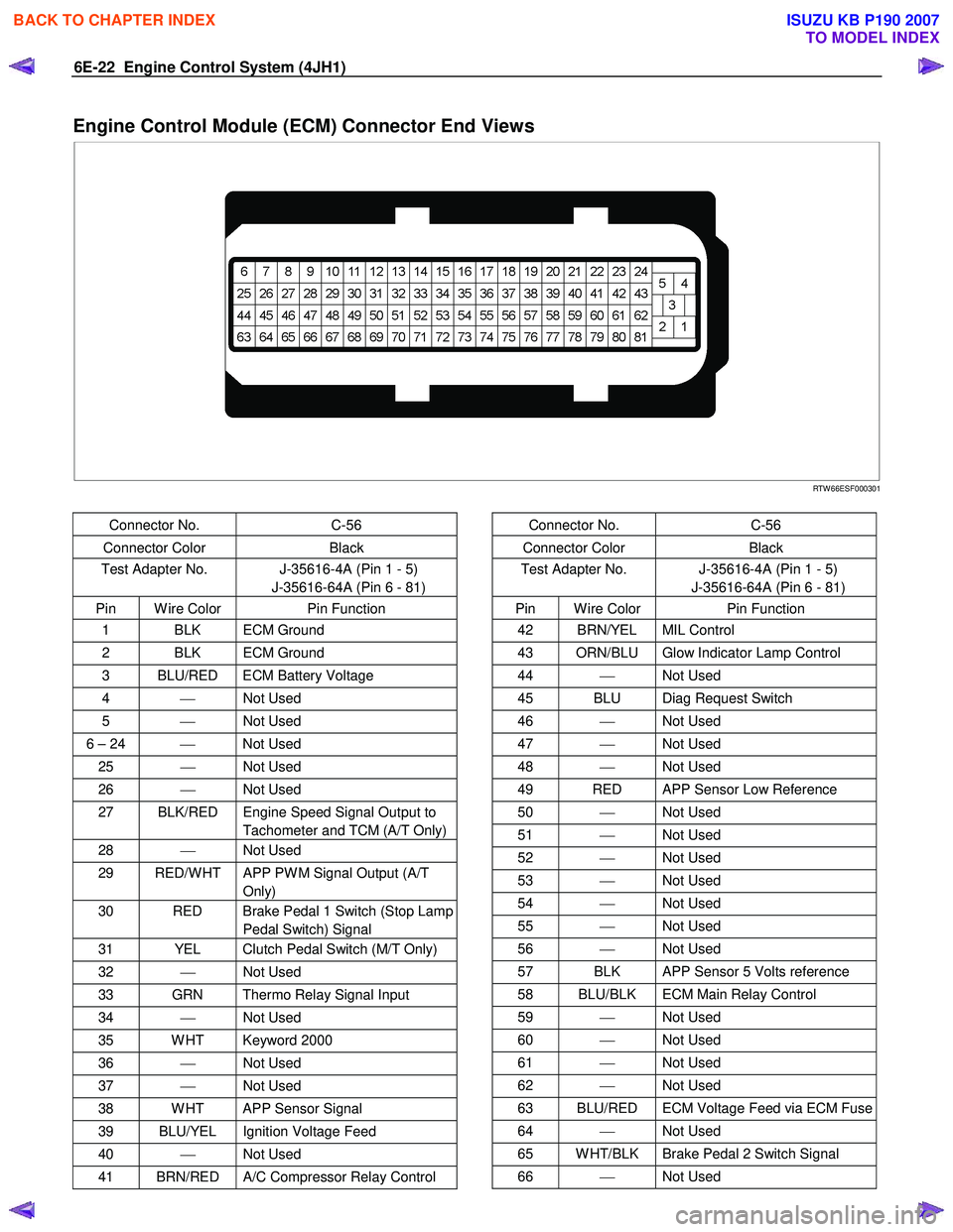
Engine Control Module (ECM) Connector End Views
RTW 66ESF000301
Connector No. C-56
Connector Color Black
Test Adapter No. J-35616-4A (Pin 1 - 5)
J-35616-64A (Pin 6 - 81)
Pin W ire Color Pin Function
1 BLK ECM Ground
2 BLK ECM Ground
3 BLU/RED ECM Battery Voltage
4 Not Used
5 Not Used
6 – 24 Not Used
25 Not Used
26 Not Used
27 BLK/RED Engine Speed Signal Output to
Tachometer and TCM (A/T Only)
28 Not Used
29 RED/W HT APP PW M Signal Output (A/T
Only)
30 RED Brake Pedal 1 Switch (Stop Lamp Pedal Switch) Signal
31 YEL Clutch Pedal Switch (M/T Only)
32 Not Used
33 GRN Thermo Relay Signal Input
34 Not Used
35 W HT Keyword 2000
36 Not Used
37 Not Used
38 W HT APP Sensor Signal
39 BLU/YEL Ignition Voltage Feed
40 Not Used
41 BRN/RED A/C Compressor Relay Control
Connector No. C-56
Connector Color Black
Test Adapter No. J-35616-4A (Pin 1 - 5)
J-35616-64A (Pin 6 - 81)
Pin W ire Color Pin Function
42 BRN/YEL MIL Control
43 ORN/BLU Glow Indicator Lamp Control
44 Not Used
45 BLU Diag Request Switch
46 Not Used
47 Not Used
48 Not Used
49 RED APP Sensor Low Reference
50 Not Used
51 Not Used
52 Not Used
53 Not Used
54 Not Used
55 Not Used
56 Not Used
57 BLK APP Sensor 5 Volts reference
58 BLU/BLK ECM Main Relay Control
59 Not Used
60 Not Used
61 Not Used
62 Not Used
63 BLU/RED ECM Voltage Feed via ECM Fuse
64 Not Used
65 W HT/BLK Brake Pedal 2 Switch Signal
66 Not Used
BACK TO CHAPTER INDEX
TO MODEL INDEX
ISUZU KB P190 2007