2007 ISUZU KB P190 spark plugs
[x] Cancel search: spark plugsPage 3311 of 6020
Engine Management – V6 – Diagnostics Page 6C1-2–33
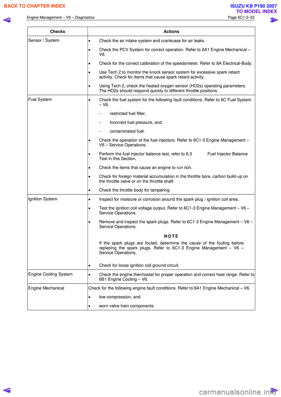
Checks Actions
Sensor / System
• Check the air intake system and crankcase for air leaks.
• Check the PCV System for correct operation. Refer to 6A1 Engine Mechanical –
V6.
• Check for the correct calibration of the speedometer. Refer to 8A Electrical-Body.
• Use Tech 2 to monitor the knock sensor system for excessive spark retard
activity. Check for items that cause spark retard activity.
• Using Tech 2, check the heated oxygen sensor (HO2s) operating parameters.
The HO2s should respond quickly to different throttle positions.
Fuel System • Check the fuel system for the following fault conditions. Refer to 6C Fuel System
– V6.
− restricted fuel filter,
− incorrect fuel pressure, and
− contaminated fuel.
• Check the operation of the fuel injectors. Refer to 6C1-3 Engine Management –
V6 – Service Operations.
• Perform the fuel injector balance test, refer to 6.3 Fuel Injector Balance
Test in this Section.
• Check the items that cause an engine to run rich.
• Check for foreign material accumulation in the throttle bore, carbon build-up on
the throttle valve or on the throttle shaft.
• Check the throttle body for tampering.
Ignition System
• Inspect for moisture or corrosion around the spark plug / ignition coil area.
• Test the ignition coil voltage output. Refer to 6C1-3 Engine Management – V6 –
Service Operations.
• Remove and inspect the spark plugs. Refer to 6C1-3 Engine Management – V6 –
Service Operations.
NOTE
If the spark plugs are fouled, determine the cause of the fouling before
replacing the spark plugs. Refer to 6C1-3 Engine Management – V6 –
Service Operations.
• Check for loose ignition coil ground circuit.
Engine Cooling System
• Check the engine thermostat for proper operation and correct heat range. Refer to
6B1 Engine Cooling – V6.
Engine Mechanical Check for the following engine fault conditions. Refer to 6A1 Engine Mechanical – V6.
• low compression, and
• worn valve train components.
BACK TO CHAPTER INDEX
TO MODEL INDEX
ISUZU KB P190 2007
Page 3313 of 6020
Engine Management – V6 – Diagnostics Page 6C1-2–35
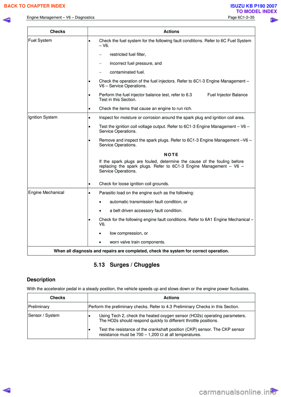
Checks Actions
Fuel System
• Check the fuel system for the following fault conditions. Refer to 6C Fuel System
– V6.
− restricted fuel filter,
− incorrect fuel pressure, and
− contaminated fuel.
• Check the operation of the fuel injectors. Refer to 6C1-3 Engine Management –
V6 – Service Operations.
• Perform the fuel injector balance test, refer to 6.3 Fuel Injector Balance
Test in this Section.
• Check the items that cause an engine to run rich.
Ignition System
• Inspect for moisture or corrosion around the spark plug and ignition coil area.
• Test the ignition coil voltage output. Refer to 6C1-3 Engine Management – V6 –
Service Operations.
• Remove and inspect the spark plugs. Refer to 6C1-3 Engine Management –V6 –
Service Operations.
NOTE
If the spark plugs are fouled, determine the cause of the fouling before
replacing the spark plugs. Refer to 6C1-3 Engine Management – V6 –
Service Operations.
• Check for loose ignition coil grounds.
Engine Mechanical
• Parasitic load on the engine such as the following:
• automatic transmission fault condition, or
• a belt driven accessory fault condition.
• Check for the following engine fault conditions. Refer to 6A1 Engine Mechanical –
V6.
• low compression, or
• worn valve train components.
When all diagnosis and repairs are completed, check the system for correct operation.
5.13 Surges / Chuggles
Description
W ith the accelerator pedal in a steady position, the vehicle speeds up and slows down or the engine power fluctuates.
Checks Actions
Preliminary Perform the preliminary checks. Refer to 4.3 Preliminary Checks in this Section.
Sensor / System
• Using Tech 2, check the heated oxygen sensor (HO2s) operating parameters.
The HO2s should respond quickly to different throttle positions.
• Test the resistance of the crankshaft position (CKP) sensor. The CKP sensor
resistance must be 700 – 1,200 Ω at all temperatures.
BACK TO CHAPTER INDEX
TO MODEL INDEX
ISUZU KB P190 2007
Page 3314 of 6020
Engine Management – V6 – Diagnostics Page 6C1-2–36
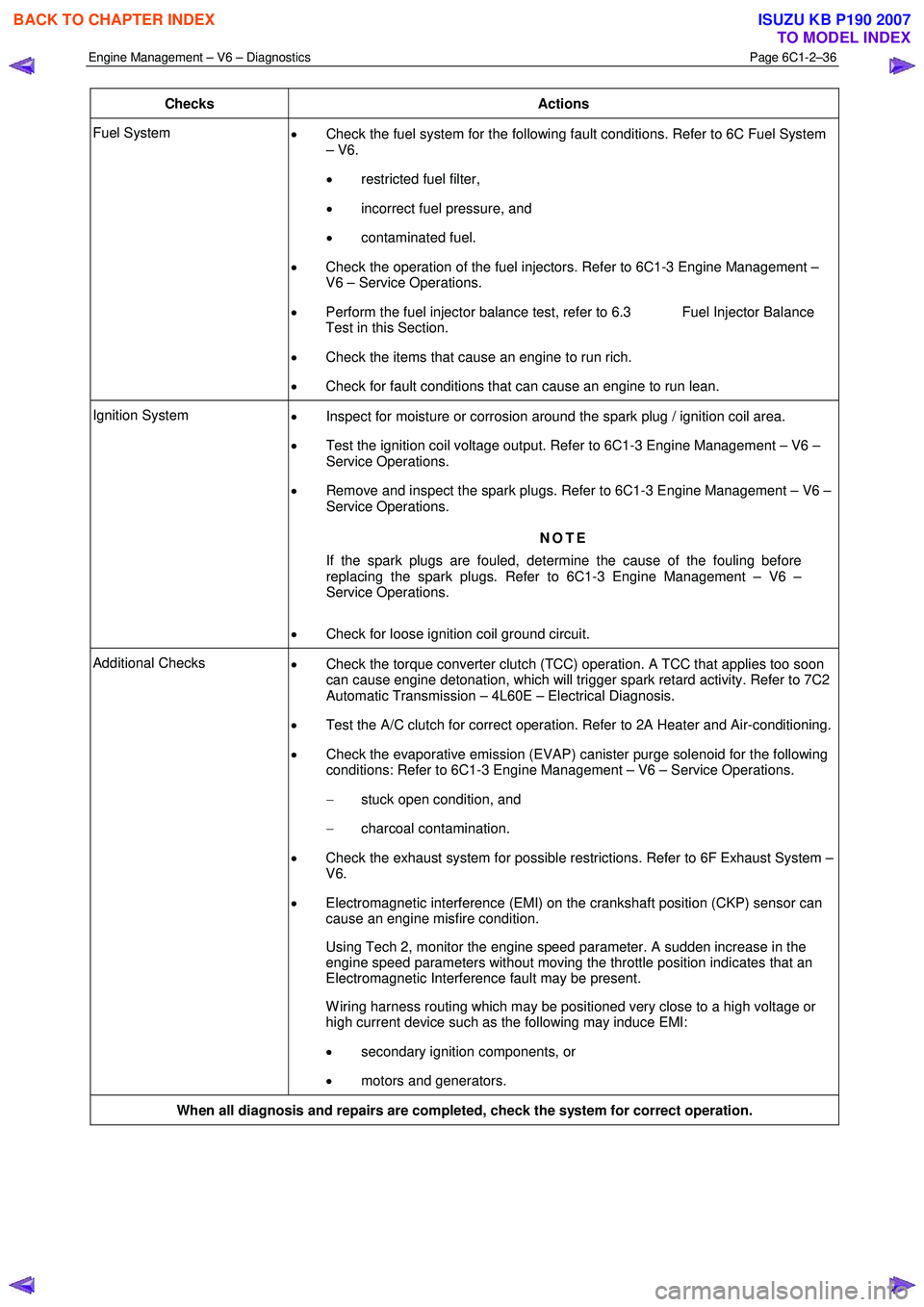
Checks Actions
Fuel System
• Check the fuel system for the following fault conditions. Refer to 6C Fuel System
– V6.
• restricted fuel filter,
• incorrect fuel pressure, and
• contaminated fuel.
• Check the operation of the fuel injectors. Refer to 6C1-3 Engine Management –
V6 – Service Operations.
• Perform the fuel injector balance test, refer to 6.3 Fuel Injector Balance
Test in this Section.
• Check the items that cause an engine to run rich.
• Check for fault conditions that can cause an engine to run lean.
Ignition System
• Inspect for moisture or corrosion around the spark plug / ignition coil area.
• Test the ignition coil voltage output. Refer to 6C1-3 Engine Management – V6 –
Service Operations.
• Remove and inspect the spark plugs. Refer to 6C1-3 Engine Management – V6 –
Service Operations.
NOTE
If the spark plugs are fouled, determine the cause of the fouling before
replacing the spark plugs. Refer to 6C1-3 Engine Management – V6 –
Service Operations.
• Check for loose ignition coil ground circuit.
Additional Checks
• Check the torque converter clutch (TCC) operation. A TCC that applies too soon
can cause engine detonation, which will trigger spark retard activity. Refer to 7C2
Automatic Transmission – 4L60E – Electrical Diagnosis.
• Test the A/C clutch for correct operation. Refer to 2A Heater and Air-conditioning.
• Check the evaporative emission (EVAP) canister purge solenoid for the following
conditions: Refer to 6C1-3 Engine Management – V6 – Service Operations.
− stuck open condition, and
− charcoal contamination.
• Check the exhaust system for possible restrictions. Refer to 6F Exhaust System –
V6.
• Electromagnetic interference (EMI) on the crankshaft position (CKP) sensor can
cause an engine misfire condition.
Using Tech 2, monitor the engine speed parameter. A sudden increase in the engine speed parameters without moving the throttle position indicates that an
Electromagnetic Interference fault may be present.
W iring harness routing which may be positioned very close to a high voltage or high current device such as the following may induce EMI:
• secondary ignition components, or
• motors and generators.
When all diagnosis and repairs are completed, check the system for correct operation.
BACK TO CHAPTER INDEX
TO MODEL INDEX
ISUZU KB P190 2007
Page 3382 of 6020

Engine Management – V6 – Diagnostics Page 6C1-2–104
Step Action Yes No
9 1 Inspect or test for the following conditions:
• Inspect the vacuum hoses for splits, kinks, and proper
connections.
• Inspect the throttle body and the intake manifold for
vacuum leaks.
• Inspect the crankcase ventilation valve and / or system for
any vacuum leaks.
• Test for the correct fuel pressure. Refer to 6C Fuel System
– V6.
• Inspect the fuel system for any restrictions, leaks or fuel
contamination. Refer to 6C Fuel System – V6.
• Inspect for fouled or damaged spark plugs. Determine
what caused the spark plugs to foul. Refer to 6C1-3
Engine Management – Service Operations.
• Inspect the exhaust system for restrictions. Refer to 6F
Exhaust System – V6.
• Inspect the engine control grounds for being clean, tight,
and in the correct location.
• Inspect for a camshaft actuator stuck in the full advance or
retard position.
2 Repair as required.
Did you find and correct the condition? Go to Step 10 Go to Symptoms in
6A1 Engine
Mechanical – V6
10 1 Use Tech 2 to clear the DTCs.
2 Switch off the ignition for 30 seconds.
3 Start the engine.
4 Operate the vehicle within the Conditions for Running DTC 300.
Did the DTC fail this ignition? Go to Step 2 Go to Step 11
11 1 Using Tech 2, select the DTC display function.
Does Tech display any DTCs? Go to the
appropriate DTC
Table in this Section System OK
When all diagnosis and repairs are completed, clear all DTCs and verify correct operation
7.17 DTC P0301, P0302, P0303, P0304, P0305
or P0306
DTC Descriptor
This diagnostic procedure supports the following DTCs:
• DTC P0301 – Cylinder 1 Misfire Detected
• DTC P0302 – Cylinder 2 Misfire Detected
• DTC P0303 – Cylinder 3 Misfire Detected
• DTC P0304 – Cylinder 4 Misfire Detected
• DTC P0305 – Cylinder 5 Misfire Detected
• DTC P0306 – Cylinder 6 Misfire Detected
BACK TO CHAPTER INDEX
TO MODEL INDEX
ISUZU KB P190 2007
Page 3384 of 6020
Engine Management – V6 – Diagnostics Page 6C1-2–106
− Damaged accessory drive belt
• For an intermittent condition, refer to 5.2 Intermittent Fault Conditions in this Section.
• Since a fault condition in a wiring connector may trigger DTCs, always test the connectors related to this
diagnostic procedure for shorted terminals or poor wiring connection before replacing any component. Refer to 8A
Electrical - Body and Chassis for information on electrical fault diagnosis.
• To assist diagnosis, refer to 3 W iring Diagrams and Connector Charts in this Section, for the system wiring
diagram and connector charts.
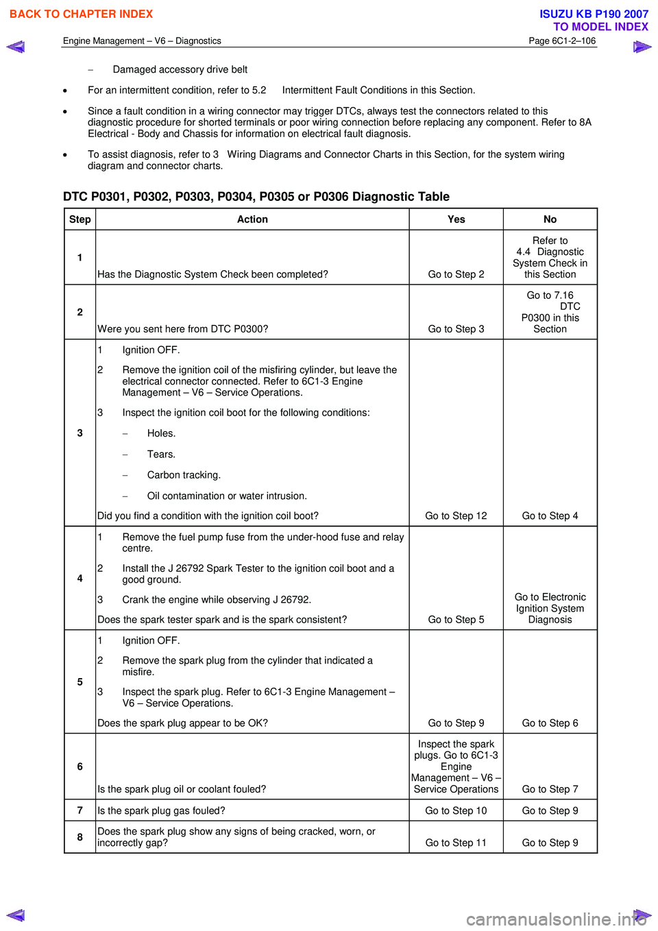
DTC P0301, P0302, P0303, P0304, P0305 or P0306 Diagnostic Table
Step Action Yes No
1
Has the Diagnostic System Check been completed? Go to Step 2 Refer to
4.4 Diagnostic
System Check in this Section
2
W ere you sent here from DTC P0300? Go to Step 3 Go to 7.16
DTC P0300 in this Section
3 1 Ignition OFF.
2 Remove the ignition coil of the misfiring cylinder, but leave the electrical connector connected. Refer to 6C1-3 Engine
Management – V6 – Service Operations.
3 Inspect the ignition coil boot for the following conditions:
− Holes.
− Tears.
− Carbon tracking.
− Oil contamination or water intrusion.
Did you find a condition with the ignition coil boot? Go to Step 12 Go to Step 4
4 1 Remove the fuel pump fuse from the under-hood fuse and relay
centre.
2 Install the J 26792 Spark Tester to the ignition coil boot and a good ground.
3 Crank the engine while observing J 26792.
Does the spark tester spark and is the spark consistent? Go to Step 5 Go to Electronic
Ignition System Diagnosis
5 1 Ignition OFF.
2 Remove the spark plug from the cylinder that indicated a misfire.
3 Inspect the spark plug. Refer to 6C1-3 Engine Management – V6 – Service Operations.
Does the spark plug appear to be OK? Go to Step 9 Go to Step 6
6
Is the spark plug oil or coolant fouled? Inspect the spark
plugs. Go to 6C1-3 Engine
Management – V6 – Service Operations Go to Step 7
7 Is the spark plug gas fouled? Go to Step 10 Go to Step 9
8 Does the spark plug show any signs of being cracked, worn, or
incorrectly gap? Go to Step 11 Go to Step 9
BACK TO CHAPTER INDEX
TO MODEL INDEX
ISUZU KB P190 2007
Page 3527 of 6020
Engine Management – V6 – Service Operations Page 6C1-3–3
2.21 Schrader Valve – Fuel Pressure Gauge Connection Point............................................................................... 47
Remove ................................................................................................................................................................. 47
Reinstall ................................................................................................................................................................ 47
2.22 Spark Plugs .................................................................................................................... ...................................... 48
Service Precautions............................................................................................................ ................................. 48
Remove ................................................................................................................................................................. 48
Inspect .................................................................................................................................................................. 48
Spark Plug Inspection .......................................................................................................... ............................... 49
Poor Spark Plug Performance.................................................................................................... ...................... 49
Analysis of Spark Plug Condition ..................................................................................................................... 51
Reinstall ................................................................................................................................................................ 53
2.23 Throttle Body Assembly......................................................................................................... ............................. 53
Handling Precautions .......................................................................................................................................... 53
Remove ................................................................................................................................................................. 53
Inspect .................................................................................................................................................................. 55
Reinstall ................................................................................................................................................................ 55
3 Specifications ................................................................................................................. ......................57
4 Assembly Lubricants ............................................................................................................ ...............60
5 Torque Specifications ..........................................................................................................................61
6 Special Tools ........................................................................................................................................62
BACK TO CHAPTER INDEX
TO MODEL INDEX
ISUZU KB P190 2007
Page 3572 of 6020
Engine Management – V6 – Service Operations Page 6C1-3–48
2.22 Spark Plugs
Service Precautions
1 Allow the engine to cool (to at least 50°C) before attempting to remove spark plugs. Attempting to remove spark
plugs from a hot engine may cause the plug / cylinder head threads to bind, resulting in tearing of the alloy cylinder
head threads.
2 Clean the spark plug recess area before removing any spark plug. Failure to do so could result in engine damage because of dirt or other foreign material entering the cylinder head or by the contamination of the cylinder head
threads. The contaminated threads may then prevent the correct seating of the new or replaced plug. If required,
use a thread chaser to clean the threads of any contamination where this is suspected.
3 Under no circumstances should the spark plug/s gap be adjusted. If the gap is not within specifications,
replace the spark plug.
Figure 6C1-3 – 66
Remove
1 Turn the ignition switch off.
2 Remove the ignition coil/s, refer to 2.15 Ignition Coil.
3 Using a suitable spark plug socket, loosen the spark plug slightly and then re-tighten to break away any carbon deposits on the threads.
Wear eye protection to avoid injury.
4 Loosen the spark plug once again one or two turns, then use compressed air to remove any foreign material that may otherwise enter the combustion chamber.
5 Remove the spark plug (1).
6 Repeat as required for the remaining spark plugs.
NOTE
Place each spark plug in the same order as that
of removal. This will enable any abnormal spark
plug condition to be identified with the cylinder.
NOTE
If the spark plugs are removed for an indefinite
period before installation, plug the spark plug
openings to prevent foreign particle ingress.
7 Repeat steps 2 to 5 for the remaining spark plugs as required.
Figure 6C1-3 – 67
Inspect
The spark plugs must not be re-gapped. If the gap of a spark plug is outside the specified range, replace the spark plug.
In addition, replace spark plugs that shows excessive dirt deposit or broken insulators.
BACK TO CHAPTER INDEX
TO MODEL INDEX
ISUZU KB P190 2007
Page 3573 of 6020
Engine Management – V6 – Service Operations Page 6C1-3–49
1 Replace any plug that has cracked and / or broken insulation or loose electrodes.
2 Inspect the spark plugs for defects. Refer to Analysis of Spark Plug Condition in this Section for identification of the condition of spark plugs.
3 Ensure the threads are clean and in good order.
4 Use a round wire feeler gauge to check the spark plug gap. If the gap is not within specifications, replace the
spark plug.
Spark plug gap ........................................... 1.1 – 1.2 mm
Figure 6C1-3 – 68
Spark Plug Inspection
Poor Spark Plug Performance
A spark plug can perform poorly due to wear, dirt, carbon fouling, excessive electrode wear, a broken insulator or
excessive gap.
Worn or Dirty Plugs
W orn or dirty plugs can give satisfactory operation while the vehicle is idling, but break down under load.
This can cause:
• poor fuel economy,
• power loss,
• acceleration loss,
• difficult starting, or
• poor engine performance.
Carbon Fouling
Carbon fouling is indicated by black carbon deposits. The black deposits are usually the result of slow-speed driving and
short runs. In these circumstances, the optimum engine operating temperature is seldom reached.
Fouling can also be caused by:
• worn piston rings,
• faulty ignition,
• rich fuel mixture, or
• spark plugs that are rated too cold.
Excessive Electrode Wear
This often indicates:
• the engine is operating at high speeds,
• the engine is operating at levels that are consistently greater than normal,
• a plug that is rated too hot,
• excessively lean fuel mixture, or
BACK TO CHAPTER INDEX
TO MODEL INDEX
ISUZU KB P190 2007