2007 ISUZU KB P190 service indicator
[x] Cancel search: service indicatorPage 3825 of 6020
Automatic Transmission – 4L60E – Electrical Diagnosis Page 7C2–39
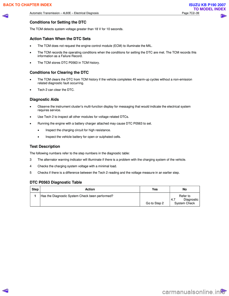
Conditions for Setting the DTC
The TCM detects system voltage greater than 18 V for 10 seconds.
Action Taken When the DTC Sets
•
The TCM does not request the engine control module (ECM) to illuminate the MIL.
• The TCM records the operating conditions when the conditions for setting the DTC are met. The TCM records this
information as a Failure Record.
• The TCM stores DTC P0563 in TCM history.
Conditions for Clearing the DTC
•
The TCM clears the DTC from TCM history if the vehicle completes 40 warm-up cycles without a non-emission
related diagnostic fault occurring.
• Tech 2 can clear the DTC.
Diagnostic Aids
• Observe the instrument cluster’s multi-function display for messaging that would indicate the electrical system
requires service.
• Use Tech 2 to inspect all other modules for voltage related DTCs.
• Running the engine with a battery charger attached may cause DTC P0563 to set.
• Inspect the charging circuit for high resistance.
• Inspect the vehicle battery for open or sulphated cells.
Test Description
The following numbers refer to the step numbers in the diagnostic table:
3 The alternator warning indicator will illuminate if there is a problem with the charging system of the vehicle.
4 Checks the charging system voltage with a minimal load.
5 Checks if there is a difference between the Tech 2 reading and the voltage measure in an earlier step.
DTC P0563 Diagnostic Table
Step Action Yes No
1 Has the Diagnostic System Check been performed?
Go to Step 2 Refer to
4.7 Diagnostic System Check
BACK TO CHAPTER INDEX
TO MODEL INDEX
ISUZU KB P190 2007
Page 3967 of 6020
TRANSMISSION CONTROL SYSTEM (AW30–40LE) 7A2-1
SECTION 7A2
TRANSMISSION CONTROL SYSTEM (AW30–40LE)
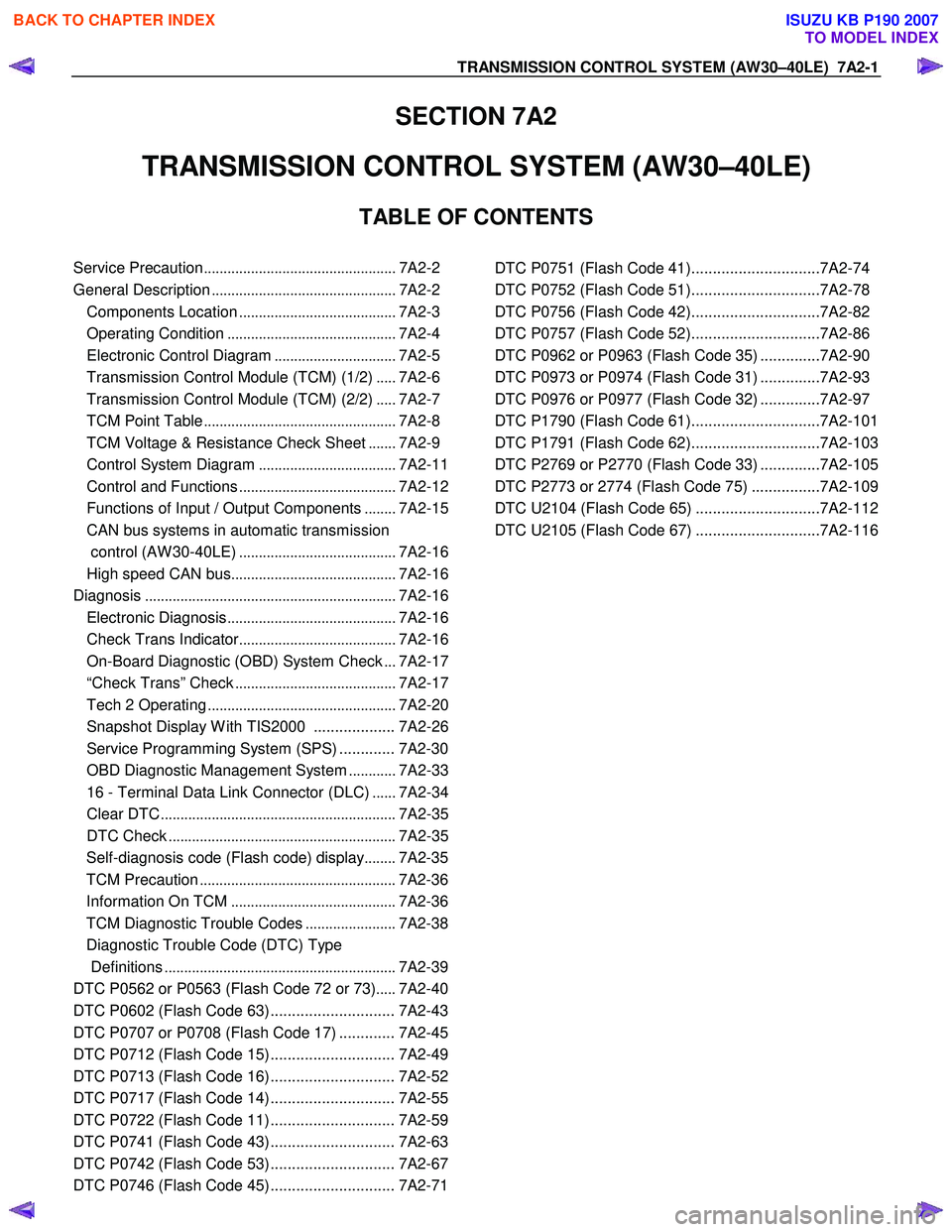
TABLE OF CONTENTS
Service Precaution ................................................. 7A2-2
General Description ............................................... 7A2-2
Components Location ........................................ 7A2-3
Operating Condition ........................................... 7A2-4
Electronic Control Diagram ...............................7A2-5
Transmission Control Module (TCM) (1/2) .....7A2-6
Transmission Control Module (TCM) (2/2) .....7A2-7
TCM Point Table ................................................. 7A2-8
TCM Voltage & Resistance Check Sheet .......7A2-9
Control System Diagram ...................................7A2-11
Control and Functions ........................................ 7A2-12
Functions of Input / Output Components ........7A2-15
CAN bus systems in automatic transmission
control (AW 30-40LE) ........................................ 7A2-16
High speed CAN bus .......................................... 7A2-16
Diagnosis ................................................................ 7A2-16
Electronic Diagnosis ........................................... 7A2-16
Check Trans Indicator ........................................ 7A2-16
On-Board Diagnostic (OBD) System Check ...7A2-17
“Check Trans” Check ......................................... 7A2-17
Tech 2 Operating ................................................ 7A2-20
Snapshot Display W ith TIS2000 ................... 7A2-26
Service Programming System (SPS) ............. 7A2-30
OBD Diagnostic Management System ............7A2-33
16 - Terminal Data Link Connector (DLC) ......7A2-34
Clear DTC ............................................................ 7A2-35
DTC Check .......................................................... 7A2-35
Self-diagnosis code (Flash code) display ........7A2-35
TCM Precaution .................................................. 7A2-36
Information On TCM .......................................... 7A2-36
TCM Diagnostic Trouble Codes .......................7A2-38
Diagnostic Trouble Code (DTC) Type
Definitions ........................................................... 7A2-39
DTC P0562 or P0563 (Flash Code 72 or 73) .....7A2-40
DTC P0602 (Flash Code 63) ............................. 7A2-43
DTC P0707 or P0708 (Flash Code 17) ............. 7A2-45
DTC P0712 (Flash Code 15) ............................. 7A2-49
DTC P0713 (Flash Code 16) ............................. 7A2-52
DTC P0717 (Flash Code 14) ............................. 7A2-55
DTC P0722 (Flash Code 11) ............................. 7A2-59
DTC P0741 (Flash Code 43) ............................. 7A2-63
DTC P0742 (Flash Code 53) ............................. 7A2-67
DTC P0746 (Flash Code 45) ............................. 7A2-71
DTC P0751 (Flash Code 41)..............................7A2-74
DTC P0752 (Flash Code 51)..............................7A2-78
DTC P0756 (Flash Code 42)..............................7A2-82
DTC P0757 (Flash Code 52)..............................7A2-86
DTC P0962 or P0963 (Flash Code 35) ..............7A2-90
DTC P0973 or P0974 (Flash Code 31) ..............7A2-93
DTC P0976 or P0977 (Flash Code 32) ..............7A2-97
DTC P1790 (Flash Code 61)..............................7A2-101
DTC P1791 (Flash Code 62)..............................7A2-103
DTC P2769 or P2770 (Flash Code 33) ..............7A2-105
DTC P2773 or 2774 (Flash Code 75) ................7A2-109
DTC U2104 (Flash Code 65) .............................7A2-112
DTC U2105 (Flash Code 67) .............................7A2-116
BACK TO CHAPTER INDEX
TO MODEL INDEX
ISUZU KB P190 2007
Page 4110 of 6020
ON-VEHICLE SERVICE (AW30–40LE) 7A3-25
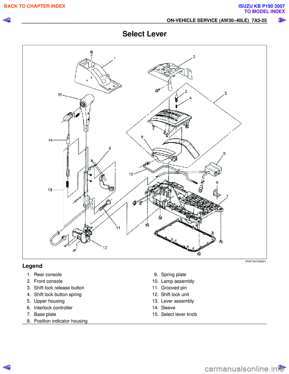
Select Lever
RTW 77ALF000201
Legend
1. Rear console
2. Front console
3. Shift lock release button
4. Shift lock button spring 5. Upper housing
6. Interlock controller
7. Base plate
8. Position indicator housing
9. Spring plate
10. Lamp assembly
11. Grooved pin
12. Shift lock unit
13. Lever assembly
14. Sleeve
15. Select lever knob
BACK TO CHAPTER INDEX
TO MODEL INDEX
ISUZU KB P190 2007
Page 4111 of 6020
7A3-26 ON-VEHICLE SERVICE (AW30–40LE)
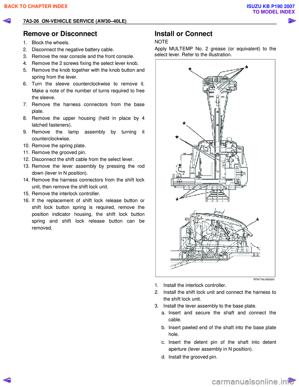
Remove or Disconnect
1. Block the wheels.
2. Disconnect the negative battery cable.
3. Remove the rear console and the front console.
4. Remove the 2 screws fixing the select lever knob.
5. Remove the knob together with the knob button and spring from the lever.
6. Turn the sleeve counterclockwise to remove it. Make a note of the number of turns required to free
the sleeve.
7. Remove the harness connectors from the base plate.
8. Remove the upper housing (held in place by 4 latched fasteners).
9. Remove the lamp assembly by turning it counterclockwise.
10. Remove the spring plate.
11. Remove the grooved pin.
12. Disconnect the shift cable from the select lever.
13. Remove the lever assembly by pressing the rod down (lever in N position).
14. Remove the harness connectors from the shift lock unit, then remove the shift lock unit.
15. Remove the interlock controller.
16. If the replacement of shift lock release button o
r
shift lock button spring is required, remove the
position indicator housing, the shift lock button
spring and shift lock release button can be
removed.
Install or Connect
NOTE
Apply MULTEMP No. 2 grease (or equivalent) to the
select lever. Refer to the illustration.
RTW 77ALH000201
1. Install the interlock controller.
2. Install the shift lock unit and connect the harness to the shift lock unit.
3. Install the lever assembly to the base plate. a. Insert and secure the shaft and connect the cable.
b. Insert pawled end of the shaft into the base plate hole.
c. Insert the detent pin of the shaft into detent aperture (lever assembly in N position).
d. Install the grooved pin.
BACK TO CHAPTER INDEX
TO MODEL INDEX
ISUZU KB P190 2007
Page 4404 of 6020
7A2-120 TRANSMISSION CONTROL SYSTEM (JR405E)
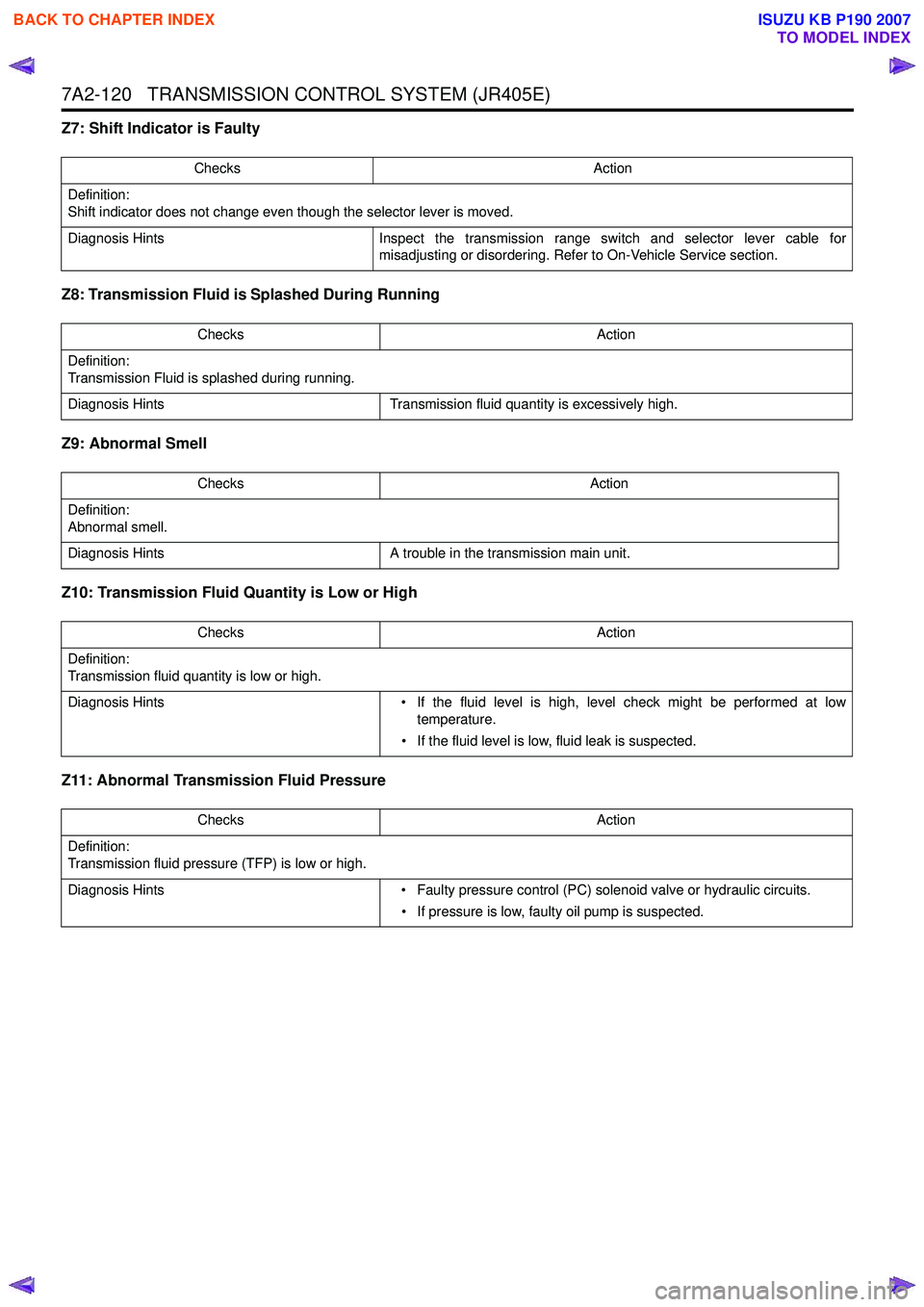
Z7: Shift Indicator is Faulty
Z8: Transmission Fluid is Splashed During Running
Z9: Abnormal Smell
Z10: Transmission Fluid Quantity is Low or High
Z11: Abnormal Transmission Fluid Pressure
Checks Action
Definition:
Shift indicator does not change even though the selector lever is moved.
Diagnosis Hints Inspect the transmission range switch and selector lever cable for
misadjusting or disordering. Refer to On-Vehicle Service section.
Checks Action
Definition:
Transmission Fluid is splashed during running.
Diagnosis Hints Transmission fluid quantity is excessively high.
Checks Action
Definition:
Abnormal smell.
Diagnosis Hints A trouble in the transmission main unit.
Checks Action
Definition:
Transmission fluid quantity is low or high.
Diagnosis Hints • If the fluid level is high, level check might be performed at low
temperature.
• If the fluid level is low, fluid leak is suspected.
Checks Action
Definition:
Transmission fluid pressure (TFP) is low or high.
Diagnosis Hints • Faulty pressure control (PC) solenoid valve or hydraulic circuits.
• If pressure is low, faulty oil pump is suspected.
BACK TO CHAPTER INDEX
TO MODEL INDEX
ISUZU KB P190 2007
Page 4464 of 6020

7A3-10 ON-VEHICLE SERVICE (JR405E)
SELECT LEVER
RTW 77ALF000201
Legend
1. Rear console
2. Front console
3. Shift lock release button
4. Shift lock button spring 5. Upper housing
6. Interlock controller
7. Base plate
8. Position indicator housing
9. Spring plate
10. Lamp assembly
11. Grooved pin
12. Shift lock unit
13. Lever assembly
14. Sleeve
15. Select lever knob
BACK TO CHAPTER INDEX
TO MODEL INDEX
ISUZU KB P190 2007
Page 4465 of 6020
ON-VEHICLE SERVICE (JR405E) 7A3-11
Remove or Disconnect
1. Block the wheels.
2. Disconnect the negative battery cable.
3. Remove the rear console and the front console.
4. Remove the 2 screws fixing the select lever knob.
5. Remove the knob together with the knob button and spring from the lever.
6. Turn the sleeve counterclockwise to remove it. Make a note of the number of turns required to free
the sleeve.
7. Remove the harness connectors from the base plate.
8. Remove the upper housing (held in place by 4 latched fasteners).
9. Remove the lamp assembly by turning it counterclockwise.
10. Remove the spring plate.
11. Remove the grooved pin.
12. Disconnect the shift cable from the select lever.
13. Remove the lever assembly by pressing the rod down (lever in N position).
14. Remove the harness connectors from the shift lock unit, then remove the shift lock unit.
15. Remove the interlock controller.
16. If the replacement of shift lock release button o
r
shift lock button spring is required, remove the
position indicator housing, the shift lock button
spring and shift lock release button can be
removed.
Install or Connect
NOTE
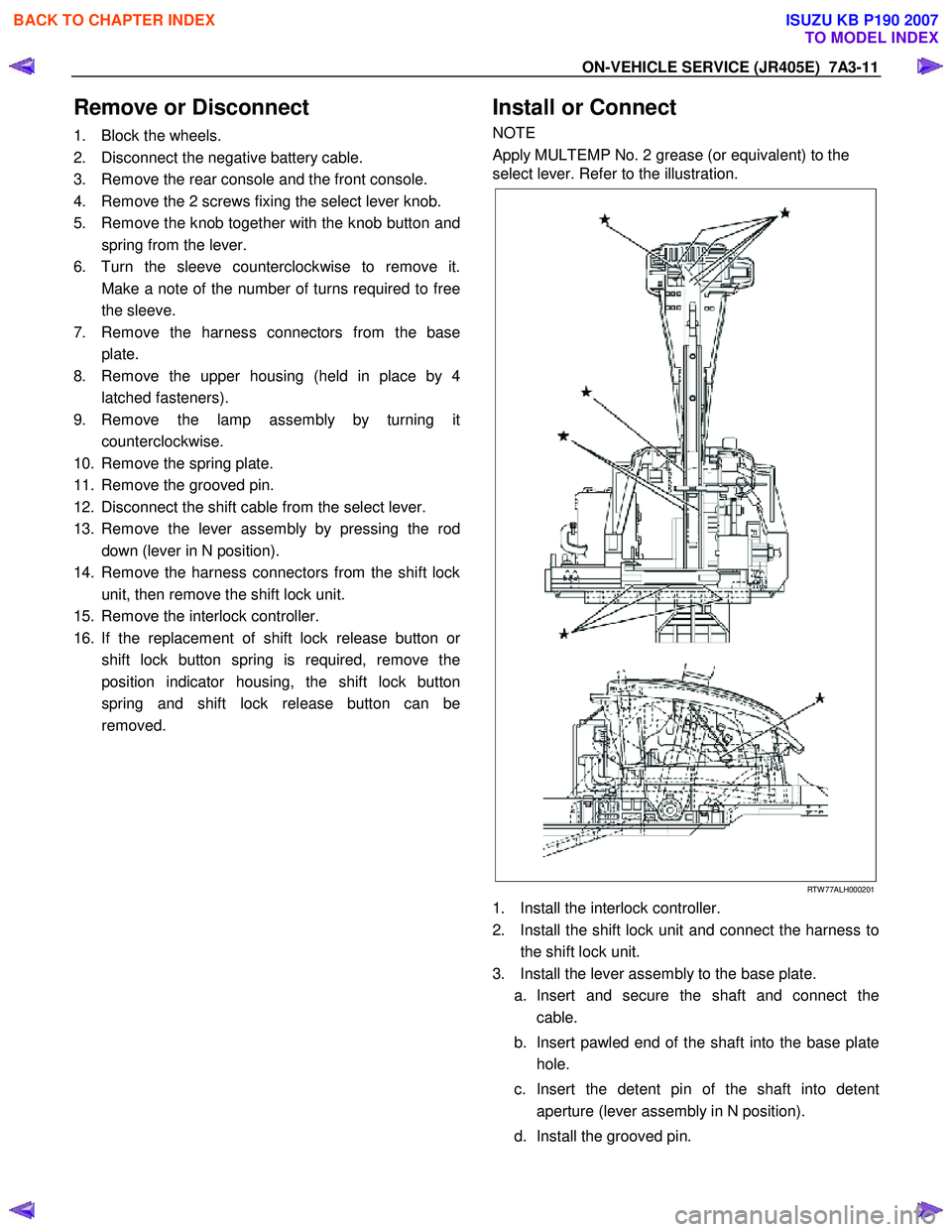
Apply MULTEMP No. 2 grease (or equivalent) to the
select lever. Refer to the illustration.
RTW 77ALH000201
1. Install the interlock controller.
2. Install the shift lock unit and connect the harness to the shift lock unit.
3. Install the lever assembly to the base plate. a. Insert and secure the shaft and connect the cable.
b. Insert pawled end of the shaft into the base plate hole.
c. Insert the detent pin of the shaft into detent aperture (lever assembly in N position).
d. Install the grooved pin.
BACK TO CHAPTER INDEX
TO MODEL INDEX
ISUZU KB P190 2007
Page 4875 of 6020
TRANSFER CONTROL SYSTEM 7D1-1
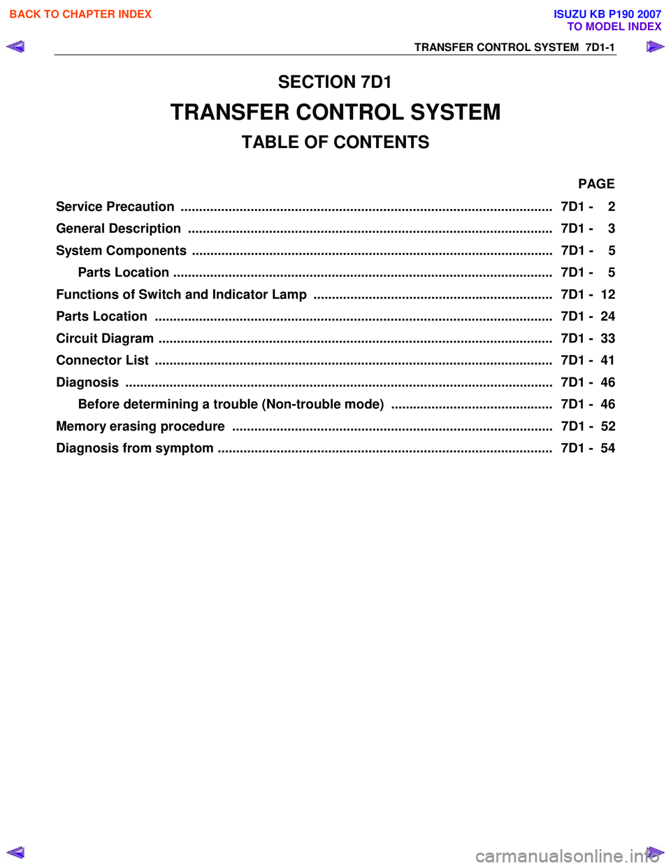
SECTION 7D1
TRANSFER CONTROL SYSTEM
TABLE OF CONTENTS
PAGE
Service Precaution ..................................................................................................... 7D1 - 2
General Description ................................................................................................... 7D1 - 3
System Components .................................................................................................. 7D1 - 5 Parts Location ....................................................................................................... 7D1 - 5
Functions of Switch and Indicator Lamp ................................................................. 7D1 - 12
Parts Location ............................................................................................................ 7D1 - 24
Circuit Diagram ........................................................................................................... 7D1 - 33
Connector List ............................................................................................................ 7D1 - 41
Diagnosis .................................................................................................................... 7D1 - 46
Before determining a trouble (Non-trouble mode) ............................................ 7D1 - 46
Memory erasing procedure ....................................................................................... 7D1 - 52
Diagnosis from symptom ........................................................................................... 7D1 - 54
BACK TO CHAPTER INDEX
TO MODEL INDEX
ISUZU KB P190 2007