2007 ISUZU KB P190 ignition
[x] Cancel search: ignitionPage 678 of 6020

BRAKE CONTROL SYSTEM 5A-85
Step Action Value(s) Yes No
4 1. Ignition "OFF".
2. Check for a poor condition at the EHCU harness connector.
3. Check the EHCU circuit for an open, short to ground, or short to voltage. Also, check the EHCU
ignition feed circuit for an open or short to ground
and the EHCU ground circuit for an open or short to
voltage.
4. If a problem is found, repair as necessary. W as a problem found? - Verify repair Go to Step 9
5 1. Ignition "OFF", disconnect the EHCU and G sensor.
2. Check the circuit between EHCU and G sensor. (short to ground, or short to voltage.)
3. If a problem is found, repair as necessary. W as a problem found? - Verify repair
Go to Step 6 Go to Step 6
6 1. Remove the G sensor. 2. Reconnect G sensor and EHCU
3. Install the Tech 2.
4. Ignition "ON", engine "OFF".
5. Observe the G sensor reading on Tech 2. If G sensor inclines, reading voltage will change.
Is the reading voltage between specified values? 1.0 – 4.0 V Go to Step 7 Go to Step 8
7 1. Ignition "OFF". 2. Install the G sensor.
3. Install the Tech 2.
4. Ignition "ON", engine "OFF".
5. Select "Display DTCs" with the Tech 2. Are any DTCs stored? - Go to Step 8 Verify repair
8 1. Replace G sensor.
2. Select "Display DTCs" with the Tech 2. Note: Perform the various tests (actuator test, test
run, brake test, etc.) then observe the DTC with a
Tech 2.
Are any DTCs stored? - Go to Step 9 Verify repair
9 Replace EHCU.
Note: Check the EHCU type for specification, when
the EHCU is replaced.
(Specification ; 2W D model or 4W D model)
Is the action complete? - Verify repair -
BACK TO CHAPTER INDEX
TO MODEL INDEX
ISUZU KB P190 2007
Page 771 of 6020

PARKING BRAKE SYSTEM 5D-1
Service Precaution
Service Precaution
WARNING: THIS VEHICLE HAS A SUPPLEMENTAL
RESTRAINT SYSTEM (SRS). REFER TO THE SRS
COMPONENT AND WIRING LOCATION VIEW IN
ORDER TO DETERMINE WHETHER YOU ARE
PERFORMING SERVICE ON OR NEAR THE SRS
COMPONENTS OR THE SRS WIRING. WHEN YOU
ARE PERFORMING SERVICE ON OR NEAR THE
SRS COMPONENTS OR THE SRS WIRING, REFER
TO THE SRS SERVICE INFORMATION. FAILURE TO
FOLLOW WARNINGS COULD RESULT IN
POSSIBLE AIR BAG DEPLOYMENT, PERSONAL
INJURY, OR OTHERWISE UNNECESSARY SRS
SYSTEM REPAIRS.
CAUTION: Always use the correct fastener in the
proper location. When you replace a fastener, use
ONLY the exact part number for that application.
ISUZU/GM will call out those fasteners that require
a replacement after removal. ISUZU/GM will also
call out the fasteners that require thread lockers o
r
thread sealant. UNLESS OTHERWISE SPECIFIED,
do not use supplemental coatings (paints, greases,
or other corrosion inhibitors) on threaded fasteners
or fastener joint interfaces. Generally, such
coatings adversely affect the fastener torque and
the joint clamping force, and may damage the
fastener. When you install fasteners, use the
correct tightening sequence and specifications.
Following these instructions can help you avoid
damage to parts and systems.
General Description
Pulling up the parking brake lever by hand will set the
parking brake. By means of a ratchet type lock, the
lever can be held in that position until it is released. The
position of the lever is transmitted through cable/leve
r
systems to the rear wheels. These parts are designed
to obtain sufficient braking force even when parking on
slopes. W hen the parking brake is set, or when the
ignition SW is in the “ON” position, the brake warning
light illuminates. The rear wheel parking brake is a
leading-trailing brake (mechanical inside expansion
type) built in the rear drum brake. Parking brake
adjustment is made through the adjusting hole (bored
through back plate). Parking brake lever stroke should
be adjusted to 8 −14 notches with 294N (30 kg / 66 lb)
(bench seat) or 6 −9 notches with 294N (30 kg / 66 lb)
(bucket seat). Refer to “Parking Brake Adjustment” in
this section.
BACK TO CHAPTER INDEX
TO MODEL INDEX
ISUZU KB P190 2007
Page 831 of 6020

6A – 26 ENGINE MECHANICAL
041RY00011
Draining Procedure
The indicator light will come on when the water level in the
water separator exceeds the specified level.
Drain the water and foreign material from the water
separator (inside chassis frame) with the following
procedure.
1. Place the drain pan under the drain plug.
2. Loosen the drain plug and drain water.
3. After draining the water, tighten the drain plug.
4. Operate the priming pump on the fuel filter several times and check for fuel leakage.
5. Check the water separator indicator light. It should be off.
Except EURO III model
RTW 46ASH002901
For EURO III model
RTW 46ASH000501
Air Bleeding
1. Operate the priming pump until strong resistance is felt.
2. W ait 1 minute, and operate the priming pump until strong resistance is felt.
3. Once more wait, and operate the priming pump until strong resistance is felt.
4. Turn the ignition switch to the "ON" position. W ait until the glow indicator lamp turns off.
5. Turn the ignition switch to the "START" position and crank the engine until it starts.
6. If the engine does not start, repeat Step 3 - 5.
7. Allow the engine to idle for 3 minutes to bleed air completely form the fuel system and check for fuel
leakage.
Note:
Insufficient air bleeding may cause the Diagnostic
Trouble Code (DTC) store or improper engine
performance.
BACK TO CHAPTER INDEX
TO MODEL INDEX
ISUZU KB P190 2007
Page 1056 of 6020
6E-22 Engine Control System (4JH1)
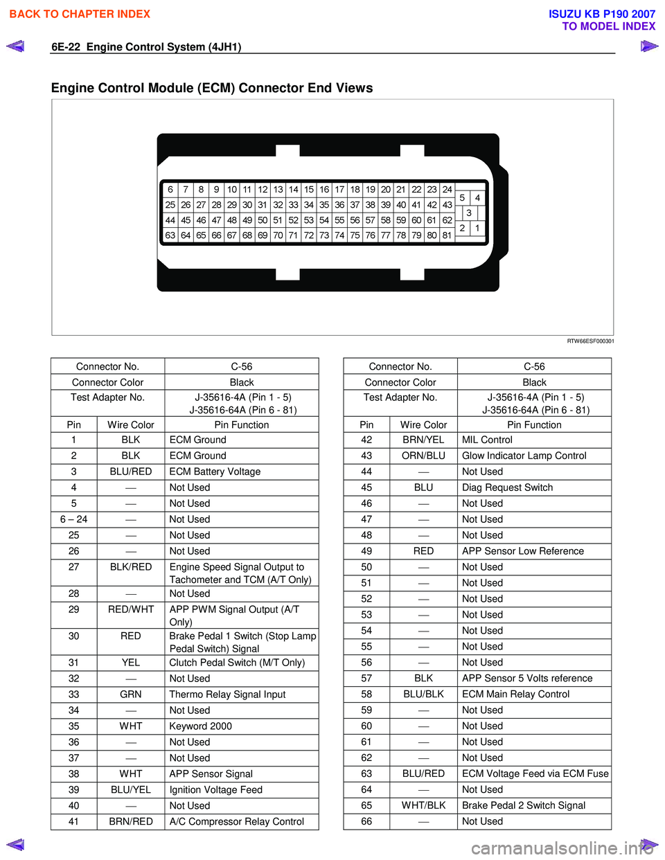
Engine Control Module (ECM) Connector End Views
RTW 66ESF000301
Connector No. C-56
Connector Color Black
Test Adapter No. J-35616-4A (Pin 1 - 5)
J-35616-64A (Pin 6 - 81)
Pin W ire Color Pin Function
1 BLK ECM Ground
2 BLK ECM Ground
3 BLU/RED ECM Battery Voltage
4 Not Used
5 Not Used
6 – 24 Not Used
25 Not Used
26 Not Used
27 BLK/RED Engine Speed Signal Output to
Tachometer and TCM (A/T Only)
28 Not Used
29 RED/W HT APP PW M Signal Output (A/T
Only)
30 RED Brake Pedal 1 Switch (Stop Lamp Pedal Switch) Signal
31 YEL Clutch Pedal Switch (M/T Only)
32 Not Used
33 GRN Thermo Relay Signal Input
34 Not Used
35 W HT Keyword 2000
36 Not Used
37 Not Used
38 W HT APP Sensor Signal
39 BLU/YEL Ignition Voltage Feed
40 Not Used
41 BRN/RED A/C Compressor Relay Control
Connector No. C-56
Connector Color Black
Test Adapter No. J-35616-4A (Pin 1 - 5)
J-35616-64A (Pin 6 - 81)
Pin W ire Color Pin Function
42 BRN/YEL MIL Control
43 ORN/BLU Glow Indicator Lamp Control
44 Not Used
45 BLU Diag Request Switch
46 Not Used
47 Not Used
48 Not Used
49 RED APP Sensor Low Reference
50 Not Used
51 Not Used
52 Not Used
53 Not Used
54 Not Used
55 Not Used
56 Not Used
57 BLK APP Sensor 5 Volts reference
58 BLU/BLK ECM Main Relay Control
59 Not Used
60 Not Used
61 Not Used
62 Not Used
63 BLU/RED ECM Voltage Feed via ECM Fuse
64 Not Used
65 W HT/BLK Brake Pedal 2 Switch Signal
66 Not Used
BACK TO CHAPTER INDEX
TO MODEL INDEX
ISUZU KB P190 2007
Page 1059 of 6020
Engine Control System (4JH1) 6E-25
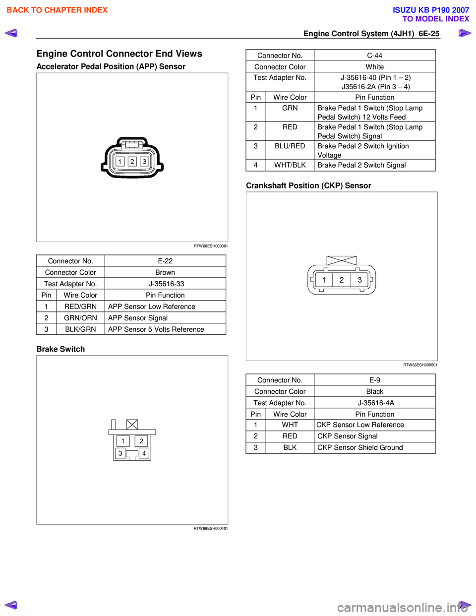
Engine Control Connector End Views
Accelerator Pedal Position (APP) Sensor
RTW 66ESH000301
Connector No. E-22
Connector Color Brown
Test Adapter No. J-35616-33
Pin W ire Color Pin Function
1 RED/GRN APP Sensor Low Reference
2 GRN/ORN APP Sensor Signal
3 BLK/GRN APP Sensor 5 Volts Reference
Brake Switch
RTW 66ESH000401
Connector No. C-44
Connector Color W hite
Test Adapter No. J-35616-40 (Pin 1 – 2)
J35616-2A (Pin 3 – 4)
Pin W ire Color Pin Function
1 GRN Brake Pedal 1 Switch (Stop Lamp
Pedal Switch) 12 Volts Feed
2 RED Brake Pedal 1 Switch (Stop Lamp Pedal Switch) Signal
3 BLU/RED Brake Pedal 2 Switch Ignition Voltage
4 W HT/BLK Brake Pedal 2 Switch Signal
Crankshaft Position (CKP) Sensor
RTW 66ESH000501
Connector No. E-9
Connector Color Black
Test Adapter No. J-35616-4A
Pin W ire Color Pin Function
1 W HT CKP Sensor Low Reference
2 RED CKP Sensor Signal
3 BLK CKP Sensor Shield Ground
BACK TO CHAPTER INDEX
TO MODEL INDEX
ISUZU KB P190 2007
Page 1060 of 6020
6E-26 Engine Control System (4JH1)
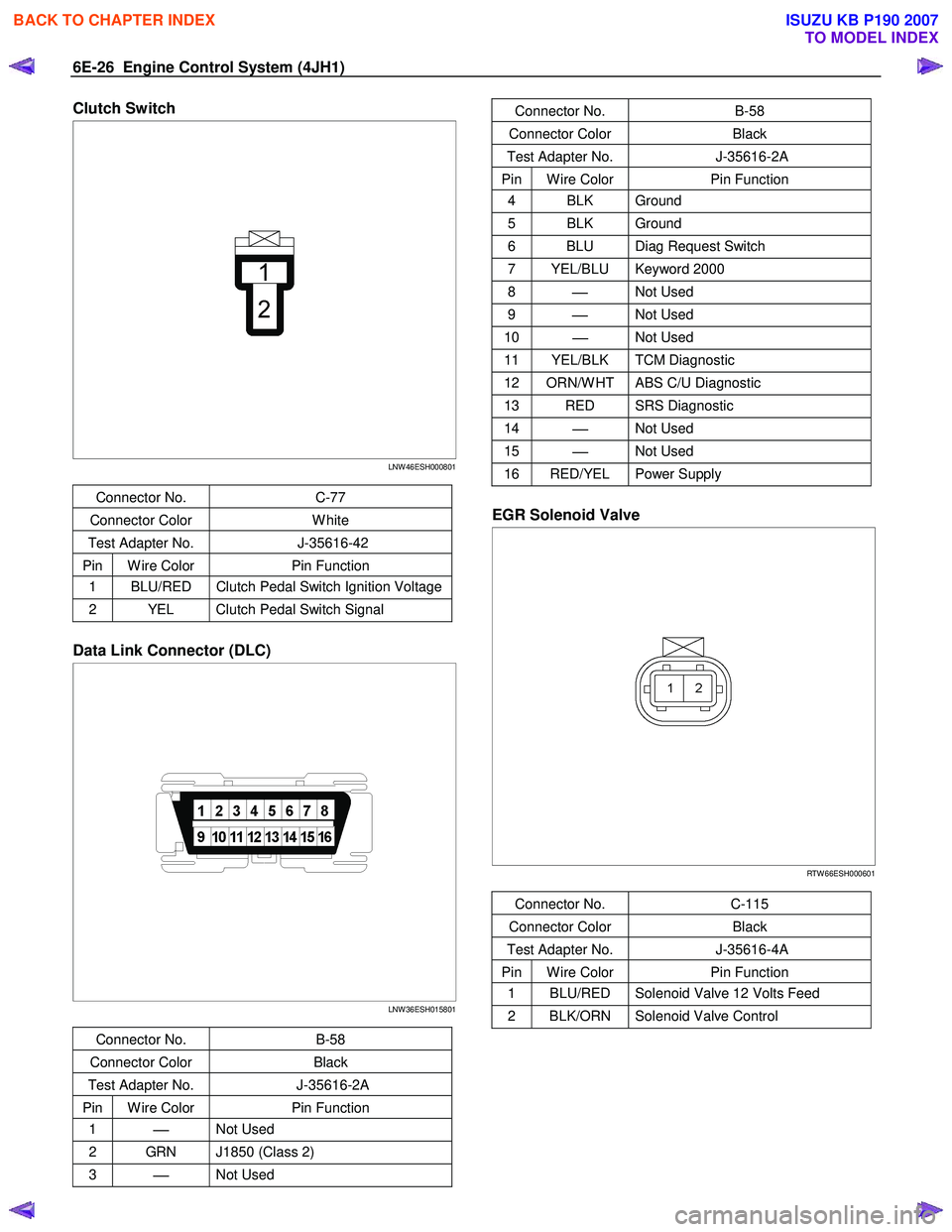
Clutch Switch
LNW 46ESH000801
Connector No. C-77
Connector Color W hite
Test Adapter No. J-35616-42
Pin W ire Color Pin Function
1 BLU/RED Clutch Pedal Switch Ignition Voltage
2 YEL Clutch Pedal Switch Signal
Data Link Connector (DLC)
LNW 36ESH015801
Connector No. B-58
Connector Color Black
Test Adapter No. J-35616-2A
Pin W ire Color Pin Function
1
Not Used
2 GRN J1850 (Class 2)
3
Not Used
Connector No. B-58
Connector Color Black
Test Adapter No. J-35616-2A
Pin W ire Color Pin Function
4 BLK Ground
5 BLK Ground
6 BLU Diag Request Switch
7 YEL/BLU Keyword 2000
8
Not Used
9
Not Used
10
Not Used
11 YEL/BLK TCM Diagnostic
12 ORN/W HT ABS C/U Diagnostic
13 RED SRS Diagnostic
14
Not Used
15
Not Used
16 RED/YEL Power Supply
EGR Solenoid Valve
RTW 66ESH000601
Connector No. C-115
Connector Color Black
Test Adapter No. J-35616-4A
Pin W ire Color Pin Function
1 BLU/RED Solenoid Valve 12 Volts Feed
2 BLK/ORN Solenoid Valve Control
BACK TO CHAPTER INDEX
TO MODEL INDEX
ISUZU KB P190 2007
Page 1062 of 6020
6E-28 Engine Control System (4JH1)
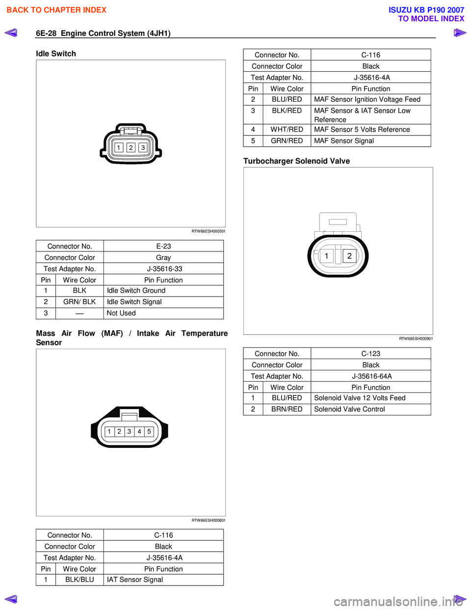
Idle Switch
RTW 66ESH000301
Connector No. E-23
Connector Color Gray
Test Adapter No. J-35616-33
Pin W ire Color Pin Function
1 BLK Idle Switch Ground
2 GRN/ BLK Idle Switch Signal
3
Not Used
Mass Air Flow (MAF) / Intake Air Temperature
Sensor
RTW 66ESH000801
Connector No. C-116
Connector Color Black
Test Adapter No. J-35616-4A
Pin W ire Color Pin Function
1 BLK/BLU IAT Sensor Signal
Connector No. C-116
Connector Color Black
Test Adapter No. J-35616-4A
Pin W ire Color Pin Function
2 BLU/RED MAF Sensor Ignition Voltage Feed
3 BLK/RED MAF Sensor & IAT Sensor Low
Reference
4 W HT/RED MAF Sensor 5 Volts Reference
5 GRN/RED MAF Sensor Signal
Turbocharger Solenoid Valve
RTW 66ESH000901
Connector No. C-123
Connector Color Black
Test Adapter No. J-35616-64A
Pin W ire Color Pin Function
1 BLU/RED Solenoid Valve 12 Volts Feed
2 BRN/RED Solenoid Valve Control
BACK TO CHAPTER INDEX
TO MODEL INDEX
ISUZU KB P190 2007
Page 1065 of 6020
Engine Control System (4JH1) 6E-31
Diagnostic Starting Point - Engine Controls
Begin the system diagnosis with Diagnostic System
Check - Engine Controls. The Diagnostic System Check
- Engine Controls will provide the following information:
• The identification of the control modules which
command the system.
• The ability of the control modules to communicate
through the serial data circuit.
• The identification of any stored diagnostic trouble
codes (DTCs) and the their statuses.
The use of the Diagnostic System Check - Engine
Controls will identify the correct procedure fo
r
diagnosing the system and where the procedure is
located.
Important:
Engine Control System Check Sheet must be used to
verify the complaint vehicle, you need to know the
correct (normal) operating behavior of the system and
verify that the customer complaint is a valid failure o
f
the system.
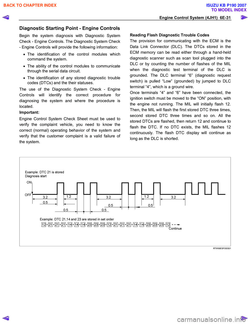
Reading Flash Diagnostic Trouble Codes
The provision for communicating with the ECM is the
Data Link Connector (DLC). The DTCs stored in the
ECM memory can be read either through a hand-held
diagnostic scanner such as scan tool plugged into the
DLC or by counting the number of flashes of the MIL
when the diagnostic test terminal of the DLC is
grounded. The DLC terminal “6” (diagnostic request
switch) is pulled “Low” (grounded) by jumped to DLC
terminal “4”, which is a ground wire.
Once terminals “4” and “6” have been connected, the
ignition switch must be moved to the “ON” position, with
the engine not running. The MIL will initially flash 12.
Then, the MIL will flash the first stored DTC three times,
second stored DTC three times and so on. All the
stored DTCs are flashed, then return 12 and continue to
flash the DTC. If no DTC exists, the MIL flashes 12
continuously. The flash DTC display will continue as
long as the DLC is shorted.
RTW 66ESF000501
BACK TO CHAPTER INDEX
TO MODEL INDEX
ISUZU KB P190 2007