2007 ISUZU KB P190 fuse box
[x] Cancel search: fuse boxPage 5424 of 6020
8A-486 ELECTRICAL-BODY AND CHASSIS
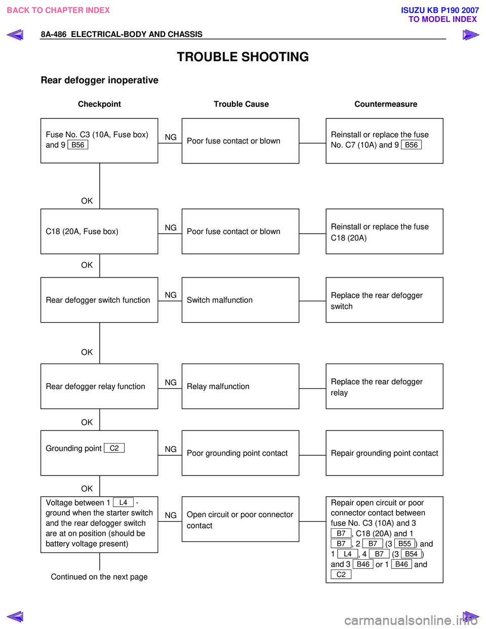
TROUBLE SHOOTING
Rear defogger inoperative
Checkpoint Trouble Cause Countermeasure
Reinstall or replace the fuse
No. C7 (10A) and 9
B56
Poor fuse contact or blown
NG
Reinstall or replace the fuse
C18 (20A)
C18 (20A, Fuse box)
Poor fuse contact or blown
Replace the rear defogger
switch
Rear defogger switch function
Switch malfunction
NG
NG
OK
OK
OK
Fuse No. C3 (10A, Fuse box)
and 9
B56
Replace the rear defogger
relay
Relay malfunction
NG
Continued on the next page
Rear defogger relay function
Repair grounding point contact
Grounding point
C2
Poor grounding point contact
NG
OK
Repair open circuit or poor
connector contact between
fuse No. C3 (10A) and 3
B7 , C18 (20A) and 1
B7 , 2 B7 (3 B55) and
1
L4 , 4 B7 (3 B54)
and 3
B46 or 1 B46 and
C2
Voltage between 1 L4 -
ground when the starter switch
and the rear defogger switch
are at on position (should be
battery voltage present)
Open circuit or poor connector
contact
NG
OK
BACK TO CHAPTER INDEX
TO MODEL INDEXISUZU KB P190 2007
Page 5561 of 6020
ELECTRICAL-BODY AND CHASSIS 8A-623
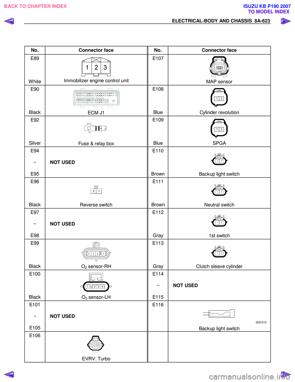
No. Connector face No. Connector face
E89
White
Immobilizer engine control unit E107
MAP sensor
E90
Black
ECM J1 E108
Blue Cylinder revolution
E92
Silver
Fuse & relay box E109
Blue SPGA
E94
~
E95 NOT USED E110
Brown
Backup light switch
E96
Black
Reverse switch E111
BrownNeutral switch
E97
~
E98 NOT USED E112
Gray
1st switch
E99
Black
O2 sensor-RH E113
Gray Clutch sleave cylinder
E100
Black
O2 sensor-LH E114
~
E115 NOT USED
E101
~
E105 NOT USED E116
Backup light switch
E106
EVRV: Turbo
BACK TO CHAPTER INDEX
TO MODEL INDEXISUZU KB P190 2007
Page 5568 of 6020
8A-630 ELECTRICAL-BODY AND CHASSIS
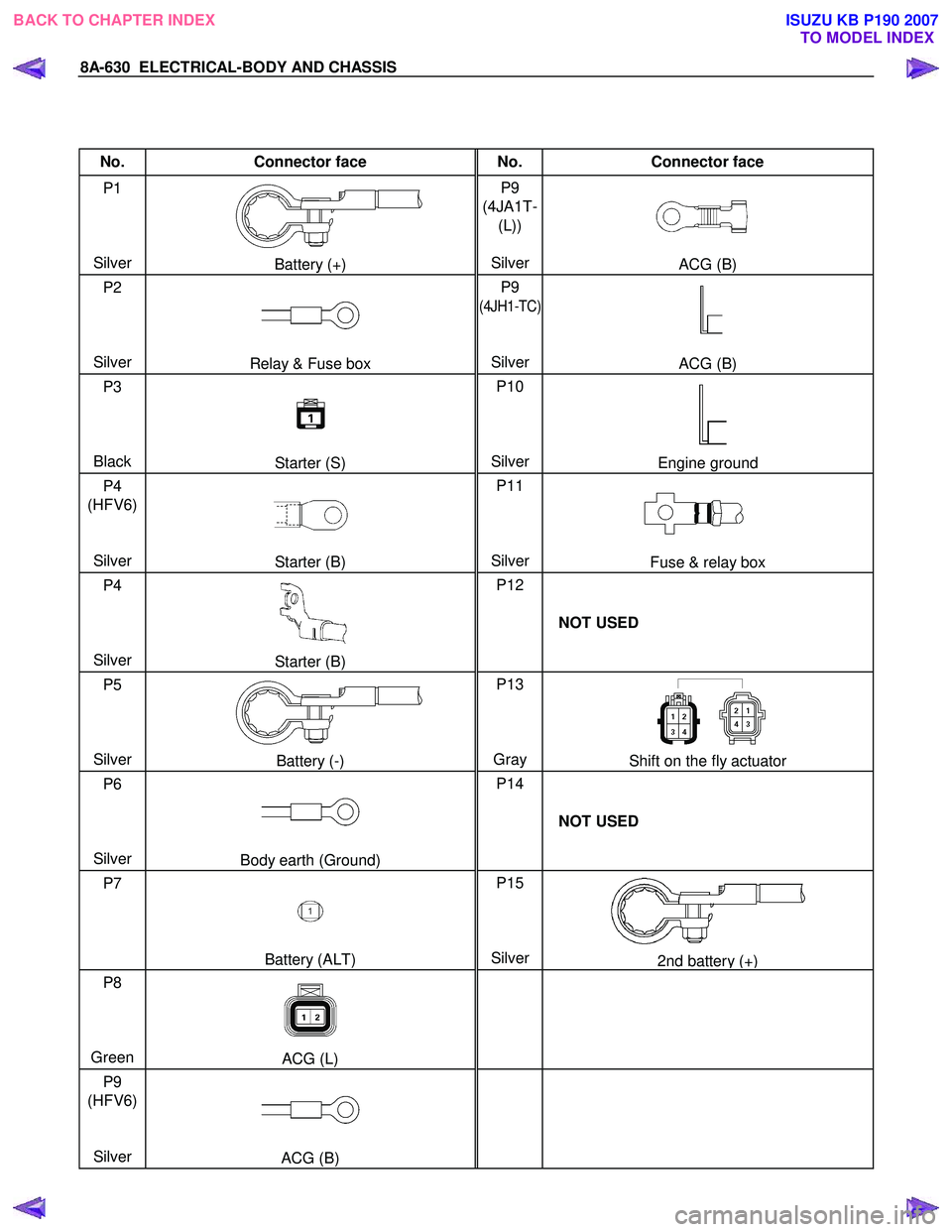
No. Connector face No. Connector face
P1
Silver
Battery (+) P9
(4JA1T- (L))
SilverACG (B)
P2
Silver
Relay & Fuse box P9
(4JH1-TC)
Silver
ACG (B)
P3
Black
Starter (S) P10
SilverEngine ground
P4
(HFV6)
Silver
Starter (B) P11
SilverFuse & relay box
P4
Silver
Starter (B) P12
NOT USED
P5
Silver
Battery (-) P13
Gray Shift on the fly actuator
P6
Silver
Body earth (Ground) P14
NOT USED
P7
Battery (ALT) P15
Silver2nd battery (+)
P8
Green
ACG (L)
P9
(HFV6)
Silver
ACG (B)
BACK TO CHAPTER INDEX
TO MODEL INDEXISUZU KB P190 2007
Page 5628 of 6020
ACCESSORIES 9-23
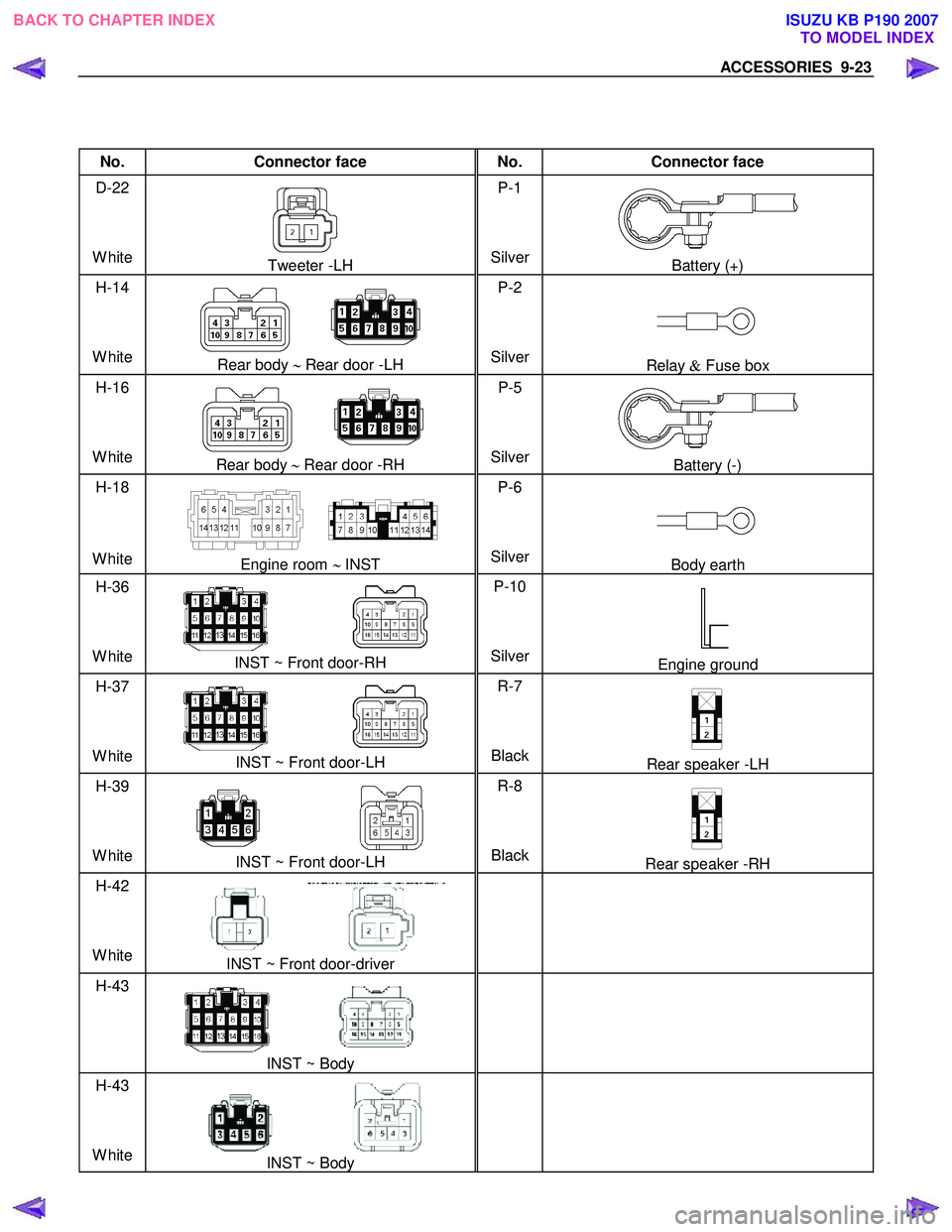
No. Connector face No. Connector face
D-22
White
Tweeter -LH P-1
SilverBattery (+)
H-14
White
Rear body ∼ Rear door -LH P-2
SilverRelay & Fuse box
H-16
White
Rear body ∼ Rear door -RH P-5
SilverBattery (-)
H-18
White
Engine room ∼ INST P-6
SilverBody earth
H-36
White
INST ~ Front door-RH P-10
SilverEngine ground
H-37
White
INST ~ Front door-LH R-7
BlackRear speaker -LH
H-39
White
INST ~ Front door-LH R-8
BlackRear speaker -RH
H-42
White
INST ~ Front door-driver
H-43
INST ~ Body
H-43
White
INST ~ Body
BACK TO CHAPTER INDEX TO MODEL INDEXISUZU KB P190 2007
Page 5656 of 6020
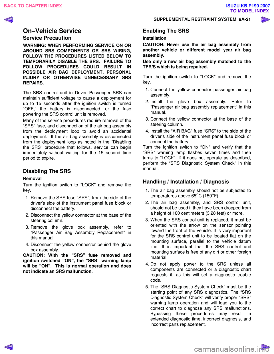
SUPPLEMENTAL RESTRAINT SYSTEM 9A-21
On–Vehicle Service
Service Precaution
WARNING: WHEN PERFORMING SERVICE ON OR
AROUND SRS COMPONENTS OR SRS WIRING,
FOLLOW THE PROCEDURES LISTED BELOW TO
TEMPORARILY DISABLE THE SRS. FAILURE TO
FOLLOW PROCEDURES COULD RESULT IN
POSSIBLE AIR BAG DEPLOYMENT, PERSONAL
INJURY OR OTHERWISE UNNECESSARY SRS
REPAIRS.
The SRS control unit in Driver–Passenger SRS can
maintain sufficient voltage to cause a deployment fo
r
up to 15 seconds after the ignition switch is turned
“OFF,” the battery is disconnected, or the fuse
powering the SRS control unit is removed.
Many of the service procedures require removal of the
“SRS” fuse, and disconnection of the air bag assembl
y
from the deployment loop to avoid an accidental
deployment. If the air bag assembly is disconnected
from the deployment loop as noted in the “Disabling
the SRS” procedure that follows, service can begin
immediately without waiting for the 15 second time
period to expire.
Disabling The SRS
Removal
Turn the ignition switch to “LOCK” and remove the
key.
1. Remove the SRS fuse “SRS”, from the side of the driver’s side of the instrument panel fuse block o
r
disconnect the battery.
2. Disconnect the yellow connector at the base of the steering column.
3. Remove the glove box assembly, refer to “Passenger Air Bag Assembly Replacement” in
this manual.
4. Disconnect the yellow connector behind the glove box assembly.
CAUTION: With the “SRS” fuse removed and
ignition switched “ON”, the “SRS” warning lamp
will be “ON”. This is normal operation and does
not indicate an SRS malfunction.
Enabling The SRS
Installation
CAUTION: Never use the air bag assembly from
another vehicle or different model year air bag
assembly.
Use only a new air bag assembly matched to the
TFR/S which is being repaired.
Turn the ignition switch to “LOCK” and remove the
key.
1. Connect the yellow connector passenger air bag assembly.
2. Install the glove box assembly. Refer to “Passenger air bag assembly replacement” in this
manual.
3. Connect the yellow connector at the base of the steering column.
4. Install the “AIR BAG” fuse “SRS” to the side of the driver’s side of the instrument panel fuse block o
r
connect the battery.
Turn the ignition switch to “ON” and verify that the
“SRS” warning lamp flashes seven times and then
turns to “LOCK”. If it does not operate as described,
perform the “SRS Diagnostic System Check” in this
manual.
Handling / Installation / Diagnosis
1. The air bag assembly should not be subjected to temperatures above 65
°C (150°F).
2. The air bag assembly, and SRS control unit, should not be used if they have been dropped from
a height of 100 centimeters (3.28 feet) or more.
3. W hen the SRS control unit is replaced, it must be oriented with the arrow on the sensor pointing
toward the front of the vehicle. It is very important
for the SRS control unit to be located flat on the
mounting surface, parallel to the vehicle datum
line. It is important that the SRS control unit
mounting surface is free of any dirt or other foreign
material.
4. Do not apply power to the SRS unless all components are connected or a diagnostic chart
requests it, as this will set a diagnostic trouble
code.
5. The “SRS Diagnostic System Check” must be the starting point of any SRS diagnostics. The “SRS
Diagnostic System Check” will verify proper “SRS”
warning lamp operation and will lead you to the
correct chart to diagnose any SRS malfunctions.
Bypassing these procedures may result in
extended diagnostic time, incorrect diagnosis, and
incorrect parts replacement.
BACK TO CHAPTER INDEX TO MODEL INDEXISUZU KB P190 2007
Page 5667 of 6020
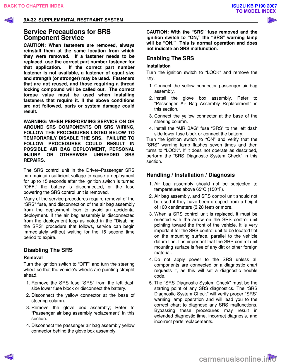
9A-32 SUPPLEMENTAL RESTRAINT SYSTEM
Service Precautions for SRS
Component Service
CAUTION: When fasteners are removed, always
reinstall them at the same location from which
they were removed. If a fastener needs to be
replaced, use the correct part number fastener fo
r
that application. If the correct part number
fastener is not available, a fastener of equal size
and strength (or stronger) may be used. Fasteners
that are not reused, and those requiring a thread
locking compound will be called out. The correct
torque value must be used when installing
fasteners that require it. If the above conditions
are not followed, parts or system damage could
result.
WARNING: WHEN PERFORMING SERVICE ON OR
AROUND SRS COMPONENTS OR SRS WIRING,
FOLLOW THE PROCEDURES LISTED BELOW TO
TEMPORARILY DISABLE THE SRS. FAILURE TO
FOLLOW PROCEDURES COULD RESULT IN
POSSIBLE AIR BAG DEPLOYMENT, PERSONAL
INJURY OR OTHERWISE UNNEEDED SRS
REPAIRS.
The SRS control unit in the Driver–Passenger SRS
can maintain sufficient voltage to cause a deployment
for up to 15 seconds after the ignition switch is turned
“OFF,” the battery is disconnected, or the fuse
powering the SRS control unit is removed.
Many of the service procedures require removal of the
“SRS” fuse, and disconnection of the air bag assembl
y
from the deployment loop to avoid an accidental
deployment. If the air bag assembly is disconnected
from the deployment loop as noted in the “Disabling
the SRS” procedure that follows, service can begin
immediately without waiting for the 15 second time
period to expire.
Disabling The SRS
Removal
Turn the ignition switch to “OFF” and turn the steering
wheel so that the vehicle's wheels are pointing straight
ahead.
1. Remove the SRS fuse “SRS” from the left dash side lower fuse block or disconnect the battery.
2. Disconnect the yellow connector at the base o
f
steering column.
3. Remove the glove box assembly; Refer to “Passenger air bag assembly replacement” in this
section.
4. Disconnect the passenger air bag assembly yello
w
connector behind the glove box assembly.
CAUTION: With the “SRS” fuse removed and the
ignition switch to “ON,” the “SRS” warning lamp
will be “ON.” This is normal operation and does
not indicate an SRS malfunction.
Enabling The SRS
Installation
Turn the ignition switch to “LOCK” and remove the
key.
1. Connect the yellow connector passenger air bag assembly.
2. Install the glove box assembly. Refer to “Passenger Air Bag Assembly Replacement” in
this section.
3. Connect the yellow connector at the base of the steering column.
4. Install the “AIR BAG” fuse “SRS” to the left dash side lower fuse block or connect the battery.
Turn the ignition switch to “ON” and verify that the
“SRS” warning lamp flashes seven times and then
turns to “LOCK”. If it does not operate as described,
perform the “SRS Diagnostic System Check” in this
section.
Handling / Installation / Diagnosis
1. Air bag assembly should not be subjected to
temperatures above 65 °C (150 °F).
2.
Air bag assembly, and SRS control unit should not
be used if they have been dropped from a height
of 100 centimeters (3.28 feet) or more.
3. W hen a SRS control unit is replaced, it must be oriented with the arrow on the SRS control unit
pointing toward the front of the vehicle. It is ver
y
important for the SRS control unit to be located flat
on the mounting surface, parallel to the vehicle
datum line. It is important that the SRS control unit
mounting surface is free of any dirt or other foreign
material.
4. Do not apply power to the SRS unless all components are connected or a diagnostic chart
requests it, as this will set a diagnostic trouble
code.
5. The “SRS Diagnostic System Check” must be the starting point of any SRS diagnostics. The “SRS
Diagnostic System Check” will verify proper “SRS”
warning lamp operation and will lead you to the
correct chart to diagnose any SRS malfunctions.
Bypassing these procedures may result in
extended diagnostic time, incorrect diagnosis, and
incorrect parts replacements.
BACK TO CHAPTER INDEX TO MODEL INDEXISUZU KB P190 2007
Page 5697 of 6020
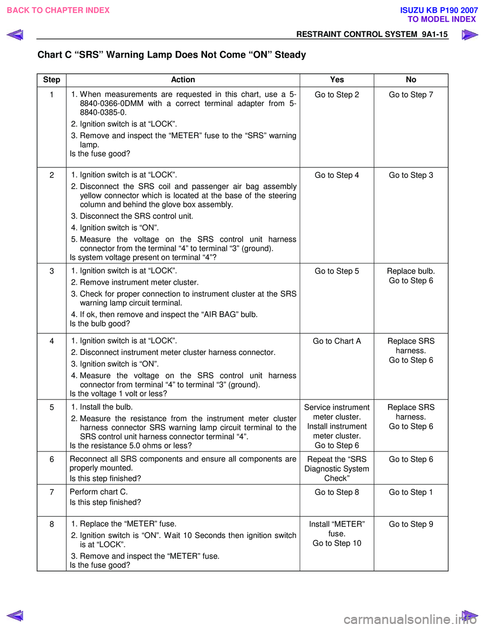
RESTRAINT CONTROL SYSTEM 9A1-15
Chart C “SRS” Warning Lamp Does Not Come “ON” Steady
Step Action Yes No
1
1. W hen measurements are requested in this chart, use a 5-
8840-0366-0DMM with a correct terminal adapter from 5-
8840-0385-0.
2. Ignition switch is at “LOCK”.
3. Remove and inspect the “METER” fuse to the “SRS” warning lamp.
Is the fuse good? Go to Step 2 Go to Step 7
2
1. Ignition switch is at “LOCK”.
2. Disconnect the SRS coil and passenger air bag assembly
yellow connector which is located at the base of the steering
column and behind the glove box assembly.
3. Disconnect the SRS control unit.
4. Ignition switch is “ON”.
5. Measure the voltage on the SRS control unit harness connector from the terminal “4” to terminal “3” (ground).
Is system voltage present on terminal “4”? Go to Step 4 Go to Step 3
3
1. Ignition switch is at “LOCK”.
2. Remove instrument meter cluster.
3. Check for proper connection to instrument cluster at the SRS warning lamp circuit terminal.
4. If ok, then remove and inspect the “AIR BAG” bulb.
Is the bulb good? Go to Step 5 Replace bulb.
Go to Step 6
4
1. Ignition switch is at “LOCK”.
2. Disconnect instrument meter cluster harness connector.
3. Ignition switch is “ON”.
4. Measure the voltage on the SRS control unit harness
connector from terminal “4” to terminal “3” (ground).
Is the voltage 1 volt or less? Go to Chart A Replace SRS
harness.
Go to Step 6
5
1. Install the bulb.
2. Measure the resistance from the instrument meter cluster
harness connector SRS warning lamp circuit terminal to the
SRS control unit harness connector terminal “4”.
Is the resistance 5.0 ohms or less? Service instrument
meter cluster.
Install instrument meter cluster. Go to Step 6 Replace SRS
harness.
Go to Step 6
6 Reconnect all SRS components and ensure all components are
properly mounted.
Is this step finished? Repeat the “SRS
Diagnostic System Check” Go to Step 6
7
Perform chart C.
Is this step finished? Go to Step 8 Go to Step 1
8
1. Replace the “METER” fuse.
2. Ignition switch is “ON”. W ait 10 Seconds then ignition switch
is at “LOCK”.
3. Remove and inspect the “METER” fuse.
Is the fuse good? Install “METER”
fuse.
Go to Step 10 Go to Step 9
BACK TO CHAPTER INDEX
TO MODEL INDEX
ISUZU KB P190 2007
Page 5698 of 6020
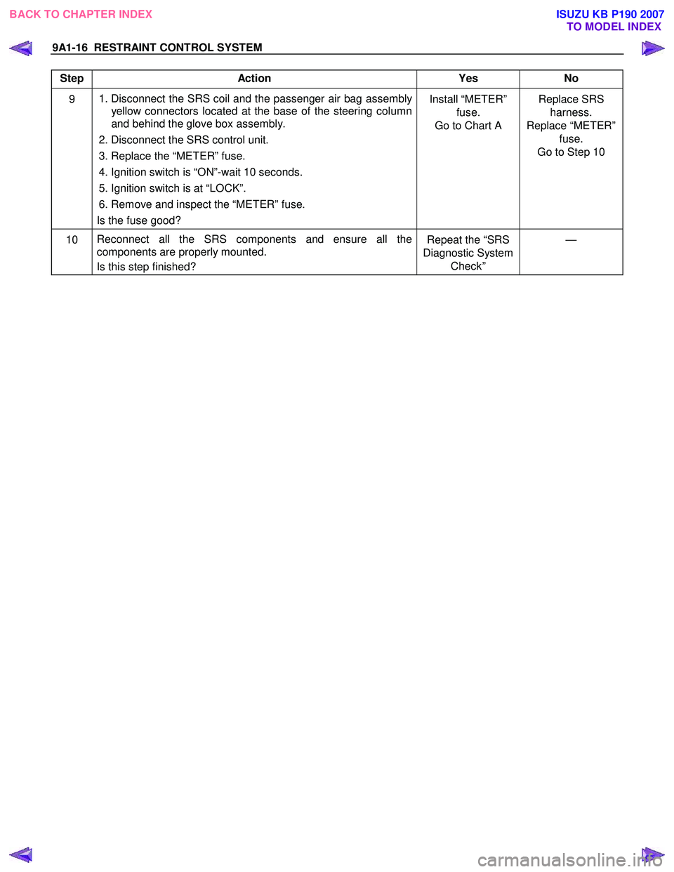
9A1-16 RESTRAINT CONTROL SYSTEM
Step Action Yes No
9
1. Disconnect the SRS coil and the passenger air bag assembly
yellow connectors located at the base of the steering column
and behind the glove box assembly.
2. Disconnect the SRS control unit.
3. Replace the “METER” fuse.
4. Ignition switch is “ON”-wait 10 seconds.
5. Ignition switch is at “LOCK”.
6. Remove and inspect the “METER” fuse.
Is the fuse good? Install “METER”
fuse.
Go to Chart A Replace SRS
harness.
Replace “METER” fuse.
Go to Step 10
10 Reconnect all the SRS components and ensure all the
components are properly mounted.
Is this step finished? Repeat the “SRS
Diagnostic System Check” —
BACK TO CHAPTER INDEX
TO MODEL INDEX
ISUZU KB P190 2007