Page 2200 of 6020
6E–30 ENGINE DRIVEABILITY AND EMISSIONS
RELAY AND FUSE
RELAY AND FUSE BOX LOCATION (LHD & RHD)
LHDRHD
BACK TO CHAPTER INDEX
TO MODEL INDEX
ISUZU KB P190 2007
Page 2201 of 6020
ENGINE DRIVEABILITY AND EMISSIONS 6E–31
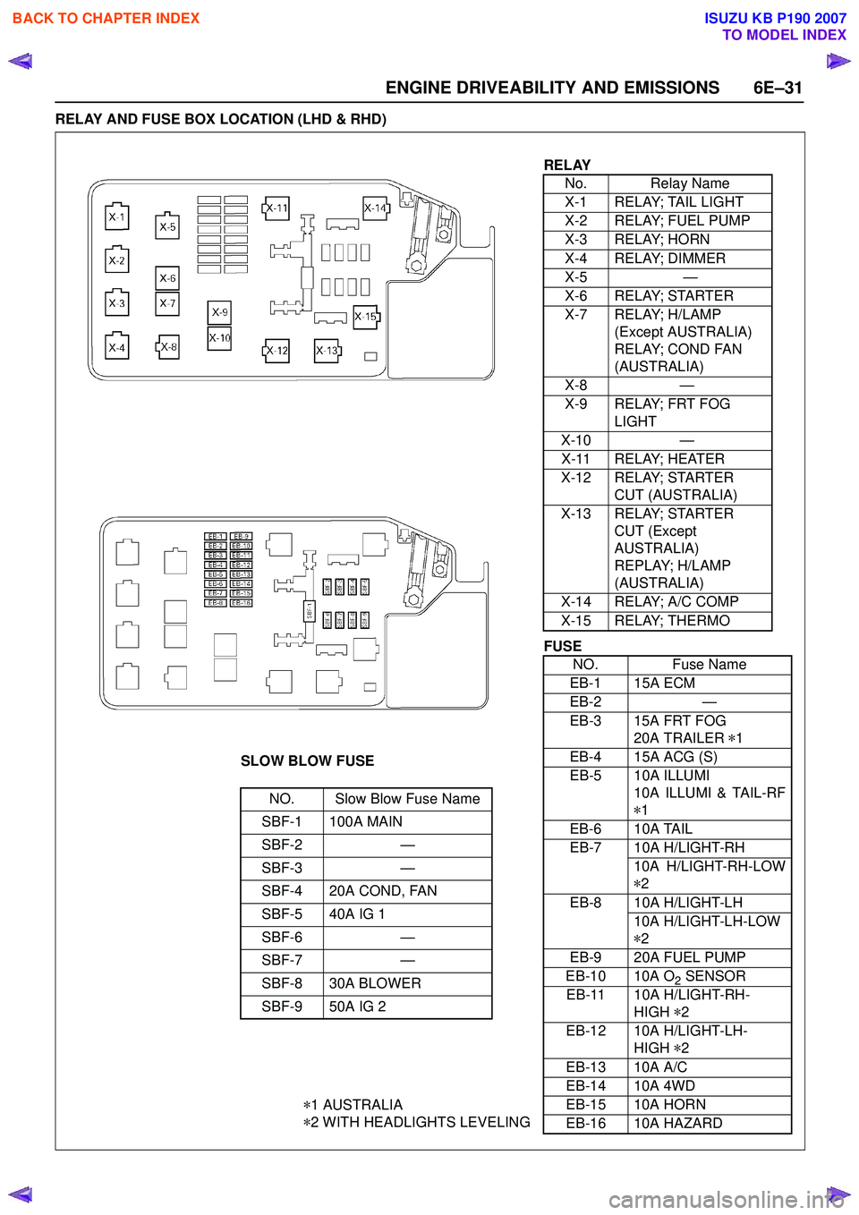
RELAY AND FUSE BOX LOCATION (LHD & RHD)
RELAYNo. Relay Name
X-1 RELAY; TAIL LIGHT
X-2 RELAY; FUEL PUMP
X-3 RELAY; HORN
X-4 RELAY; DIMMER
X-5 —
X-6 RELAY; STARTER
X-7 RELAY; H/LAMP (Except AUSTRALIA)
RELAY; COND FAN
(AUSTRALIA)
X-8 —
X-9 RELAY; FRT FOG LIGHT
X-10 —
X-11 RELAY; HEATER
X-12 RELAY; STARTER CUT (AUSTRALIA)
X-13 RELAY; STARTER CUT (Except
AUSTRALIA)
REPLAY; H/LAMP
(AUSTRALIA)
X-14 RELAY; A/C COMP
X-15 RELAY; THERMO
SLOW BLOW FUSE
NO. Slow Blow Fuse Name
SBF-1 100A MAIN
SBF-2 —
SBF-3 —
SBF-4 20A COND, FAN
SBF-5 40A IG 1
SBF-6 —
SBF-7 —
SBF-8 30A BLOWER
SBF-9 50A IG 2
* 1 AUSTRALIA
* 2 WITH HEADLIGHTS LEVELING
FUSE
NO. Fuse Name
EB-1 15A ECM
EB-2 —
EB-3 15A FRT FOG 20A TRAILER *1
EB-4 15A ACG (S)
EB-5 10A ILLUMI 10A ILLUMI & TAIL-RF
* 1
EB-6 10A TAIL
EB-7 10A H/LIGHT-RH 10A H/LIGHT-RH-LOW
* 2
EB-8 10A H/LIGHT-LH 10A H/LIGHT-LH-LOW
* 2
EB-9 20A FUEL PUMP
EB-10 10A O
2 SENSOR
EB-11 10A H/LIGHT-RH- HIGH *2
EB-12 10A H/LIGHT-LH- HIGH *2
EB-13 10A A/C
EB-14 10A 4WD
EB-15 10A HORN
EB-16 10A HAZARD
BACK TO CHAPTER INDEX
TO MODEL INDEX
ISUZU KB P190 2007
Page 2202 of 6020
6E–32 ENGINE DRIVEABILITY AND EMISSIONS
FUSE AND RELAY LOCATION (LHD & RHD)
FUSE
SLOW BLOW FUSE
RELAY No. Capacity Indication on label No. Capacity Indication on label
1— — 1 215A CIGER/ACC
SOCKET
2 10A ABS/4WD 13 15A AUDIO (+B)
3 10A TRAILER 14 20A DOOR LOCK
4 15A BACK UP 15 10A METER (+B)
5 15A METER16 10A ROOM
6 10A TURN17 10A ANTI THEFT
7 15A ELEC.IG 18 15ASTOP
815A ENGINE 19 — —
9 20A FRT WIPER 20 10A STARTER
10 15A EGR (RHD)
IG.COIL (LHD) 21 10A
SRS
11 10A AUDIO
No. Capacity Indication on label 22 20A RR DEF
23 30A POWER WINDOW
Connector No. B-7B-8B-40
C24SE REAR DEFOGGER POWER WINDOW (NO RELAY)
FUSE BOX
BACK TO CHAPTER INDEX
TO MODEL INDEX
ISUZU KB P190 2007
Page 2232 of 6020
6E–62 ENGINE DRIVEABILITY AND EMISSIONS
Diagnostic Thought Process
As you follow a diagnostic plan, every box on the
Strategy Based Diagnostics chart requires you to use
the diagnostic thought process. This method of thinking
optimizes your diagnosis in the following ways:
• Improves your understanding and definition of the customer complaint
• Saves time by avoiding testing and/or replacing good parts
• Allows you to look at the problem from different perspectives
• Guides you to determine what level of understanding about system operation is needed:
– Owner’s manual level
– Service manual level
– In-depth (engineering) level – Owner’s manual level
– Service manual level
– In-depth (engineering) level
1. Verify the Complaint
What you should do
To verify the customer complaint, you need to know the
correct (normal) operating behavior of the system and
verify that the customer complaint is a valid failure of the
system.
The following information will help you verify the
complaint:
• WHAT the vehicle model/options are
• WHAT aftermarket and dealer-installed accessories exist
• WHAT related system(s) operate properly
• WHEN the problem occurs
• WHERE the problem occurs
• HOW the problem occurs
• HOW LONG the condition has existed (and if the system ever worked correctly)
• HOW OFTEN the problem occurs
• Whether the severity of the problem has increased, decreased or stayed the same
What resources you should use
Whenever possible, you should use the following
resources to assist you in verifying the complaint:
• Service manual Theory or Circuit Description sections
• Service manual “System Performance Check”
• Owner manual operational description
• Technician experience
• Identical vehicle for comparison • Circuit testing tools
• Vehicle road tests
• Complaint check sheet
• Contact with the customer
2. Perform Preliminary Checks
NOTE: An estimated 10 percent of successful vehicle
repairs are diagnosed with this step!
What you should do
You perform preliminary checks for several reasons:
• To detect if the cause of the complaint is VISUALLY OBVIOUS
• To identify parts of the system that work correctly
• To accumulate enough data to correctly and accurately search for a ISUZU Service Bulletin on
ISUZU Web site.
The initial checks may vary depending on the
complexity of the system and may include the following
actions:
• Operate the suspect system
• Make a visual inspection of harness routing and accessible/visible power and ground circuits
• Check for blown fuses
• Make a visual inspection for separated connectors
• Make a visual inspection of connectors (includes checking terminals for damage and tightness)
• Check for any DTCs stored by the on-board computers
• Sense unusual noises, smells, vibrations or movements
• Investigate the vehicle service history (call other dealerships, if appropriate)
What resources you should use
Whenever appropriate, you should use the following
resources for assistance in performing preliminary
checks:
• Tech II or other technical equipment for viewing DTCs
• Service manual information: – Component locations
– Harness routing
– Wiring schematics
– Procedures for viewing DTCs
• Dealership service history file
• Vehicle road test
• Identical vehicle or system for comparison
BACK TO CHAPTER INDEX
TO MODEL INDEX
ISUZU KB P190 2007
Page 2274 of 6020
6E–104 ENGINE DRIVEABILITY AND EMISSIONS
Fuel Pressure Relief Procedure
1. Remove the fuel cap.
2. Remove the fuel pump relay from the underhood relay center.
3. Start the engine and alow it to stall.
4. Crank the engine for an additional 3 seconds.
Fuel Pressure Gauge Installation
1. Remove the fuel pressure fitting cap.
2. Install fuel pressure gauge 5-8840-0378-0 to the fuel feed line located in front of and above the right
side valve cover.
3. Reinstall the fuel pump relay.
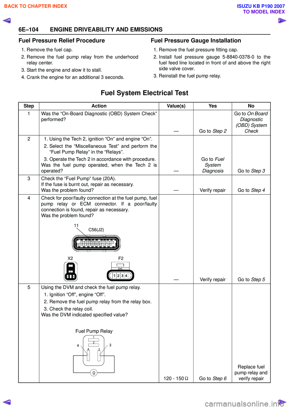
Fuel System Electrical Test
Step Action Value(s) Yes No
1 Was the “On-Board Diagnostic (OBD) System Check” performed?
—Go to Step 2Go to
On Board
Diagnostic
(OBD) System Check
2 1. Using the Tech 2, ignition “On” and engine “On”. 2. Select the “Miscellaneous Test” and perform the“Fuel Pump Relay” in the “Relays”.
3. Operate the Tech 2 in accordance with procedure.
Was the fuel pump operated, when the Tech 2 is
operated? —Go to
Fuel
System
Diagnosis Go to Step 3
3 Check the “Fuel Pump” fuse (20A). If the fuse is burnt out, repair as necessary.
Was the problem found? — Verify repair Go to Step 4
4 Check for poor/faulty connection at the fuel pump, fuel pump relay or ECM connector. If a poor/faulty
connection is found, repair as necessary.
Was the problem found?
— Verify repair Go to Step 5
5 Using the DVM and check the fuel pump relay. 1. Ignition “Off”, engine “Off”.
2. Remove the fuel pump relay from the relay box.
3. Check the relay coil.
Was the DVM indicated specified value?
120 - 150ΩGo to Step 6 Replace fuel
pump relay and verify repair
11C56(J2)
F2
X2
Fuel Pump Relay
3
4 2
1
Ω
34
BACK TO CHAPTER INDEX
TO MODEL INDEX
ISUZU KB P190 2007
Page 2275 of 6020
ENGINE DRIVEABILITY AND EMISSIONS 6E–105
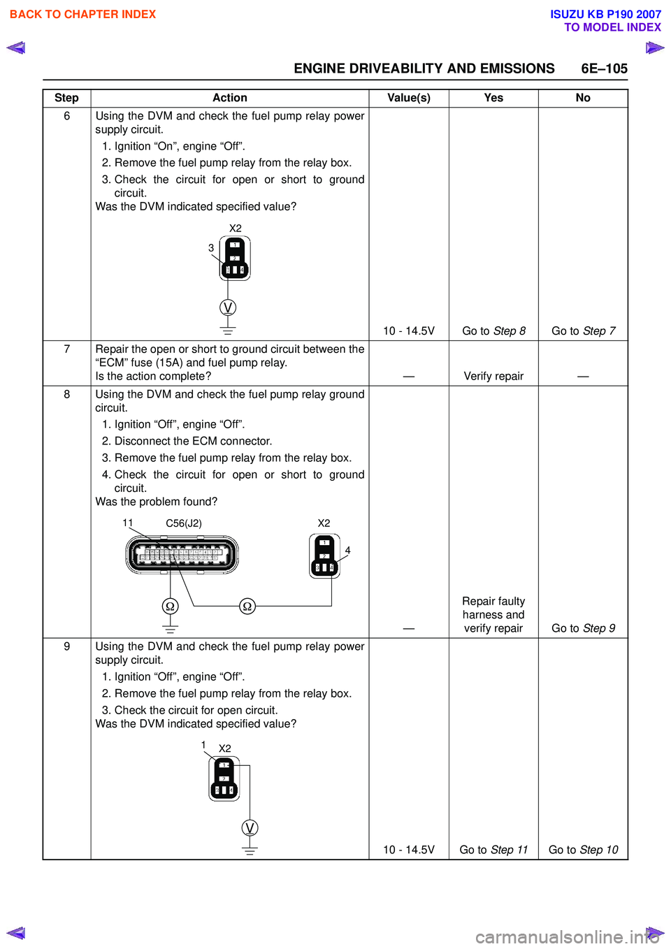
6 Using the DVM and check the fuel pump relay powersupply circuit.
1. Ignition “On”, engine “Off”.
2. Remove the fuel pump relay from the relay box.
3. Check the circuit for open or short to ground circuit.
Was the DVM indicated specified value?
10 - 14.5V Go to Step 8Go to Step 7
7 Repair the open or short to ground circuit between the “ECM” fuse (15A) and fuel pump relay.
Is the action complete? — Verify repair —
8 Using the DVM and check the fuel pump relay ground circuit.
1. Ignition “Off”, engine “Off”.
2. Disconnect the ECM connector.
3. Remove the fuel pump relay from the relay box.
4. Check the circuit for open or short to ground circuit.
Was the problem found?
—Repair faulty
harness and verify repair Go to Step 9
9 Using the DVM and check the fuel pump relay power supply circuit.
1. Ignition “Off”, engine “Off”.
2. Remove the fuel pump relay from the relay box.
3. Check the circuit for open circuit.
Was the DVM indicated specified value?
10 - 14.5V Go to Step 11Go to Step 10
Step
Action Value(s) Yes No
V
3
X2
4
11C56(J2)X2
V
1X2
BACK TO CHAPTER INDEX
TO MODEL INDEX
ISUZU KB P190 2007
Page 2335 of 6020
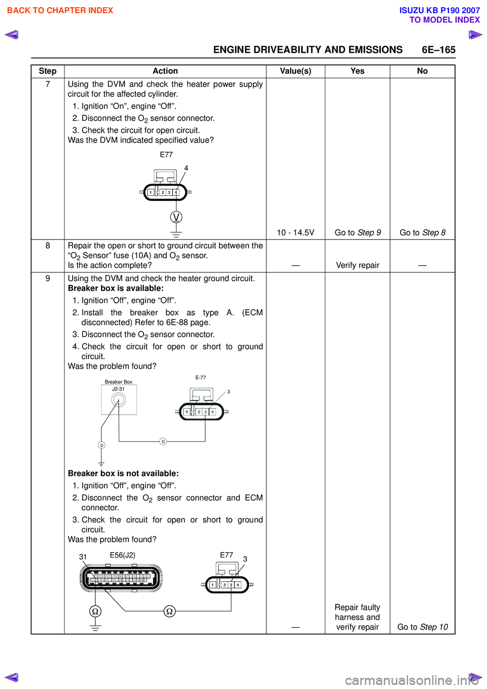
ENGINE DRIVEABILITY AND EMISSIONS 6E–165
7 Using the DVM and check the heater power supplycircuit for the affected cylinder.
1. Ignition “On”, engine “Off”.
2. Disconnect the O
2 sensor connector.
3. Check the circuit for open circuit.
Was the DVM indicated specified value?
10 - 14.5V Go to Step 9Go to Step 8
8 Repair the open or short to ground circuit between the “O
2 Sensor” fuse (10A) and O2 sensor.
Is the action complete? — Verify repair —
9 Using the DVM and check the heater ground circuit. Breaker box is available:
1. Ignition “Off”, engine “Off”.
2. Install the breaker box as type A. (ECM disconnected) Refer to 6E-88 page.
3. Disconnect the O
2 sensor connector.
4. Check the circuit for open or short to ground circuit.
Was the problem found?
Breaker box is not available:
1. Ignition “Off”, engine “Off”.
2. Disconnect the O
2 sensor connector and ECM
connector.
3. Check the circuit for open or short to ground circuit.
Was the problem found?
—Repair faulty
harness and verify repair Go to Step 10
Step
Action Value(s) Yes No
4
V
E77
J2-31Breaker BoxE-77
3
ΩΩ
331E56(J2)E77
BACK TO CHAPTER INDEX
TO MODEL INDEX
ISUZU KB P190 2007
Page 2363 of 6020
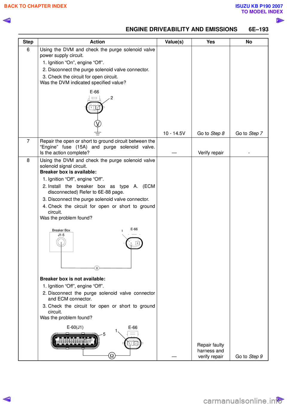
ENGINE DRIVEABILITY AND EMISSIONS 6E–193
6 Using the DVM and check the purge solenoid valvepower supply circuit.
1. Ignition “On”, engine “Off”.
2. Disconnect the purge solenoid valve connector.
3. Check the circuit for open circuit.
Was the DVM indicated specified value?
10 - 14.5V Go to Step 8Go to Step 7
7 Repair the open or short to ground circuit between the “Engine” fuse (15A) and purge solenoid valve.
Is the action complete? — Verify repair -
8 Using the DVM and check the purge solenoid valve solenoid signal circuit.
Breaker box is available:
1. Ignition “Off”, engine “Off”.
2. Install the breaker box as type A. (ECM disconnected) Refer to 6E-88 page.
3. Disconnect the purge solenoid valve connector.
4. Check the circuit for open or short to ground circuit.
Was the problem found?
Breaker box is not available:
1. Ignition “Off”, engine “Off”.
2. Disconnect the purge solenoid valve connector and ECM connector.
3. Check the circuit for open or short to ground circuit.
Was the problem found?
—Repair faulty
harness and verify repair Go to Step 9
Step Action Value(s) Yes No
V
E-66
2
J1-5Breaker BoxE-66
Ω
1
E-66
E-60(J1)
51
BACK TO CHAPTER INDEX
TO MODEL INDEX
ISUZU KB P190 2007