2007 ISUZU KB P190 DTC CHECK
[x] Cancel search: DTC CHECKPage 3988 of 6020
7A2-22 TRANSMISSION CONTROL SYSTEM (AW30–40LE)
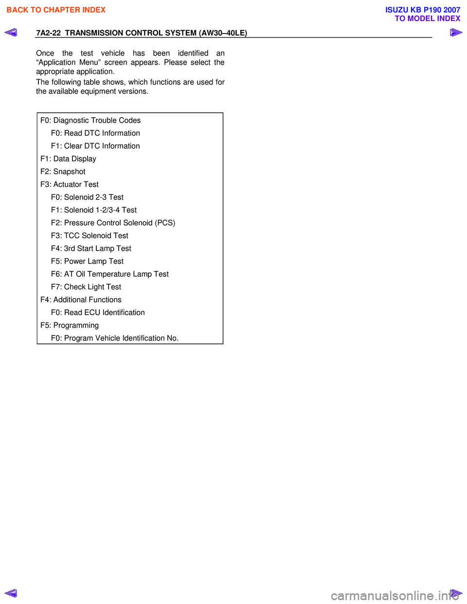
Once the test vehicle has been identified an
“Application Menu” screen appears. Please select the
appropriate application.
The following table shows, which functions are used fo
r
the available equipment versions.
F0: Diagnostic Trouble Codes
F0: Read DTC Information
F1: Clear DTC Information
F1: Data Display
F2: Snapshot
F3: Actuator Test
F0: Solenoid 2-3 Test
F1: Solenoid 1-2/3-4 Test
F2: Pressure Control Solenoid (PCS)
F3: TCC Solenoid Test
F4: 3rd Start Lamp Test
F5: Power Lamp Test
F6: AT Oil Temperature Lamp Test
F7: Check Light Test
F4: Additional Functions
F0: Read ECU Identification
F5: Programming
F0: Program Vehicle Identification No.
BACK TO CHAPTER INDEX
TO MODEL INDEX
ISUZU KB P190 2007
Page 3989 of 6020
TRANSMISSION CONTROL SYSTEM (AW30–40LE) 7A2-23
Diagnostic Trouble Codes
The purpose of the “Diagnostic Trouble Codes” mode is
to display stored TCM trouble codes.
W hen “Diagnostic Trouble Codes” is selected an
“Application Menu” screen appears.
Read DTC Information
W hen “Read DTC Information” is selected, an
“Application Menu” appears with a list of DTC
information function keys addressing DTC specifics and
their origins.
Function key selections may vary for particular vehicle
and/or system.
Requested emission-related DTCs
Clear DTC Information
The purpose of the “Clear DTC Information” mode is to
command the clearing of stored TCM trouble codes.
W hen “Clear DTC Information” is selected, a “Clea
r
DTC Information”, warning screen appears. This screen
informs you that by cleaning DTC's, “all stored DTC
information in controller will be erased”.
Do you want to clear DTC's (Yes/No).
Press either the Yes or No key when answering.
After clearing codes, confirm system operation by test-
driving the vehicle.
Allow the vehicle to shift through all four forward gears
in a manner which attempts to repeat the failure
condition.
NOTE: W hen the trouble has not been repaired and
the trouble code cannot be erased, check the vehicle
again.
Data Display
The purpose of the “Data Display” mode is to
continuously monitor data parameters.
The current actual values of all important sensors and
signals in the system are displayed through F1 mode.
W hen “Data Display” is selected an “Application Menu”
appears. “Transmission Data Display”.
See “Transmission Data” on next page.
Snapshot
W hen “Snapshot” is selected an “Application Menu”
appears.
W hen “Transmission Snapshot” application is selected
from the “Application Menu”, a “Snapshot Menu”
appears, displaying several options. “Snapshot” options
may vary from one system to another.
“Snapshot” allows a recording of all vehicle parameters.
There parameters may then be replayed at a future
point in time.
This action allows you to focus on making the condition
occur, rather than trying to view all of the data in
anticipation of the fault. The snapshot will collect
parameter information around a trigger point that you
select.
W hen a snapshot is taken, it is recorded onto the
PCMCIA memory card. W hen the Tech 2 is powered
down. Snapshots are not lost.
Actuator Test
The purpose of “Actuator Test” mode is to check fo
r
correct operation of electronic system actuators.
Solenoid 2-3 Test, Solenoid 1-2/3-4 and Test TCC
Solenoid Test
You can operate the solenoids by pressing the “ON”
and “OFF” buttons.
Preconditions: P–N position, no vehicle speed, no
engine speed
Pressure Control Solenoid (PCS)
You can set desired PCS Current using the “ON” and
“OFF” button. The PCS Data informs about PCS
Current, Pressure and Duty Cycle.
Preconditions: P–N position, no engine speed, no
vehicle speed
3rd Start Lamp Test, Power Lamp Test, AT Oil
Temperature Lamp Test and Check Light Test
You can operate the lamps by pressing the “ON” and
“OFF” buttons.
Preconditions: none
NOTE: Freeze Frame
Freeze Frame is an element of the Diagnostic
Management System which stores various vehicle
information at the moment an emission-related fault
is stored in memory and when the Check Trans
Lamp is commanded on. These data can help to
identity the cause of a fault. Refer to Storing An
d
Erasing Freeze Frame Data for more detaile
d
information.
BACK TO CHAPTER INDEX
TO MODEL INDEX
ISUZU KB P190 2007
Page 3996 of 6020
7A2-30 TRANSMISSION CONTROL SYSTEM (AW30–40LE)
Service Programming System (SPS)
The procedure to program the control unit by using the
Service Programming System (SPS) software
contained in TIS2000 is explained below.
NOTE: • Should Tech2 display “SPS Procedure was not
successful”, engine will not start, but no DTCs are
present, low battery voltage or poor electrical
connections should be the primary suspects.
Perform the SPS procedure again after rectifying
the fault/s.
IMPORTANT:
Perform the following checks before attempting to
program the control unit:
•
••
•
The Tech2 PCMCIA card is programmed with
the latest software release.
•
••
•
The latest release of TIS2000 is loaded on the
PC.
•
••
•
The vehicle battery is fully charged.
•
••
•
The control unit to be programmed is
connected to the vehicle.
1. Preparations of TIS 2000
1. Connect Tech 2 to P/C.
2. Check to see if Hardware Key is plugged into Port.
3. Activate TIS 2000 by P/C.
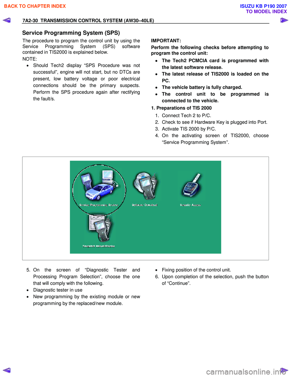
4. On the activating screen of TIS2000, choose
“Service Programming System”.
5. On the screen of “Diagnostic Tester and
Processing Program Selection”, choose the one
that will comply with the following.
• Diagnostic tester in use
• New programming by the existing module or ne
w
programming by the replaced/new module.
• Fixing position of the control unit.
6. Upon completion of the selection, push the button
of “Continue”.
BACK TO CHAPTER INDEX
TO MODEL INDEX
ISUZU KB P190 2007
Page 4001 of 6020
TRANSMISSION CONTROL SYSTEM (AW30–40LE) 7A2-35
Clear DTC
NOTE: If you clear the DTC (Diagnostic Trouble
Codes) you will not be able to read any codes recorded
during the last occurrence.
NOTE: To use the DTC again to identify a problem, you
will need to reproduce the fault or the problem. This
may require a new test drive or just turning the ignition
on (this depends on the nature of the fault).
1. IF you have a Tech 2:
1. Connect the Tech 2 and perform the Tech 2
Operating.
2. Push “F1: Clear DTC Information” in the
Application Menu and answer “Yes” to the
question “Do you want to clear DTC's?”
a. W hen a malfunction still exists and the Tech 2 displays “AW 30-40 CODES NOT
CLEARED”. This means that the problem is
still there or that the recovery was not done.
Please go to DTC Check.
b. W hen a malfunction has been repaired and the recovery is done the Tech 2 displays
“AW 30-40LE CODES CLEARED”.
2. W hen you have no Tech 2, the storaged trouble
codes can be cleared by shorting the terminals
No.11 and No.4 or 5 (ground) of data link connecto
r
with a lead wire for 1 ∼ 6 seconds.
DTC Check
1. Diagnostic Trouble Codes (DTC) have been
identified by Tech 2.
2. You have written the list of the DTCs. The order o
f
the malfunctions has no meanings for this TCM.
Usually only one or two malfunctions should be set
for a given problem.
3. Check directly the DTCs you identified. The DTCs
are sorted by number. Refer to Diagnostic Trouble
Code (DTC) Identification in this section.
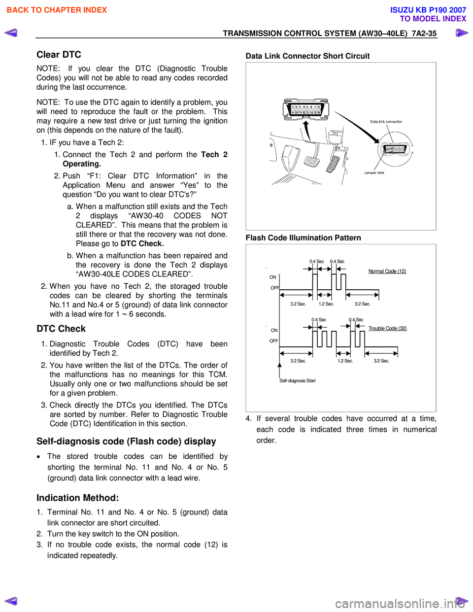
Self-diagnosis code (Flash code) display
• The stored trouble codes can be identified by
shorting the terminal No. 11 and No. 4 or No. 5
(ground) data link connector with a lead wire.
Indication Method:
1. Terminal No. 11 and No. 4 or No. 5 (ground) data
link connector are short circuited.
2. Turn the key switch to the ON position.
3. If no trouble code exists, the normal code (12) is
indicated repeatedly.
Data Link Connector Short Circuit
Flash Code Illumination Pattern
0.4 Sec 0.4 Sec
.
ON
OFF
3.2 Sec.
1.2 Sec.
3.2 Sec.
0.4 Sec 0.4 Sec
.
ON
OFF
3.2 Sec. 1.2 Sec. 3.2 Sec.
Self-diagnosis Start
Normal Code (12)
Trouble Code (32)
4. If several trouble codes have occurred at a time,
each code is indicated three times in numerical
order.
BACK TO CHAPTER INDEX
TO MODEL INDEX
ISUZU KB P190 2007
Page 4004 of 6020
7A2-38 TRANSMISSION CONTROL SYSTEM (AW30–40LE)
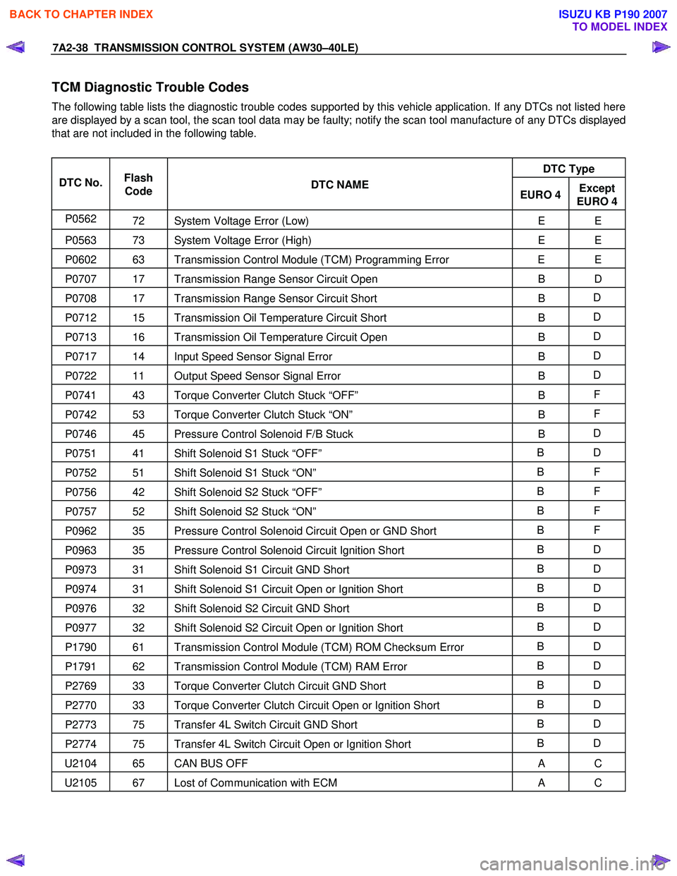
TCM Diagnostic Trouble Codes
The following table lists the diagnostic trouble codes supported by this vehicle application. If any DTCs not listed here
are displayed by a scan tool, the scan tool data may be faulty; notify the scan tool manufacture of any DTCs displayed
that are not included in the following table.
DTC Type
DTC No. Flash
Code DTC NAME
EURO 4Except
EURO 4
P0562 72 System Voltage Error (Low) E E
P0563 73 System Voltage Error (High) E E
P0602 63 Transmission Control Module (TCM) Programming Error E E
P0707 17 Transmission Range Sensor Circuit Open B D
P0708 17 Transmission Range Sensor Circuit Short B D
P0712 15 Transmission Oil Temperature Circuit Short
B D
P0713 16 Transmission Oil Temperature Circuit Open
B D
P0717 14 Input Speed Sensor Signal Error
B D
P0722 11 Output Speed Sensor Signal Error
B D
P0741 43 Torque Converter Clutch Stuck “OFF”
B F
P0742 53 Torque Converter Clutch Stuck “ON”
B F
P0746 45 Pressure Control Solenoid F/B Stuck
B D
P0751 41 Shift Solenoid S1 Stuck “OFF” B D
P0752 51 Shift Solenoid S1 Stuck “ON” B F
P0756 42 Shift Solenoid S2 Stuck “OFF” B F
P0757 52 Shift Solenoid S2 Stuck “ON” B F
P0962 35 Pressure Control Solenoid Circuit Open or GND Short B F
P0963 35 Pressure Control Solenoid Circuit Ignition Short B D
P0973 31 Shift Solenoid S1 Circuit GND Short B D
P0974 31 Shift Solenoid S1 Circuit Open or Ignition Short B D
P0976 32 Shift Solenoid S2 Circuit GND Short B D
P0977 32 Shift Solenoid S2 Circuit Open or Ignition Short B D
P1790 61 Transmission Control Module (TCM) ROM Checksum Error B D
P1791 62 Transmission Control Module (TCM) RAM Error B D
P2769 33 Torque Converter Clutch Circuit GND Short B D
P2770 33 Torque Converter Clutch Circuit Open or Ignition Short B D
P2773 75 Transfer 4L Switch Circuit GND Short B D
P2774 75 Transfer 4L Switch Circuit Open or Ignition Short B D
U2104 65 CAN BUS OFF
A C
U2105 67 Lost of Communication with ECM A C
BACK TO CHAPTER INDEX
TO MODEL INDEX
ISUZU KB P190 2007
Page 4005 of 6020
TRANSMISSION CONTROL SYSTEM (AW30–40LE) 7A2-39
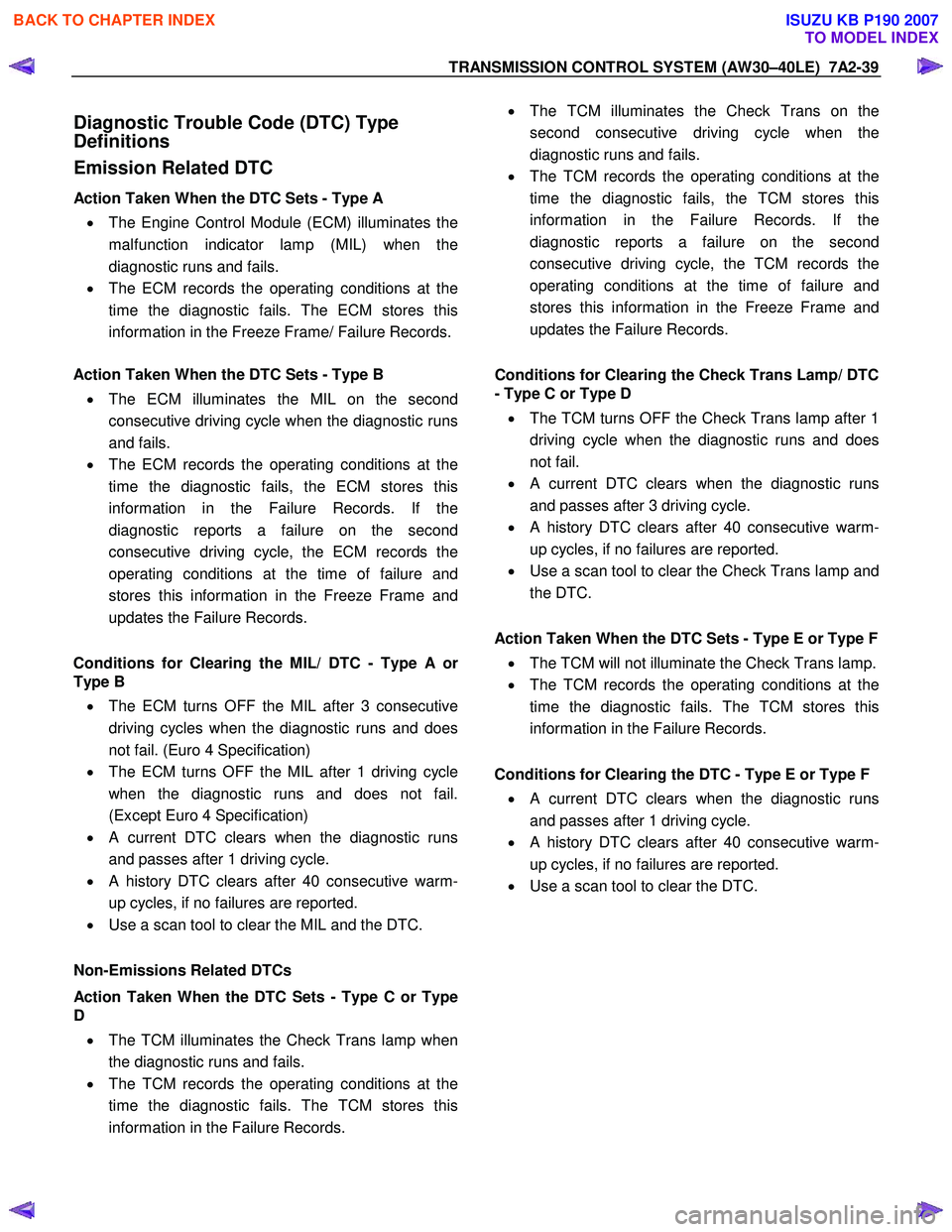
Diagnostic Trouble Code (DTC) Type
Definitions
Emission Related DTC
Action Taken When the DTC Sets - Type A
• The Engine Control Module (ECM) illuminates the
malfunction indicator lamp (MIL) when the
diagnostic runs and fails.
• The ECM records the operating conditions at the
time the diagnostic fails. The ECM stores this
information in the Freeze Frame/ Failure Records.
Action Taken When the DTC Sets - Type B
• The ECM illuminates the MIL on the second
consecutive driving cycle when the diagnostic runs
and fails.
• The ECM records the operating conditions at the
time the diagnostic fails, the ECM stores this
information in the Failure Records. If the
diagnostic reports a failure on the second
consecutive driving cycle, the ECM records the
operating conditions at the time of failure and
stores this information in the Freeze Frame and
updates the Failure Records.
Conditions for Clearing the MIL/ DTC - Type A o
r
Type B • The ECM turns OFF the MIL after 3 consecutive
driving cycles when the diagnostic runs and does
not fail. (Euro 4 Specification)
• The ECM turns OFF the MIL after 1 driving cycle
when the diagnostic runs and does not fail.
(Except Euro 4 Specification)
•
A current DTC clears when the diagnostic runs
and passes after 1 driving cycle.
• A history DTC clears after 40 consecutive warm-
up cycles, if no failures are reported.
• Use a scan tool to clear the MIL and the DTC.
Non-Emissions Related DTCs
Action Taken When the DTC Sets - Type C or Type
D
• The TCM illuminates the Check Trans lamp when
the diagnostic runs and fails.
• The TCM records the operating conditions at the
time the diagnostic fails. The TCM stores this
information in the Failure Records.
• The TCM illuminates the Check Trans on the
second consecutive driving cycle when the
diagnostic runs and fails.
• The TCM records the operating conditions at the
time the diagnostic fails, the TCM stores this
information in the Failure Records. If the
diagnostic reports a failure on the second
consecutive driving cycle, the TCM records the
operating conditions at the time of failure and
stores this information in the Freeze Frame and
updates the Failure Records.
Conditions for Clearing the Check Trans Lamp/ DTC
- Type C or Type D
• The TCM turns OFF the Check Trans lamp after 1
driving cycle when the diagnostic runs and does
not fail.
•
A current DTC clears when the diagnostic runs
and passes after 3 driving cycle.
• A history DTC clears after 40 consecutive warm-
up cycles, if no failures are reported.
• Use a scan tool to clear the Check Trans lamp and
the DTC.
Action Taken When the DTC Sets - Type E or Type F • The TCM will not illuminate the Check Trans lamp.
• The TCM records the operating conditions at the
time the diagnostic fails. The TCM stores this
information in the Failure Records.
Conditions for Clearing the DTC - Type E or Type F •
A current DTC clears when the diagnostic runs
and passes after 1 driving cycle.
• A history DTC clears after 40 consecutive warm-
up cycles, if no failures are reported.
• Use a scan tool to clear the DTC.
BACK TO CHAPTER INDEX
TO MODEL INDEX
ISUZU KB P190 2007
Page 4007 of 6020
TRANSMISSION CONTROL SYSTEM (AW30–40LE) 7A2-41
• All of the following conditions are met.
- Device Control is not operating
- Disable Normal Communication Service is receiving enable
- DTC Clear is not operating
Condition For Setting The DTC
W hen the TCM detects following conditions at 20 times
continuously.
• Ignition voltage is less than 9 volts for 1 second o
r
more continuously. (DTC P0562)
• Ignition voltage is more than 18 volts for 1 second o
r
more continuously. (DTC P0563)
Action Taken When The DTC Sets
• DTC stored.
Conditions For Clearing The DTC
• The DTC can be cleared from the TCM history by
using a scan tool.
• The DTC will be cleared from history when the
vehicle has achieved 40 warm-up cycles without a
failure reported.
•
After more than 1 second has elapsed after the
ignition key has been turned “ON”, short between
No.11 and No.4 (ground) of DLC (Data Link
Connector). Then, after 1 second, but within 6
seconds, discontinue shorting.
Diagnostic Aids
•
Inspect the wiring for poor electrical connection at the
TCM. Look for possible bent, backed out, deformed
or damaged terminals. Check for weak terminal
tension as well. Also check for a chafed wire that
could short to bare metal or other wiring.
Inspect for a broken wire inside the insulation.
• W hen diagnosing for a possible intermittent short o
r
open condition, move the wiring harness while
observing test equipment for a change.
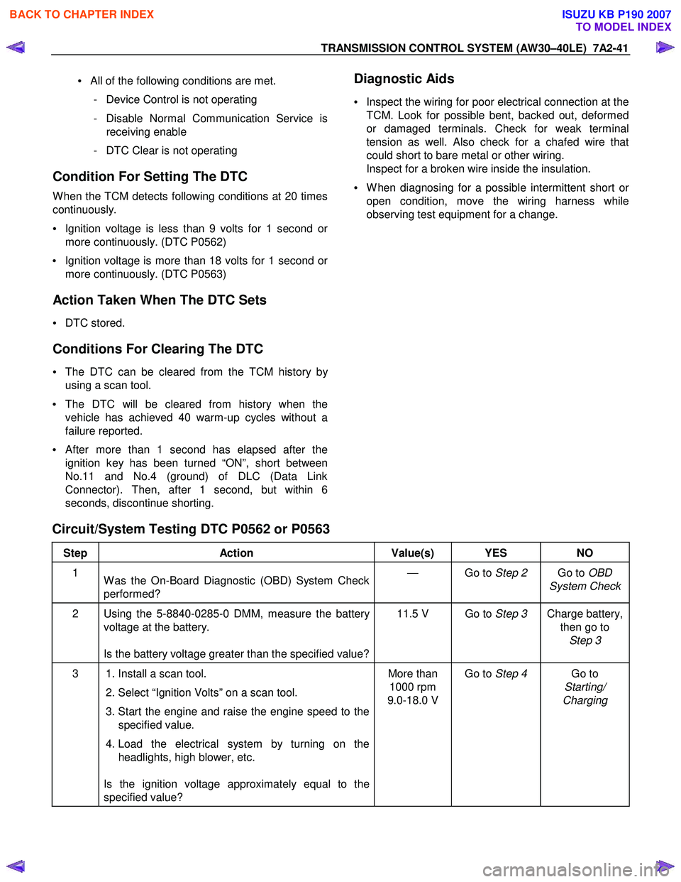
Circuit/System Testing DTC P0562 or P0563
Step Action Value(s) YES NO
1
W as the On-Board Diagnostic (OBD) System Check
performed? — Go to
Step 2 Go to OBD
System Check
2 Using the 5-8840-0285-0 DMM, measure the battery voltage at the battery.
Is the battery voltage greater than the specified value? 11.5 V Go to
Step 3 Charge battery,
then go to Step 3
3 1. Install a scan tool.
2. Select “Ignition Volts” on a scan tool.
3. Start the engine and raise the engine speed to the specified value.
4. Load the electrical system by turning on the headlights, high blower, etc.
Is the ignition voltage approximately equal to the
specified value? More than
1000 rpm
9.0-18.0 V Go to
Step 4 Go to
Starting/
Charging
BACK TO CHAPTER INDEX
TO MODEL INDEX
ISUZU KB P190 2007
Page 4008 of 6020
7A2-42 TRANSMISSION CONTROL SYSTEM (AW30–40LE)
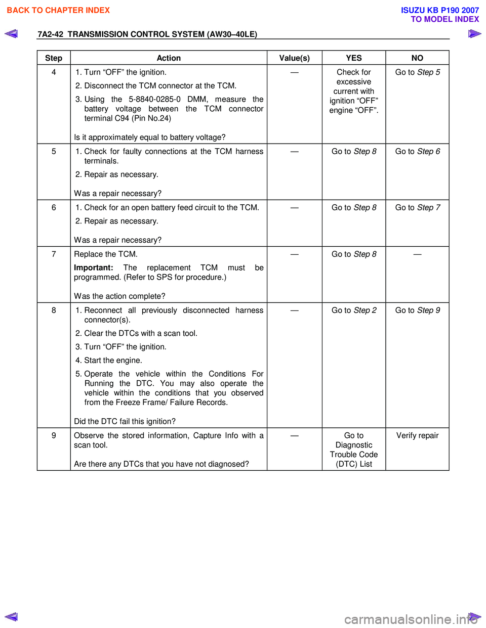
Step Action Value(s) YES NO
4 1. Turn “OFF” the ignition. 2. Disconnect the TCM connector at the TCM.
3. Using the 5-8840-0285-0 DMM, measure the battery voltage between the TCM connector
terminal C94 (Pin No.24)
Is it approximately equal to battery voltage? — Check for
excessive
current with
ignition “OFF”
engine “OFF”. Go to
Step 5
5 1. Check for faulty connections at the TCM harness
terminals.
2. Repair as necessary.
W as a repair necessary? — Go to
Step 8 Go to Step 6
6 1. Check for an open battery feed circuit to the TCM.
2. Repair as necessary.
W as a repair necessary? — Go to
Step 8 Go to Step 7
7 Replace the TCM.
Important: The replacement TCM must be
programmed. (Refer to SPS for procedure.)
W as the action complete? — Go to
Step 8 —
8 1. Reconnect all previously disconnected harness
connector(s).
2. Clear the DTCs with a scan tool.
3. Turn “OFF” the ignition.
4. Start the engine.
5. Operate the vehicle within the Conditions For Running the DTC. You may also operate the
vehicle within the conditions that you observed
from the Freeze Frame/ Failure Records.
Did the DTC fail this ignition? — Go to
Step 2 Go to Step 9
9 Observe the stored information, Capture Info with a
scan tool.
Are there any DTCs that you have not diagnosed? — Go
to
Diagnostic
Trouble Code (DTC) List Verify repair
BACK TO CHAPTER INDEX
TO MODEL INDEX
ISUZU KB P190 2007