Page 4119 of 6020
7A3-34 ON-VEHICLE SERVICE (AW30–40LE)
Valve Body Assembly and Pressure Control Solenoid
244RY00009
Removal
Preparation:
• Disconnect negative (–) battery cable.
• Drain the fluid. Refer to ATF REPLACEMENT in this section.
1. Remove the nineteen bolts and oil pan.
BACK TO CHAPTER INDEX
TO MODEL INDEX
ISUZU KB P190 2007
Page 4125 of 6020
7A3-40 ON-VEHICLE SERVICE (AW30–40LE)
Removal
NOTE: Before removing transmission and transfer
assembly from vehicle, change the transfer mode to
4 ×2 using the 4 ×4 push button switch on dash panel.
1. Disconnect battery ground cable.
2. Raise and support vehicle with suitable stands.
3. Remove the drain plug and drain the transmission oil.
4. Remove the front propeller shaft. (4 ×4 only)
NOTE: Apply alignment marks on the flange at both
front and rear sides.
5. Remove the rear propeller shaft.
NOTE: Apply alignment marks on the differential side.
RTW 77BSH000201
6. Disconnect the 2W D-4W D switch connector (1),
neutral switch connector (2), actuator connecto
r
(3) and speed sensor connector (4).
RTW 77ASH001801
RTW 77ASH001901
RTW 77ASH002001
7. Disconnect two harness clips (1) of the transfer
upper side.
1
1
RTW 77ASH001601
BACK TO CHAPTER INDEX
TO MODEL INDEX
ISUZU KB P190 2007
Page 4133 of 6020
7A3-48 ON-VEHICLE SERVICE (AW30–40LE)
22.Connect the 2W D-4W D switch connector (1),
neutral switch connector (2), actuator connecto
r
(3) and speed sensor connector (4).
RTW 77ASH001801
RTW 77ASH001901
RTW 77ASH002001
23.Install the rear propeller shaft.
NOTE: Align alignment marks on the flange.
Torque: 59 N ⋅
⋅⋅
⋅
m (6.0 kgf ⋅m/43 lb ⋅ft)
RTW 77BSH000201
24.Install the center bearing on the crossmember.
Torque: 69 N ⋅
⋅⋅
⋅
m (7.0 kgf ⋅m/51 lb ⋅ft)
25.Install the front propeller shaft.(4 ×4 only)
NOTE: Align alignment marks on the flange.
Torque: 59 N ⋅
⋅⋅
⋅
m (6.0 kgf ⋅m/43 lb ⋅ft)
26.Remove the drain plug from oil pan and drain the fluid.
27.Install the drain plug. Torque: 19 N ⋅
⋅⋅
⋅
m (1.9 kgf ⋅m/14 lb ⋅ft)
28.Pour the transmission oil.
29.Remove suitable stands.
30.Connect battery ground cable.
BACK TO CHAPTER INDEX
TO MODEL INDEX
ISUZU KB P190 2007
Page 4245 of 6020
7A1-6 CONSTRUCTION AND FUNCTION
ELECTRONIC CONTROL COMPONENTS LOCATION
4WD Only 4W D Only
Instrument panel (Meter)
Speed meter (2WD Only)
Shift position indicator lamp
POWER DRIVE, 3rd START
indicator lamp
A/T OIL TEMP indicator lamp
CHECK TRANS indicator lam
p
Brake pedal
Brake Switch
Transmission Control Module (TCM)
Electrical source
Ignition
Battery voltage
Speed sensor
Turbine sensor
Inhibitor switch
ATF thermo sensor
High clutch oil pressure switch
2-4 brake oil pressure switch
Low & Reverse brake oil pressure
switch
Line pressure solenoid
Low clutch solenoid
High clutch solenoid
2-4 brake solenoid
Low & Reverse brake solenoid
Lock-up solenoid
Transmission
Transfer Control Module
Transfer
4L mode switch
Engine
Engine speed sensor
Accelerator pedal Position Sensor
Engine Control Module (ECM)
Data link connector
Select lever
Power Drive
, 3rd Start select switch
Figure 3. Electronic Control Components Location
BACK TO CHAPTER INDEX
TO MODEL INDEX
ISUZU KB P190 2007
Page 4264 of 6020

CONSTRUCTION AND FUNCTION 7A1-25
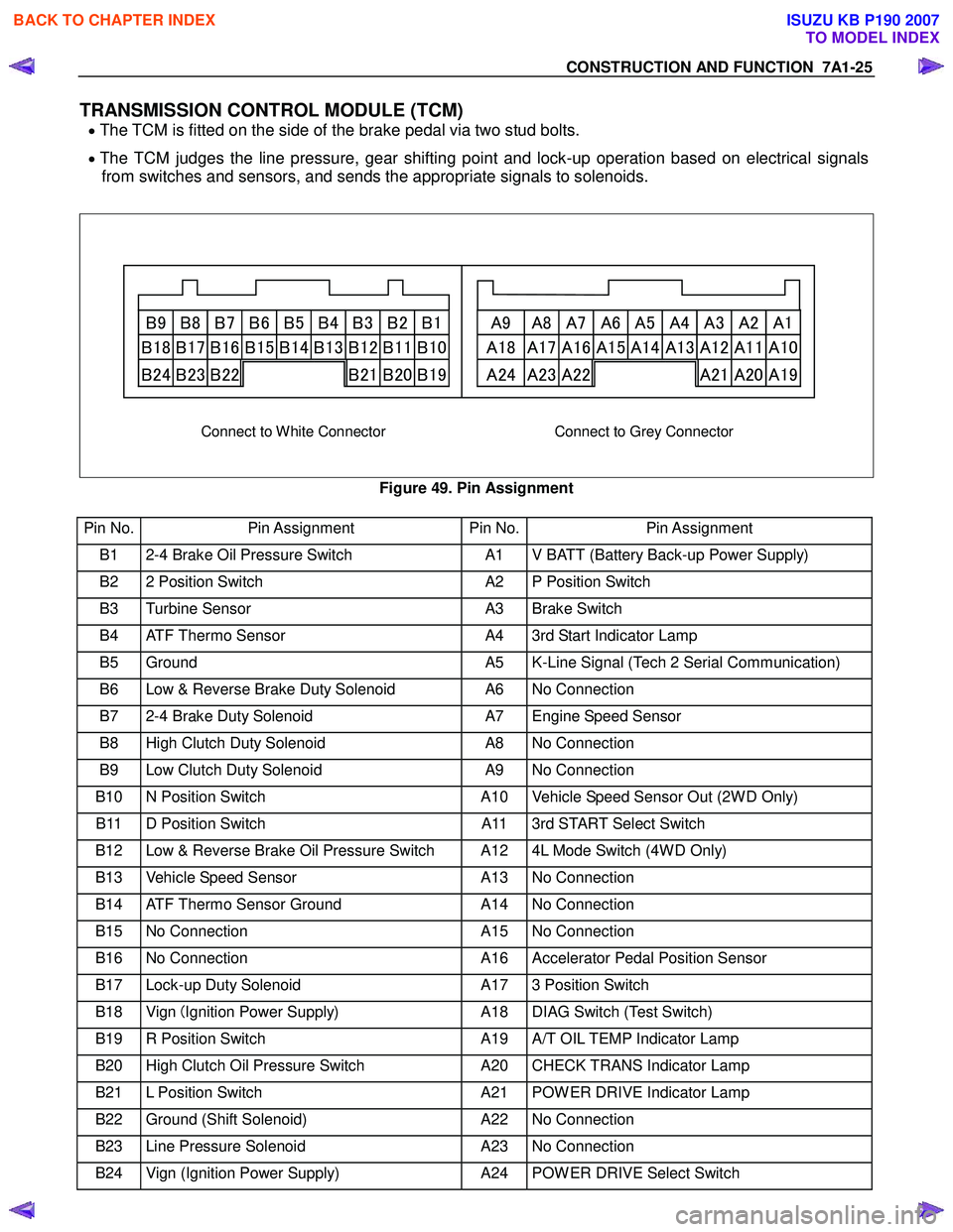
TRANSMISSION CONTROL MODULE (TCM)
• The TCM is fitted on the side of the brake pedal via two stud bolts.
• The TCM judges the line pressure, gear shifting point and lock-up operation based on electrical signals
from switches and sensors, and sends the appropriate signals to solenoids.
B9 B8 B7 B6 B5 B4 B3 B2 B1 A9 A8 A7 A6 A5 A4 A3 A2 A1
B18 B17 B16 B15 B14 B13 B12 B11 B10 A18 A17 A16 A15 A14 A13 A12 A11 A10
B24 B23 B22 B21 B20 B19 A24 A23 A22 A21 A20 A19
Connect to White Connector Connect to Grey Connector
Figure 49. Pin Assignment
Pin No. Pin Assignment Pin No.Pin Assignment
B1 2-4 Brake Oil Pressure Switch A1 V BATT (Battery Back-up Power Supply)
B2 2 Position Switch A2 P Position Switch
B3 Turbine Sensor A3 Brake Switch
B4 ATF Thermo Sensor A4 3rd Start Indicator Lamp
B5 Ground A5 K-Line Signal (Tech 2 Serial Communication)
B6 Low & Reverse Brake Duty Solenoid A6 No Connection
B7 2-4 Brake Duty Solenoid A7 Engine Speed Sensor
B8 High Clutch Duty Solenoid A8 No Connection
B9 Low Clutch Duty Solenoid A9 No Connection
B10 N Position Switch A10 Vehicle Speed Sensor Out (2W D Only)
B11 D Position Switch A11 3rd START Select Switch
B12 Low & Reverse Brake Oil Pressure Switch A12 4L Mode Switch (4W D Only)
B13 Vehicle Speed Sensor A13 No Connection
B14 ATF Thermo Sensor Ground A14 No Connection
B15 No Connection A15 No Connection
B16 No Connection A16 Accelerator Pedal Position Sensor
B17 Lock-up Duty Solenoid A17 3 Position Switch
B18 Vign (Ignition Power Supply) A18 DIAG Switch (Test Switch)
B19 R Position Switch A19 A/T OIL TEMP Indicator Lamp
B20 High Clutch Oil Pressure Switch A20 CHECK TRANS Indicator Lamp
B21 L Position Switch A21 POW ER DRIVE Indicator Lamp
B22 Ground (Shift Solenoid) A22 No Connection
B23 Line Pressure Solenoid A23 No Connection
B24 Vign (Ignition Power Supply) A24 POW ER DRIVE Select Switch
BACK TO CHAPTER INDEX
TO MODEL INDEX
ISUZU KB P190 2007
Page 4272 of 6020

CONSTRUCTION AND FUNCTION 7A1-33
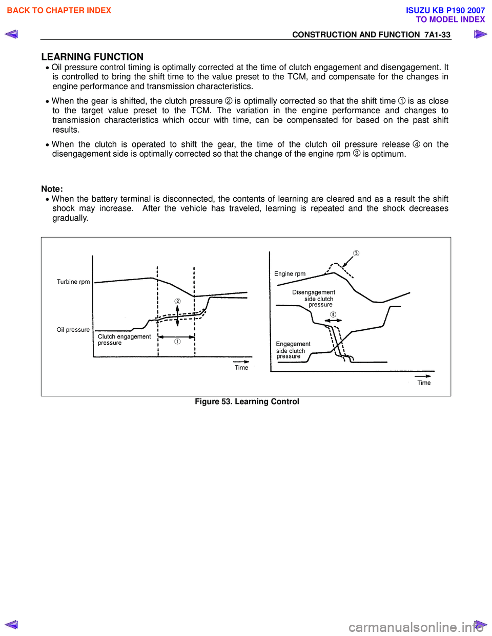
LEARNING FUNCTION
• Oil pressure control timing is optimally corrected at the time of clutch engagement and disengagement. It
is controlled to bring the shift time to the value preset to the TCM, and compensate for the changes in
engine performance and transmission characteristics.
• When the gear is shifted, the clutch pressure 2 is optimally corrected so that the shift time 1 is as close
to the target value preset to the TCM. The variation in the engine performance and changes to
transmission characteristics which occur with time, can be compensated for based on the past shift
results.
• When the clutch is operated to shift the gear, the time of the clutch oil pressure release 4 on the
disengagement side is optimally corrected so that the change of the engine rpm
3 is optimum.
Note:
• When the battery terminal is disconnected, the contents of learning are cleared and as a result the shift
shock may increase. After the vehicle has traveled, learning is repeated and the shock decreases
gradually.
Figure 53. Learning Control
BACK TO CHAPTER INDEX
TO MODEL INDEX
ISUZU KB P190 2007
Page 4301 of 6020

TRANSMISSION CONTROL SYSTEM (JR405E) 7A2-17
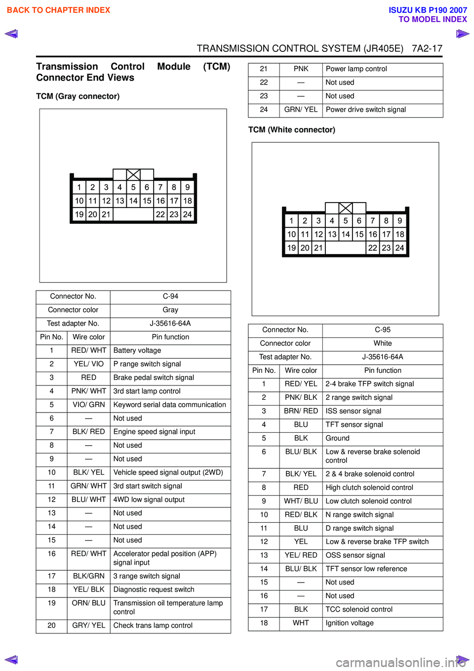
Transmission Control Module (TCM)
Connector End Views
TCM (Gray connector)
TCM (White connector)
Connector No.C-94
Connector color Gray
Test adapter No. J-35616-64A
Pin No. Wire color Pin function
1 RED/ WHT Battery voltage
2 YEL/ VIO P range switch signal
3 RED Brake pedal switch signal
4 PNK/ WHT 3rd start lamp control
5 VIO/ GRN Keyword serial data communication
6 — Not used
7 BLK/ RED Engine speed signal input
8 — Not used
9 — Not used
10 BLK/ YEL Vehicle speed signal output (2WD)
11 GRN/ WHT 3rd start switch signal
12 BLU/ WHT 4WD low signal output
13 — Not used
14 — Not used
15 — Not used
16 RED/ WHT Accelerator pedal position (APP) signal input
17 BLK/GRN 3 range switch signal
18 YEL/ BLK Diagnostic request switch
19 ORN/ BLU Transmission oil temperature lamp control
20 GRY/ YEL Check trans lamp control
1
10
19
2
11
20
3
12
21
4
13
5
14
6
15
7
16
22
8
17
23
9
18
24
21 PNK Power lamp control
22 — Not used
23 — Not used
24 GRN/ YEL Power drive switch signal
Connector No. C-95
Connector color White
Test adapter No. J-35616-64A
Pin No. Wire color Pin function
1 RED/ YEL 2-4 brake TFP switch signal
2 PNK/ BLK 2 range switch signal
3 BRN/ RED ISS sensor signal
4 BLU TFT sensor signal
5 BLK Ground
6 BLU/ BLK Low & reverse brake solenoid control
7 BLK/ YEL 2 & 4 brake solenoid control
8 RED High clutch solenoid control
9 WHT/ BLU Low clutch solenoid control
10 RED/ BLK N range switch signal 11 BLU D range switch signal
12 YEL Low & reverse brake TFP switch
13 YEL/ RED OSS sensor signal
14 BLU/ BLK TFT sensor low reference
15 — Not used
16 — Not used
17 BLK TCC solenoid control
18 WHT Ignition voltage
1
10
19
2
11
20
3
12
21
4
13
5
14
6
15
7
16
22
8
17
23
9
18
24
BACK TO CHAPTER INDEX
TO MODEL INDEX
ISUZU KB P190 2007
Page 4302 of 6020

7A2-18 TRANSMISSION CONTROL SYSTEM (JR405E)
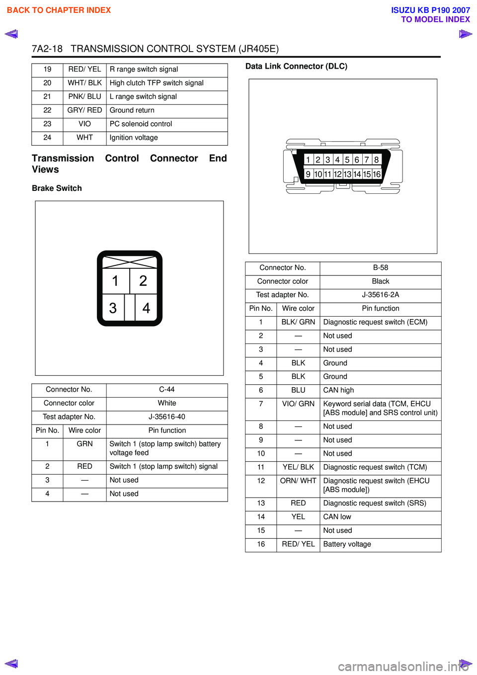
Transmission Control Connector End
Views
Brake Switch Data Link Connector (DLC)
19 RED/ YEL R range switch signal
20 WHT/ BLK High clutch TFP switch signal
21 PNK/ BLU L range switch signal
22 GRY/ RED Ground return
23 VIO PC solenoid control
24 WHT Ignition voltage
Connector No. C-44
Connector color White
Test adapter No. J-35616-40
Pin No. Wire color Pin function
1 GRN Switch 1 (stop lamp switch) battery voltage feed
2 RED Switch 1 (stop lamp switch) signal
3—Not used
4—Not used
21
34
Connector No. B-58
Connector color Black
Test adapter No. J-35616-2A
Pin No. Wire color Pin function
1 BLK/ GRN Diagnostic request switch (ECM)
2 — Not used
3 — Not used
4 BLK Ground
5 BLK Ground
6 BLU CAN high
7 VIO/ GRN Keyword serial data (TCM, EHCU [ABS module] and SRS control unit)
8 — Not used
9 — Not used
10 — Not used
11 YEL/ BLK Diagnostic request switch (TCM)
12 ORN/ WHT Diagnostic request switch (EHCU [ABS module])
13 RED Diagnostic request switch (SRS)
14 YEL CAN low
15 — Not used
16 RED/ YEL Battery voltage
87654321
16151413121110
9
BACK TO CHAPTER INDEX
TO MODEL INDEX
ISUZU KB P190 2007