2007 ISUZU KB P190 relay
[x] Cancel search: relayPage 1191 of 6020
Engine Control System (4JH1) 6E-157
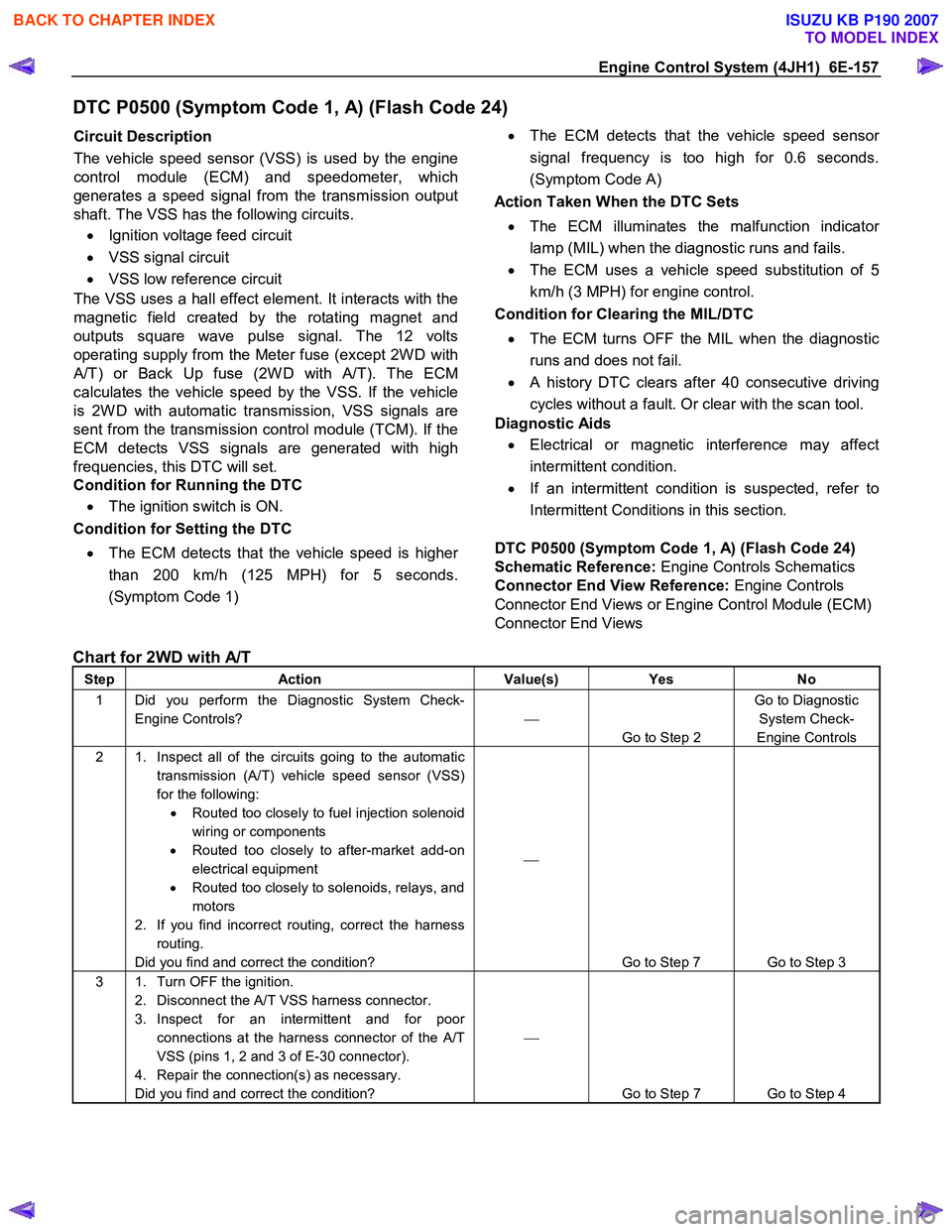
DTC P0500 (Symptom Code 1, A) (Flash Code 24)
Circuit Description
The vehicle speed sensor (VSS) is used by the engine
control module (ECM) and speedometer, which
generates a speed signal from the transmission output
shaft. The VSS has the following circuits.
• Ignition voltage feed circuit
• VSS signal circuit
• VSS low reference circuit
The VSS uses a hall effect element. It interacts with the
magnetic field created by the rotating magnet and
outputs square wave pulse signal. The 12 volts
operating supply from the Meter fuse (except 2W D with
A/T) or Back Up fuse (2W D with A/T). The ECM
calculates the vehicle speed by the VSS. If the vehicle
is 2W D with automatic transmission, VSS signals are
sent from the transmission control module (TCM). If the
ECM detects VSS signals are generated with high
frequencies, this DTC will set.
Condition for Running the DTC
• The ignition switch is ON.
Condition for Setting the DTC
• The ECM detects that the vehicle speed is highe
r
than 200 km/h (125 MPH) for 5 seconds.
(Symptom Code 1)
•
The ECM detects that the vehicle speed senso
r
signal frequency is too high for 0.6 seconds.
(Symptom Code A)
Action Taken When the DTC Sets
• The ECM illuminates the malfunction indicato
r
lamp (MIL) when the diagnostic runs and fails.
• The ECM uses a vehicle speed substitution of 5
km/h (3 MPH) for engine control.
Condition for Clearing the MIL/DTC
• The ECM turns OFF the MIL when the diagnostic
runs and does not fail.
• A history DTC clears after 40 consecutive driving
cycles without a fault. Or clear with the scan tool.
Diagnostic Aids
• Electrical or magnetic interference may affect
intermittent condition.
• If an intermittent condition is suspected, refer to
Intermittent Conditions in this section.
DTC P0500 (Symptom Code 1, A) (Flash Code 24)
Schematic Reference: Engine Controls Schematics
Connector End View Reference: Engine Controls
Connector End Views or Engine Control Module (ECM)
Connector End Views
Chart for 2WD with A/T
Step Action Value(s) Yes No
1 Did you perform the Diagnostic System Check-
Engine Controls?
Go to Step 2 Go to Diagnostic
System Check-
Engine Controls
2 1. Inspect all of the circuits going to the automatic transmission (A/T) vehicle speed sensor (VSS)
for the following: • Routed too closely to fuel injection solenoid
wiring or components
• Routed too closely to after-market add-on
electrical equipment
• Routed too closely to solenoids, relays, and
motors
2. If you find incorrect routing, correct the harness routing.
Did you find and correct the condition?
Go to Step 7 Go to Step 3
3 1. Turn OFF the ignition. 2. Disconnect the A/T VSS harness connector.
3. Inspect for an intermittent and for poor connections at the harness connector of the A/T
VSS (pins 1, 2 and 3 of E-30 connector).
4. Repair the connection(s) as necessary.
Did you find and correct the condition?
Go to Step 7 Go to Step 4
BACK TO CHAPTER INDEX
TO MODEL INDEX
ISUZU KB P190 2007
Page 1192 of 6020
6E-158 Engine Control System (4JH1)
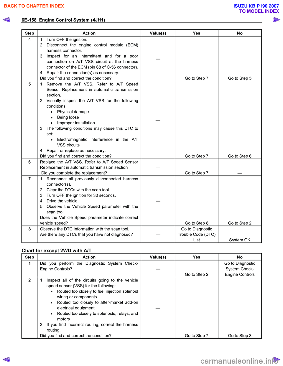
Step Action Value(s) Yes No
4 1. Turn OFF the ignition.
2. Disconnect the engine control module (ECM) harness connector.
3. Inspect for an intermittent and for a poor connection on A/T VSS circuit at the harness
connector of the ECM (pin 68 of C-56 connector).
4. Repair the connection(s) as necessary.
Did you find and correct the condition?
Go to Step 7 Go to Step 5
5 1. Remove the A/T VSS. Refer to A/T Speed Sensor Replacement in automatic transmission
section.
2. Visually inspect the A/T VSS for the following conditions: • Physical damage
• Being loose
• Improper installation
3. The following conditions may cause this DTC to set: • Electromagnetic interference in the A/T
VSS circuits
4. Repair or replace as necessary.
Did you find and correct the condition?
Go to Step 7 Go to Step 6
6 Replace the A/T VSS. Refer to A/T Speed Sensor Replacement in automatic transmission section
Did you complete the replacement?
Go to Step 7
7 1. Reconnect all previously disconnected harness
connector(s).
2. Clear the DTCs with the scan tool.
3. Turn OFF the ignition for 30 seconds.
4. Drive the vehicle.
5. Observe the Vehicle Speed parameter with the scan tool.
Does the Vehicle Speed parameter indicate correct
vehicle speed?
Go to Step 8 Go to Step 2
8 Observe the DTC Information with the scan tool. Are there any DTCs that you have not diagnosed? Go to Diagnostic
Trouble Code (DTC) List System OK
Chart for except 2WD with A/T
Step Action Value(s) Yes No
1 Did you perform the Diagnostic System Check-
Engine Controls?
Go to Step 2 Go to Diagnostic
System Check-
Engine Controls
2 1. Inspect all of the circuits going to the vehicle speed sensor (VSS) for the following: • Routed too closely to fuel injection solenoid
wiring or components
• Routed too closely to after-market add-on
electrical equipment
• Routed too closely to solenoids, relays, and
motors
2. If you find incorrect routing, correct the harness routing.
Did you find and correct the condition?
Go to Step 7 Go to Step 3
BACK TO CHAPTER INDEX
TO MODEL INDEX
ISUZU KB P190 2007
Page 1200 of 6020
6E-166 Engine Control System (4JH1)
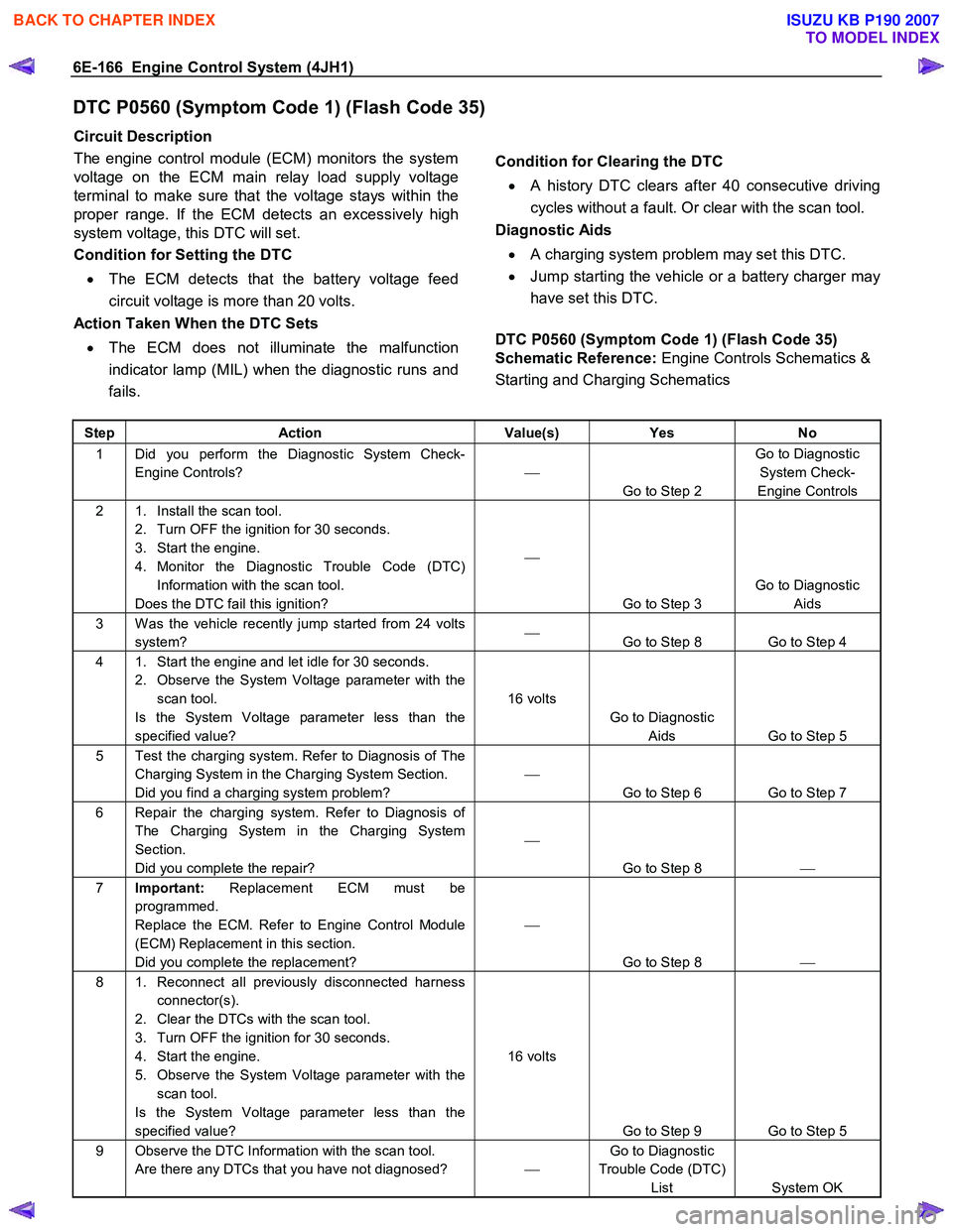
DTC P0560 (Symptom Code 1) (Flash Code 35)
Circuit Description
The engine control module (ECM) monitors the system
voltage on the ECM main relay load supply voltage
terminal to make sure that the voltage stays within the
proper range. If the ECM detects an excessively high
system voltage, this DTC will set.
Condition for Setting the DTC
• The ECM detects that the battery voltage feed
circuit voltage is more than 20 volts.
Action Taken When the DTC Sets
• The ECM does not illuminate the malfunction
indicator lamp (MIL) when the diagnostic runs and
fails.
Condition for Clearing the DTC • A history DTC clears after 40 consecutive driving
cycles without a fault. Or clear with the scan tool.
Diagnostic Aids
• A charging system problem may set this DTC.
• Jump starting the vehicle or a battery charger may
have set this DTC.
DTC P0560 (Symptom Code 1) (Flash Code 35)
Schematic Reference: Engine Controls Schematics &
Starting and Charging Schematics
Step Action Value(s) Yes No
1 Did you perform the Diagnostic System Check-
Engine Controls?
Go to Step 2 Go to Diagnostic
System Check-
Engine Controls
2 1. Install the scan tool. 2. Turn OFF the ignition for 30 seconds.
3. Start the engine.
4. Monitor the Diagnostic Trouble Code (DTC) Information with the scan tool.
Does the DTC fail this ignition?
Go to Step 3 Go to Diagnostic
Aids
3 W as the vehicle recently jump started from 24 volts system?
Go to Step 8 Go to Step 4
4 1. Start the engine and let idle for 30 seconds.
2. Observe the System Voltage parameter with the scan tool.
Is the System Voltage parameter less than the
specified value? 16 volts
Go to Diagnostic Aids Go to Step 5
5 Test the charging system. Refer to Diagnosis of The Charging System in the Charging System Section.
Did you find a charging system problem?
Go to Step 6 Go to Step 7
6 Repair the charging system. Refer to Diagnosis of The Charging System in the Charging System
Section.
Did you complete the repair?
Go to Step 8
7 Important: Replacement ECM must be
programmed.
Replace the ECM. Refer to Engine Control Module
(ECM) Replacement in this section.
Did you complete the replacement?
Go to Step 8
8 1. Reconnect all previously disconnected harness
connector(s).
2. Clear the DTCs with the scan tool.
3. Turn OFF the ignition for 30 seconds.
4. Start the engine.
5. Observe the System Voltage parameter with the scan tool.
Is the System Voltage parameter less than the
specified value? 16 volts
Go to Step 9 Go to Step 5
9 Observe the DTC Information with the scan tool. Are there any DTCs that you have not diagnosed? Go to Diagnostic
Trouble Code (DTC) List System OK
BACK TO CHAPTER INDEX
TO MODEL INDEX
ISUZU KB P190 2007
Page 1201 of 6020
Engine Control System (4JH1) 6E-167
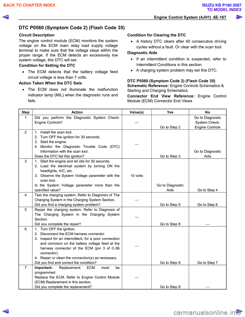
DTC P0560 (Symptom Code 2) (Flash Code 35)
Circuit Description
The engine control module (ECM) monitors the system
voltage on the ECM main relay load supply voltage
terminal to make sure that the voltage stays within the
proper range. If the ECM detects an excessively lo
w
system voltage, this DTC will set.
Condition for Setting the DTC
• The ECM detects that the battery voltage feed
circuit voltage is less than 7 volts.
Action Taken When the DTC Sets
• The ECM does not illuminate the malfunction
indicator lamp (MIL) when the diagnostic runs and
fails.
Condition for Clearing the DTC
• A history DTC clears after 40 consecutive driving
cycles without a fault. Or clear with the scan tool.
Diagnostic Aids
• If an intermittent condition is suspected, refer to
Intermittent Conditions in this section.
• A charging system problem may set this DTC.
DTC P0560 (Symptom Code 2) (Flash Code 35)
Schematic Reference: Engine Controls Schematics &
Starting and Charging Schematics
Connector End View Reference: Engine Control
Module (ECM) Connector End Views
Step Action Value(s) Yes No
1 Did you perform the Diagnostic System Check-
Engine Controls?
Go to Step 2 Go to Diagnostic
System Check-
Engine Controls
2 1. Install the scan tool. 2. Turn OFF the ignition for 30 seconds.
3. Start the engine.
4. Monitor the Diagnostic Trouble Code (DTC) Information with the scan tool.
Does the DTC fail this ignition?
Go to Step 3 Go to Diagnostic
Aids
3 1. Start the engine and let idle for 30 seconds. 2. Load the electrical system by turning ON the headlights, A/C, etc.
3. Observe the System Voltage parameter with the scan tool.
Is the System Voltage parameter more than the
specified value? 10 volts
Go to Diagnostic Aids Go to Step 4
4 Test the charging system. Refer to Diagnosis of The Charging System in the Charging System Section.
Did you find a charging system problem?
Go to Step 5 Go to Step 6
5 Repair the charging system. Refer to Diagnosis of The Charging System in the Charging System
Section.
Did you complete the repair?
Go to Step 8
6 1. Turn OFF the ignition.
2. Disconnect the ECM harness connector.
3. Inspect for an intermittent, for a poor connection and corrosion on the battery voltage feed at the
harness connector of the ECM (pin 3 of C-56
connector).
4. Repair or clean the connection(s) as necessary.
Did you find and correct the condition?
Go to Step 8 Go to Step 7
7 Important: Replacement ECM must be
programmed.
Replace the ECM. Refer to Engine Control Module
(ECM) Replacement in this section.
Did you complete the replacement?
Go to Step 8
BACK TO CHAPTER INDEX
TO MODEL INDEX
ISUZU KB P190 2007
Page 1203 of 6020
Engine Control System (4JH1) 6E-169
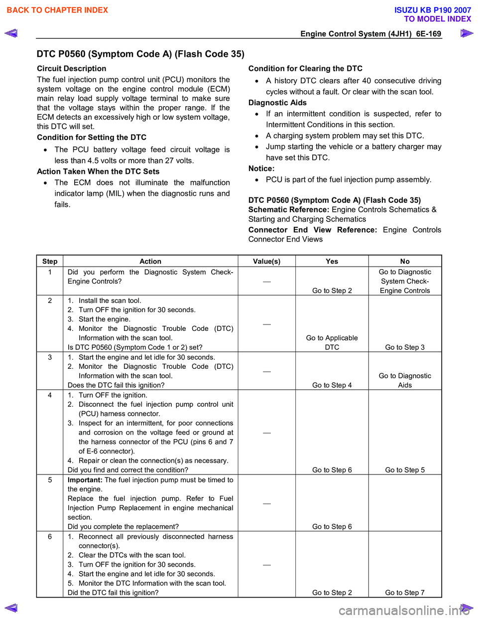
DTC P0560 (Symptom Code A) (Flash Code 35)
Circuit Description
The fuel injection pump control unit (PCU) monitors the
system voltage on the engine control module (ECM)
main relay load supply voltage terminal to make sure
that the voltage stays within the proper range. If the
ECM detects an excessively high or low system voltage,
this DTC will set.
Condition for Setting the DTC
• The PCU battery voltage feed circuit voltage is
less than 4.5 volts or more than 27 volts.
Action Taken When the DTC Sets
• The ECM does not illuminate the malfunction
indicator lamp (MIL) when the diagnostic runs and
fails.
Condition for Clearing the DTC
• A history DTC clears after 40 consecutive driving
cycles without a fault. Or clear with the scan tool.
Diagnostic Aids
• If an intermittent condition is suspected, refer to
Intermittent Conditions in this section.
• A charging system problem may set this DTC.
• Jump starting the vehicle or a battery charger may
have set this DTC.
Notice:
• PCU is part of the fuel injection pump assembly.
DTC P0560 (Symptom Code A) (Flash Code 35)
Schematic Reference: Engine Controls Schematics &
Starting and Charging Schematics
Connector End View Reference: Engine Controls
Connector End Views
Step Action Value(s) Yes No
1 Did you perform the Diagnostic System Check-
Engine Controls?
Go to Step 2 Go to Diagnostic
System Check-
Engine Controls
2 1. Install the scan tool. 2. Turn OFF the ignition for 30 seconds.
3. Start the engine.
4. Monitor the Diagnostic Trouble Code (DTC) Information with the scan tool.
Is DTC P0560 (Symptom Code 1 or 2) set?
Go to Applicable DTC Go to Step 3
3 1. Start the engine and let idle for 30 seconds. 2. Monitor the Diagnostic Trouble Code (DTC) Information with the scan tool.
Does the DTC fail this ignition?
Go to Step 4 Go to Diagnostic
Aids
4 1. Turn OFF the ignition. 2. Disconnect the fuel injection pump control unit (PCU) harness connector.
3. Inspect for an intermittent, for poor connections and corrosion on the voltage feed or ground at
the harness connector of the PCU (pins 6 and 7
of E-6 connector).
4. Repair or clean the connection(s) as necessary.
Did you find and correct the condition?
Go to Step 6 Go to Step 5
5 Important: The fuel injection pump must be timed to
the engine.
Replace the fuel injection pump. Refer to Fuel
Injection Pump Replacement in engine mechanical
section.
Did you complete the replacement?
Go to Step 6
6 1. Reconnect all previously disconnected harness connector(s).
2. Clear the DTCs with the scan tool.
3. Turn OFF the ignition for 30 seconds.
4. Start the engine and let idle for 30 seconds.
5. Monitor the DTC Information with the scan tool.
Did the DTC fail this ignition?
Go to Step 2 Go to Step 7
BACK TO CHAPTER INDEX
TO MODEL INDEX
ISUZU KB P190 2007
Page 1205 of 6020
Engine Control System (4JH1) 6E-171
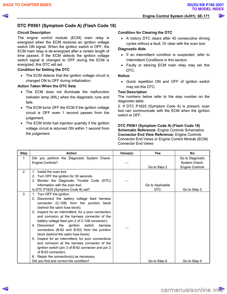
DTC P0561 (Symptom Code A) (Flash Code 18)
Circuit Description
The engine control module (ECM) main relay is
energized when the ECM receives an ignition voltage
switch ON signal. W hen the ignition switch is OFF, the
ECM main relay is de-energized after a certain length o
f
time passed. If the ECM detects the ignition voltage
switch signal is changed to OFF during the ECM is
energized, this DTC will set.
Condition for Setting the DTC
• The ECM detects that the ignition voltage circuit is
changed ON to OFF during initialization.
Action Taken When the DTC Sets
• The ECM does not illuminate the malfunction
indicator lamp (MIL) when the diagnostic runs and
fails.
• The ECM turns OFF the ECM if the ignition voltage
circuit is OFF even 1 second passes from the
judgement.
• The ECM limits fuel injection quantity if the ignition
voltage circuit is returned ON within 1 second from
the judgement.
Condition for Clearing the DTC
• A history DTC clears after 40 consecutive driving
cycles without a fault. Or clear with the scan tool.
Diagnostic Aids
• If an intermittent condition is suspected, refer to
Intermittent Conditions in this section.
• Faulty or sticking ECM main relay may set this
DTC.
Notice:
• Quick repetition ON and OFF of ignition switch
may set this DTC.
Test Description
The numbers below refer to the step number on the
diagnostic table.
2. If DTC P1625 (Symptom Code A) is present, scan
tool can communicate with the ECM when the ignition
switch is OFF.
DTC P0561 (Symptom Code A) (Flash Code 18)
Schematic Reference: Engine Controls Schematics
Connector End View Reference: Engine Controls
Connector End Views or Engine Control Module (ECM)
Connector End Views
Step Action Value(s) Yes No
1 Did you perform the Diagnostic System Check-
Engine Controls?
Go to Step 2 Go to Diagnostic
System Check-
Engine Controls
2 1. Install the scan tool. 2. Turn OFF the ignition for 30 seconds.
3. Monitor the Diagnostic Trouble Code (DTC) Information with the scan tool.
Is DTC P1625 (Symptom Code B) set?
Go to Applicable DTC Go to Step 3
3 1. Turn OFF the ignition. 2. Disconnect the battery voltage feed harness connector (C-108) from the junction block
(behind the cabin fuse block).
3. Inspect for an intermittent, for a poor connection and corrosion at the harness connector of the
battery voltage feed (pin 2 of C-108 connector).
4. Disconnect the ignition switch harness connectors (B-62 and B-63) from the junction
block (behind the cabin fuse block).
5. Inspect for an intermittent, for poor connections and corrosion at the harness connector of the
ignition switch (pin 3 of B-62 connector and pin 3
of B-63 connector).
6. Repair the connection(s) as necessary.
Did you find and correct the condition?
Go to Step 6 Go to Step 4
BACK TO CHAPTER INDEX
TO MODEL INDEX
ISUZU KB P190 2007
Page 1207 of 6020
Engine Control System (4JH1) 6E-173
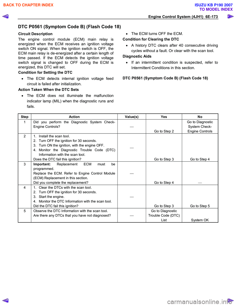
DTC P0561 (Symptom Code B) (Flash Code 18)
Circuit Description
The engine control module (ECM) main relay is
energized when the ECM receives an ignition voltage
switch ON signal. W hen the ignition switch is OFF, the
ECM main relay is de-energized after a certain length o
f
time passed. If the ECM detects the ignition voltage
switch signal is changed to OFF during the ECM is
energized, this DTC will set.
Condition for Setting the DTC
• The ECM detects internal ignition voltage feed
circuit is failed after initialization.
Action Taken When the DTC Sets
• The ECM does not illuminate the malfunction
indicator lamp (MIL) when the diagnostic runs and
fails.
•
The ECM turns OFF the ECM.
Condition for Clearing the DTC
• A history DTC clears after 40 consecutive driving
cycles without a fault. Or clear with the scan tool.
Diagnostic Aids
• If an intermittent condition is suspected, refer to
Intermittent Conditions in this section.
DTC P0561 (Symptom Code B) (Flash Code 18)
Step Action Value(s) Yes No
1 Did you perform the Diagnostic System Check-
Engine Controls?
Go to Step 2 Go to Diagnostic
System Check-
Engine Controls
2 1. Install the scan tool. 2. Turn OFF the ignition for 30 seconds.
3. Turn ON the ignition, with the engine OFF.
4. Monitor the Diagnostic Trouble Code (DTC) Information with the scan tool.
Does the DTC fail this ignition?
Go to Step 3 Go to Step 4
3 Important: Replacement ECM must be
programmed.
Replace the ECM. Refer to Engine Control Module
(ECM) Replacement in this section.
Did you complete the replacement?
Go to Step 4
4 1. Clear the DTCs with the scan tool.
2. Turn OFF the ignition for 30 seconds.
3. Start the engine.
4. Monitor the DTC Information with the scan tool.
Did the DTC fail this ignition?
Go to Step 3 Go to Step 5
5 Observe the DTC Information with the scan tool. Are there any DTCs that you have not diagnosed? Go to Diagnostic
Trouble Code (DTC) List System OK
BACK TO CHAPTER INDEX
TO MODEL INDEX
ISUZU KB P190 2007
Page 1210 of 6020
6E-176 Engine Control System (4JH1)
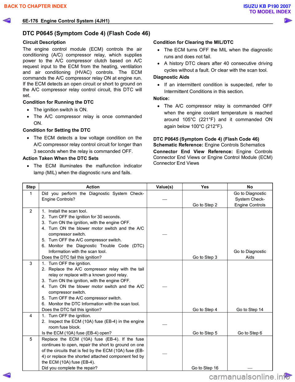
DTC P0645 (Symptom Code 4) (Flash Code 46)
Circuit Description
The engine control module (ECM) controls the ai
r
conditioning (A/C) compressor relay, which supplies
power to the A/C compressor clutch based on A/C
request input to the ECM from the heating, ventilation
and air conditioning (HVAC) controls. The ECM
commands the A/C compressor relay ON at engine run.
If the ECM detects an open circuit or short to ground on
the A/C compressor relay control circuit, this DTC will
set.
Condition for Running the DTC
• The ignition switch is ON.
• The A/C compressor relay is once commanded
ON.
Condition for Setting the DTC
• The ECM detects a low voltage condition on the
A/C compressor relay control circuit for longer than
3 seconds when the relay is commanded OFF.
Action Taken When the DTC Sets
• The ECM illuminates the malfunction indicato
r
lamp (MIL) when the diagnostic runs and fails.
Condition for Clearing the MIL/DTC
• The ECM turns OFF the MIL when the diagnostic
runs and does not fail.
• A history DTC clears after 40 consecutive driving
cycles without a fault. Or clear with the scan tool.
Diagnostic Aids
• If an intermittent condition is suspected, refer to
Intermittent Conditions in this section.
Notice:
• The A/C compressor relay is commanded OFF
when the engine coolant temperature is reached
around 105°C (221°F) and it commanded ON
again below 100°C (212°F).
DTC P0645 (Symptom Code 4) (Flash Code 46)
Schematic Reference: Engine Controls Schematics
Connector End View Reference: Engine Controls
Connector End Views or Engine Control Module (ECM)
Connector End Views
Step Action Value(s) Yes No
1 Did you perform the Diagnostic System Check-
Engine Controls?
Go to Step 2 Go to Diagnostic
System Check-
Engine Controls
2 1. Install the scan tool. 2. Turn OFF the ignition for 30 seconds.
3. Turn ON the ignition, with the engine OFF.
4. Turn ON the blower motor switch and the A/C compressor switch.
5. Turn OFF the A/C compressor switch.
6. Monitor the Diagnostic Trouble Code (DTC) Information with the scan tool.
Does the DTC fail this ignition?
Go to Step 3 Go to Diagnostic
Aids
3 1. Turn OFF the ignition. 2. Replace the A/C compressor relay with the tail relay or replace with a known good relay.
3. Turn ON the ignition, with the engine OFF.
4. Turn ON the blower motor switch and the A/C compressor switch.
5. Turn OFF the A/C compressor switch.
6. Monitor the DTC Information with the scan tool.
Does the DTC fail this ignition?
Go to Step 4 Go to Step 14
4 1. Turn OFF the ignition. 2. Inspect the ECM (10A) fuse (EB-4) in the engine room fuse block.
Is the ECM (10A) fuse (EB-4) open?
Go to Step 5 Go to Step 6
5 Replace the ECM (10A) fuse (EB-4). If the fuse continues to open, repair the short to ground on one
of the circuits that is fed by the ECM (10A) fuse (EB-
4) or replace the shorted attached component fed by
the ECM (10A) fuse (EB-4).
Did you complete the repair?
Go to Step 16
BACK TO CHAPTER INDEX
TO MODEL INDEX
ISUZU KB P190 2007