2007 ISUZU KB P190 relay
[x] Cancel search: relayPage 626 of 6020

BRAKE CONTROL SYSTEM 5A-33
Diagnostic Trouble Codes
Choose and trace an appropriate flowchart by the
numbers listed below to find the fault and repair.
Note:
A DTC cannot be erased when the DTC is present.
Warning Lamp System Control Main Items
DTC
(Flash Code) Description
ABS Brake
(EBD) ABS EBD
-
(12) Normal Condition
× × -
C0221
(21) Front Right W heel Speed Sensor
Short Circuit or Circuit Open ×*A × Sensor or W iring
C0222
(22) Front Right W heel Speed Sensor
Signal Malfunction *B ×*A × Sensor or install condition
C0225
(25) Front Left W heel Speed Sensor Short
Circuit or Circuit Open ×*A × Sensor or W iring
C0226
(26) Front Left W heel Speed Sensor Signal
Malfunction *B ×*A × Sensor or install condition
C0231
(31) Rear Right W heel Speed Sensor Short
Circuit or Circuit Open ×*A × Sensor or W iring
C0232
(32) Rear Right W heel Speed Sensor
Signal Malfunction *B ×*A × Sensor or install condition
C0235
(35) Rear Left W heel Speed Sensor Short
Circuit or Circuit Open ×*A × Sensor or W iring
C0236
(36) Rear Left W heel Speed Sensor Signal
Malfunction *B ×*A × Sensor or install condition
C0238
(38) Front Speed Sensor Correlation
× × Vehicle , Sensor or Tire
C0241
(41) Front Right Hold Solenoid Valve Circuit
× × Solenoid (EHCU)
C0242
(42) Front Right Release Solenoid Valve
Circuit × × Solenoid (EHCU)
C0245
(45) Front Left Hold Solenoid Valve Circuit
× × Solenoid (EHCU)
C0246
(46) Front Left Release Solenoid Valve
Circuit × × Solenoid (EHCU)
C0251
(51) Rear Hold Solenoid Valve Circuit
× × Solenoid (EHCU)
C0252
(52) Rear Release Solenoid Valve Circuit
× × Solenoid (EHCU)
×
C0265
(65) Valve Relay Circuit Malfunction
×
× Relay (EHCU)
C0267
(67) Return Pump Circuit Malfunction
× Motor (EHCU)
C0271
(71) ECU Malfunction
× × EHCU
C0276
(76) G Sensor Malfunction
× × Sensor or W iring
BACK TO CHAPTER INDEX
TO MODEL INDEX
ISUZU KB P190 2007
Page 665 of 6020
5A-72 BRAKE CONTROL SYSTEM
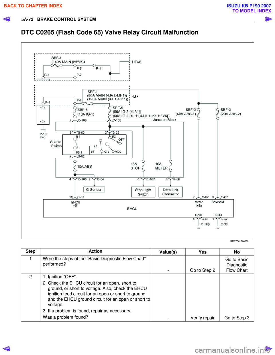
DTC C0265 (Flash Code 65) Valve Relay Circuit Malfunction
RTW 75ALF000301
Step Action Value(s) Yes No
1 W ere the steps of the “Basic Diagnostic Flow Chart”
performed?
- Go to Step 2 Go to Basic
Diagnostic
Flow Chart
2 1. Ignition “OFF”.
2. Check the EHCU circuit for an open, short to ground, or short to voltage. Also, check the EHCU
ignition feed circuit for an open or short to ground
and the EHCU ground circuit for an open or short to
voltage.
3. If a problem is found, repair as necessary. W as a problem found? - Verify repair Go to Step 3
BACK TO CHAPTER INDEX
TO MODEL INDEX
ISUZU KB P190 2007
Page 788 of 6020

TROUBLESHOOTING 6 – 3
1. Hard Starting
Inspect the following items before diagnosis.
1. The battery conditions. The terminal connection condition.
The battery charge condition or battery power weakness.
2. The fan belt loosen or broken.
3. The main fuse condition (open or not).
4. Fuel quantity level.
1 –1 Starter motor inoperative
Step Action Value(s) Yes No
1 Check the starter switch. Does the starter switch work? —
Go to Step 2 Repair or
replace the
starter switch
2 Check the starter relay. Does the starter relay work? —
Go to Step 3 Repair or
replace the
starter relay
3 Check the magnetic switch. Does the magnetic switch work? —
Go to Step 4 Repair or
replace the magnetic switch
4 Check the pinion gear condition on the starter motor. Was the condition normal? —
Go to Step 5 Replace the
pinion gear
5 Check the brush wear or brush spring weakness. Was the condition normal? —
Replace the
starter motor assembly Repair or
replace the
brush or brush spring
1-2 Starter motor operates but engine does not turn over
Step Action Value(s) Yes No
1 Check the engine internal seizure. Was the engine seized? —
Repair or
replace seized parts Check other
DTC by Tech 2 and go to
indicated DTC
BACK TO CHAPTER INDEX
TO MODEL INDEX
ISUZU KB P190 2007
Page 1002 of 6020
SECTION 6D
ENGINE ELECTRICAL
TABLE OF CONTENTS
PAGE
Main Data and Specifications ......................................................................................... 6D - 2
General Description ........................................................................................................ 6D - 3
Torque Specifications ..................................................................................................... 6D - 5
Generator ...................................................................................................................... ... 6D - 7
Removal and Installation ............................................................................................ 6D - 7
Disassembly ................................................................................................................ 6D - 9
Inspection and Repair ................................................................................................. 6D - 12
Reassembly ................................................................................................................. 6D - 18
Starter Motor .................................................................................................................. .. 6D - 22
Removal and Installation ............................................................................................ 6D - 22
Disassembly ................................................................................................................ 6D - 23
Inspection and Repair ................................................................................................. 6D - 26
Reassembly ................................................................................................................. 6D - 29
Pre-heating System ......................................................................................................... 6D -33
Inspection and Repair ................................................................................................. 6D -33
Glow Relay ................................................................................................................... 6D -33
Glow Plug..................................................................................................................... 6D -33
EGR System ................................................................................................................. 6D -33
ENGINE ELECTRICAL 6D – 1
BACK TO CHAPTER INDEX
TO MODEL INDEX
ISUZU KB P190 2007
Page 1034 of 6020
ENGINE ELECTRICAL 6D – 33
PRE-HEATING SYSTEM
INSPECTION AND REPAIR
Make the necessary adjustments, repairs, and part replacement if excessive wear of damage is discovered during
inspection.
VISUAL CHECK
Check the main fuses and glow indicator for damage.
Replace the part(s) if required.
GLOW RELAY
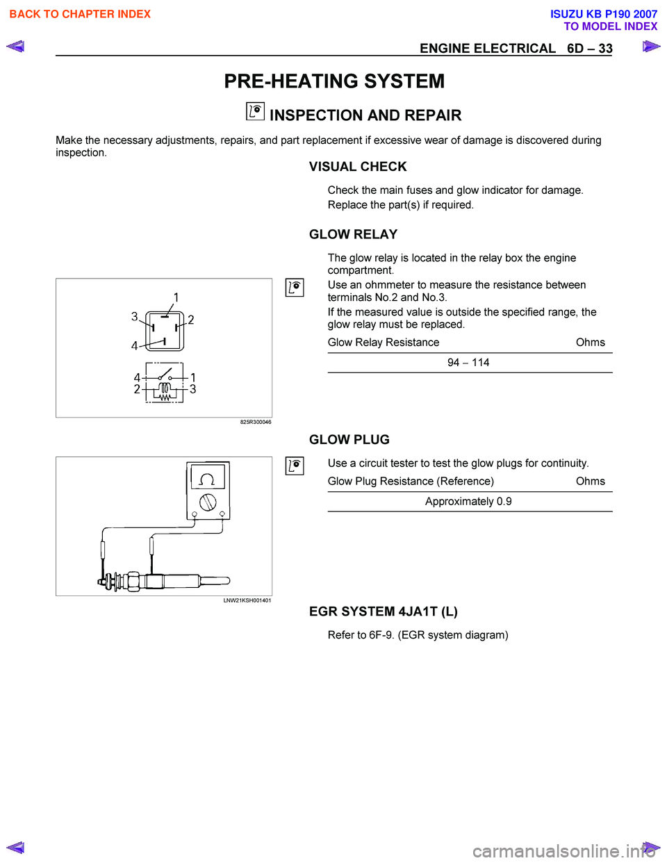
The glow relay is located in the relay box the engine
compartment.
825R300046
Use an ohmmeter to measure the resistance between
terminals No.2 and No.3.
If the measured value is outside the specified range, the
glow relay must be replaced.
Glow Relay Resistance Ohms
94 − 114
GLOW PLUG
LNW21KSH001401
Use a circuit tester to test the glow plugs for continuity.
Glow Plug Resistance (Reference) Ohms
Approximately 0.9
EGR SYSTEM 4JA1T (L)
Refer to 6F-9. (EGR system diagram)
BACK TO CHAPTER INDEX
TO MODEL INDEX
ISUZU KB P190 2007
Page 1052 of 6020
6E-18 Engine Control System (4JH1)
Component Locator
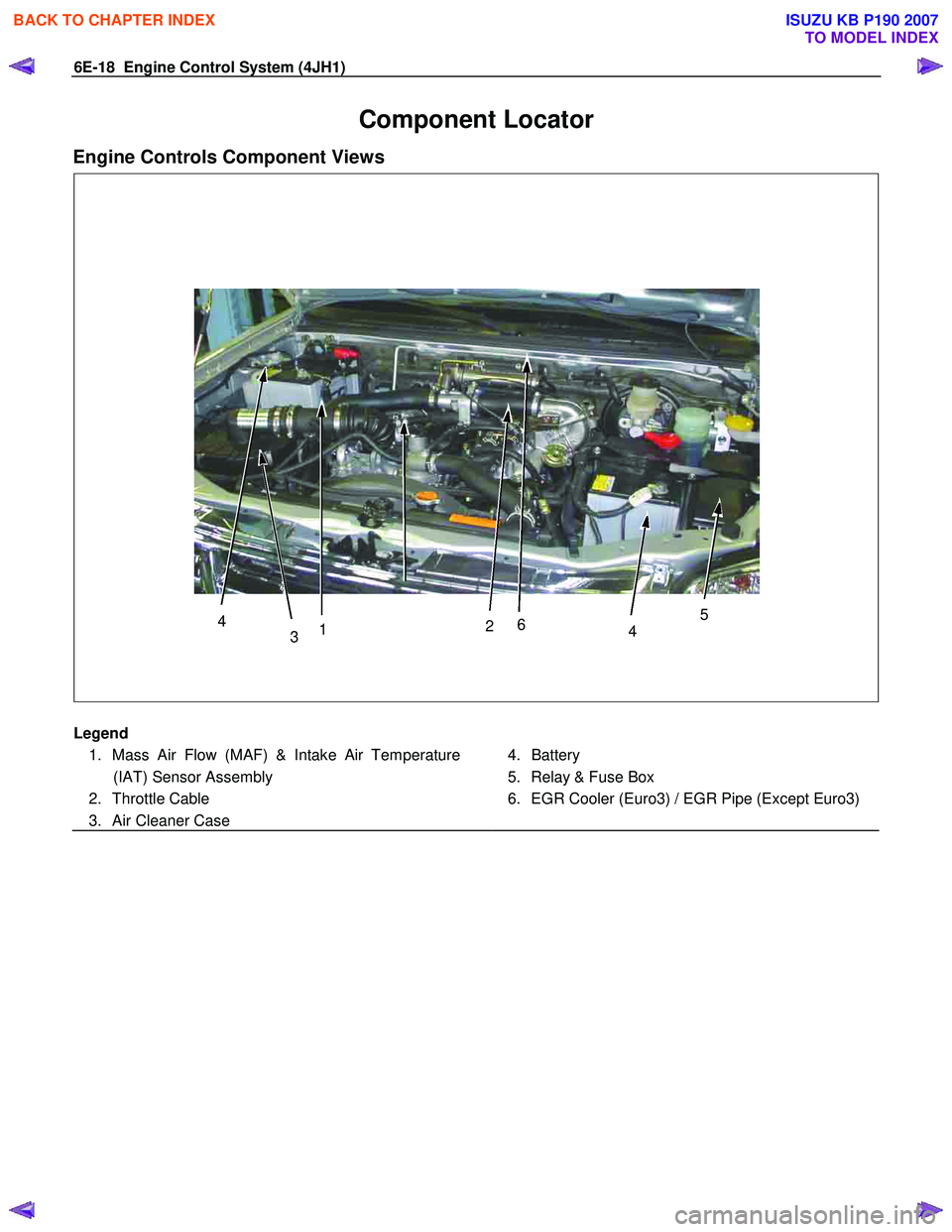
Engine Controls Component Views
3
4
1 2
6
45
Legend
1. Mass Air Flow (MAF) & Intake Air Temperature (IAT) Sensor Assembly
2. Throttle Cable
3. Air Cleaner Case
4. Battery
5. Relay & Fuse Box
6. EGR Cooler (Euro3) / EGR Pipe (Except Euro3)
BACK TO CHAPTER INDEX
TO MODEL INDEX
ISUZU KB P190 2007
Page 1056 of 6020
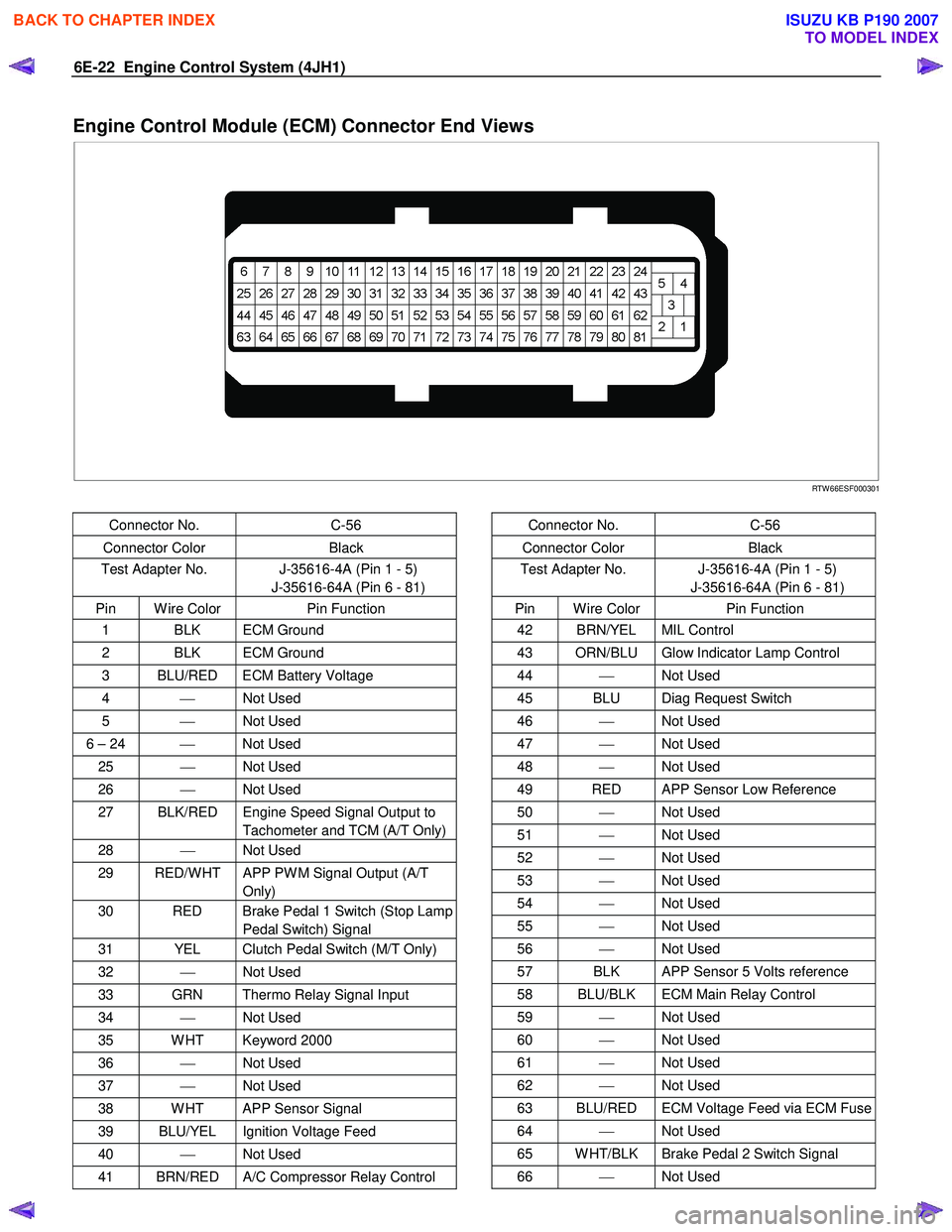
6E-22 Engine Control System (4JH1)
Engine Control Module (ECM) Connector End Views
RTW 66ESF000301
Connector No. C-56
Connector Color Black
Test Adapter No. J-35616-4A (Pin 1 - 5)
J-35616-64A (Pin 6 - 81)
Pin W ire Color Pin Function
1 BLK ECM Ground
2 BLK ECM Ground
3 BLU/RED ECM Battery Voltage
4 Not Used
5 Not Used
6 – 24 Not Used
25 Not Used
26 Not Used
27 BLK/RED Engine Speed Signal Output to
Tachometer and TCM (A/T Only)
28 Not Used
29 RED/W HT APP PW M Signal Output (A/T
Only)
30 RED Brake Pedal 1 Switch (Stop Lamp Pedal Switch) Signal
31 YEL Clutch Pedal Switch (M/T Only)
32 Not Used
33 GRN Thermo Relay Signal Input
34 Not Used
35 W HT Keyword 2000
36 Not Used
37 Not Used
38 W HT APP Sensor Signal
39 BLU/YEL Ignition Voltage Feed
40 Not Used
41 BRN/RED A/C Compressor Relay Control
Connector No. C-56
Connector Color Black
Test Adapter No. J-35616-4A (Pin 1 - 5)
J-35616-64A (Pin 6 - 81)
Pin W ire Color Pin Function
42 BRN/YEL MIL Control
43 ORN/BLU Glow Indicator Lamp Control
44 Not Used
45 BLU Diag Request Switch
46 Not Used
47 Not Used
48 Not Used
49 RED APP Sensor Low Reference
50 Not Used
51 Not Used
52 Not Used
53 Not Used
54 Not Used
55 Not Used
56 Not Used
57 BLK APP Sensor 5 Volts reference
58 BLU/BLK ECM Main Relay Control
59 Not Used
60 Not Used
61 Not Used
62 Not Used
63 BLU/RED ECM Voltage Feed via ECM Fuse
64 Not Used
65 W HT/BLK Brake Pedal 2 Switch Signal
66 Not Used
BACK TO CHAPTER INDEX
TO MODEL INDEX
ISUZU KB P190 2007
Page 1058 of 6020
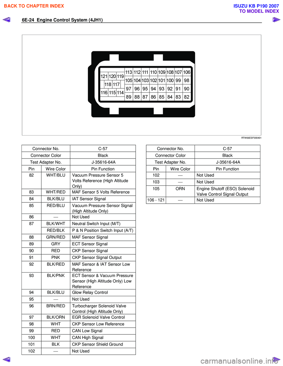
6E-24 Engine Control System (4JH1)
RTW 66ESF000401
Connector No. C-57
Connector Color Black
Test Adapter No. J-35616-64A
Pin W ire Color Pin Function
82 W HT/BLU Vacuum Pressure Sensor 5
Volts Reference (High Altitude
Only)
83 W HT/RED MAF Sensor 5 Volts Reference
84 BLK/BLU IAT Sensor Signal
85 RED/BLU Vacuum Pressure Sensor Signal (High Altitude Only)
86 Not Used
BLK/W HT Neutral Switch Input (M/T) 87
RED/BLK P & N Position Switch Input (A/T)
88 GRN/RED MAF Sensor Signal
89 GRY ECT Sensor Signal
90 RED CKP Sensor Signal
91 PNK CKP Sensor Signal Output
92 BLK/RED MAF Sensor & IAT Sensor Low Reference
93 BLK/PNK ECT Sensor & Vacuum Pressure Sensor (High Altitude Only) Low
Reference
94 BLK/BLU Glow Relay Control
95 Not Used
96 BRN/RED Turbocharger Solenoid Valve
Control (High Altitude Only)
97 BLK/ORN EGR Solenoid Valve Control
98 W HT CKP Sensor Low Reference
99 RED CAN Low Signal
100 W HT CAN High Signal
101 BLK CKP Sensor Shield Ground
102 Not Used
Connector No. C-57
Connector Color Black
Test Adapter No. J-35616-64A
Pin W ire Color Pin Function
102 Not Used
103 Not Used
105 ORN Engine Shutoff (ESO) Solenoid
Valve Control Signal Output
106 - 121 Not Used
BACK TO CHAPTER INDEX
TO MODEL INDEX
ISUZU KB P190 2007