2007 ISUZU KB P190 Circuit
[x] Cancel search: CircuitPage 2238 of 6020
6E–68 ENGINE DRIVEABILITY AND EMISSIONS
On-Board Diagnostic (OBD)
On-Board Diagnostic Tests
A diagnostic test is a series of steps, the result of which
is a pass or fail reported to the diagnostic executive.
When a diagnostic test reports a pass result, the
diagnostic executive records the following data:
• The diagnostic test has been completed since the last ignition cycle.
• The diagnostic test has passed during the current ignition cycle.
• The fault identified by the diagnostic test is not currently active.
When a diagnostic test reports a fail result, the
diagnostic executive records the following data:
• The diagnostic test has been completed since the last ignition cycle.
• The fault identified by the diagnostic test is currently active.
• The fault has been active during this ignition cycle.
• The operating conditions at the time of the failure.
The Diagnostic Executive
The Diagnostic Executive is a unique segment of
software which is designed to coordinate and prioritize
the diagnostic procedures as well as define the protocol
for recording and displaying their results. The main
responsibilities of the Diagnostic Executive are listed as
follows:
• Commanding the check engine lamp on and off
• DTC logging and clearing
• Current status information on each diagnostic
Diagnostic Information
The diagnostic charts and functional checks are
designed to locate a faulty circuit or component through
a process of logical decisions. The charts are prepared
with the requirement that the vehicle functioned
correctly at the time of assembly and that there are not
multiple faults present.
There is a continuous self-diagnosis on certain control
functions. This diagnostic capability is complemented
by the diagnostic procedures contained in this manual.
The language of communicating the source of the
malfunction is a system of diagnostic trouble codes.
When a malfunction is detected by the control module, a
diagnostic trouble code is set and the check engine
lamp is illuminated.
Check Engine Lamp
The check engine lamp looks the same as the check
engine lamp you are already familiar with, the “Check
Engine” lamp.
Basically, the check engine lamp is turned on when the
ECM detects a DTC that will impact the vehicle
emissions.
• When the check engine lamp remains “ON” while the engine is running, or when a malfunction is suspected due to a driveability or emissions problem,
a Powertrain On-Board Diagnostic (OBD) System
Check must be performed. The procedures for these
checks are given in On-Board Diagnostic (OBD)
System Check. These checks will expose faults
which may not be detected if other diagnostics are
performed first.
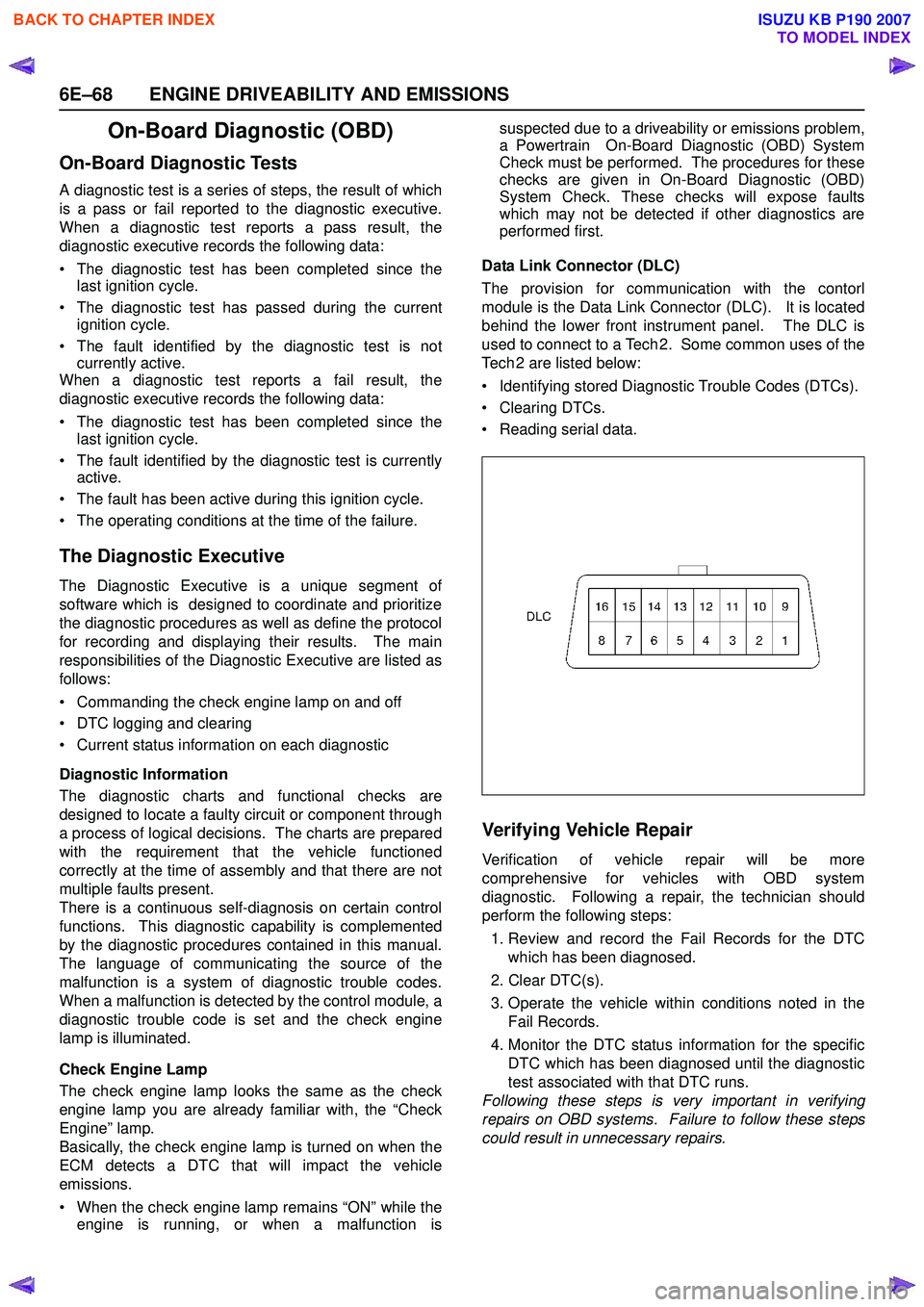
Data Link Connector (DLC)
The provision for communication with the contorl
module is the Data Link Connector (DLC). It is located
behind the lower front instrument panel. The DLC is
used to connect to a Tech 2. Some common uses of the
Tech 2 are listed below:
• Identifying stored Diagnostic Trouble Codes (DTCs).
• Clearing DTCs.
• Reading serial data.
Verifying Vehicle Repair
Verification of vehicle repair will be more
comprehensive for vehicles with OBD system
diagnostic. Following a repair, the technician should
perform the following steps:
1. Review and record the Fail Records for the DTC which has been diagnosed.
2. Clear DTC(s).
3. Operate the vehicle within conditions noted in the Fail Records.
4. Monitor the DTC status information for the specific DTC which has been diagnosed until the diagnostic
test associated with that DTC runs.
Following these steps is very important in verifying
repairs on OBD systems. Failure to follow these steps
could result in unnecessary repairs.
BACK TO CHAPTER INDEX
TO MODEL INDEX
ISUZU KB P190 2007
Page 2246 of 6020
6E–76 ENGINE DRIVEABILITY AND EMISSIONS
MISCELLANEOUS TEST
The state of each circuit can be tested by using
miscellaneous test menus. Especially when DTC
cannot be detected, a faulty circuit can be diagnosed by
testing each circuit by means of these menus.
Even DTC has been detected, the circuit tests using
these menus could help discriminate between a
mechanical trouble and an electrical trouble.
Connect Tech 2 and select “Powertrain”, “2.XL L4
HV240” & “Miscellaneous Test”.
F0: Lamps
F0: Malfunction Indicator Lamp
When the Tech 2 is operated, “Malfunction Indicator
Lamp (Check Engine Lamp)” is turned on or off.
The circuit is normal if the “Malfunction Indicator Lamp
(Check Engine Lamp)” in the instrument panel is turned
on or off in accordance with this operation.
F1: Relays
F0: Fuel Pump Relay
When the Tech 2 is operated, fuel pump relay signal
turns ON or OFF.
The circuit is normal if fuel pump sound is generated in
accordance with this operation when key switch is
turned ON.
F1: A/C Clutch Relay
When the Tech 2 is operated, A/C clutch relay signal
turns ON or OFF.
The circuit is normal if A/C compressor clutch is
energized in accordance with this operation when the
engine is running.
F2: EVAP
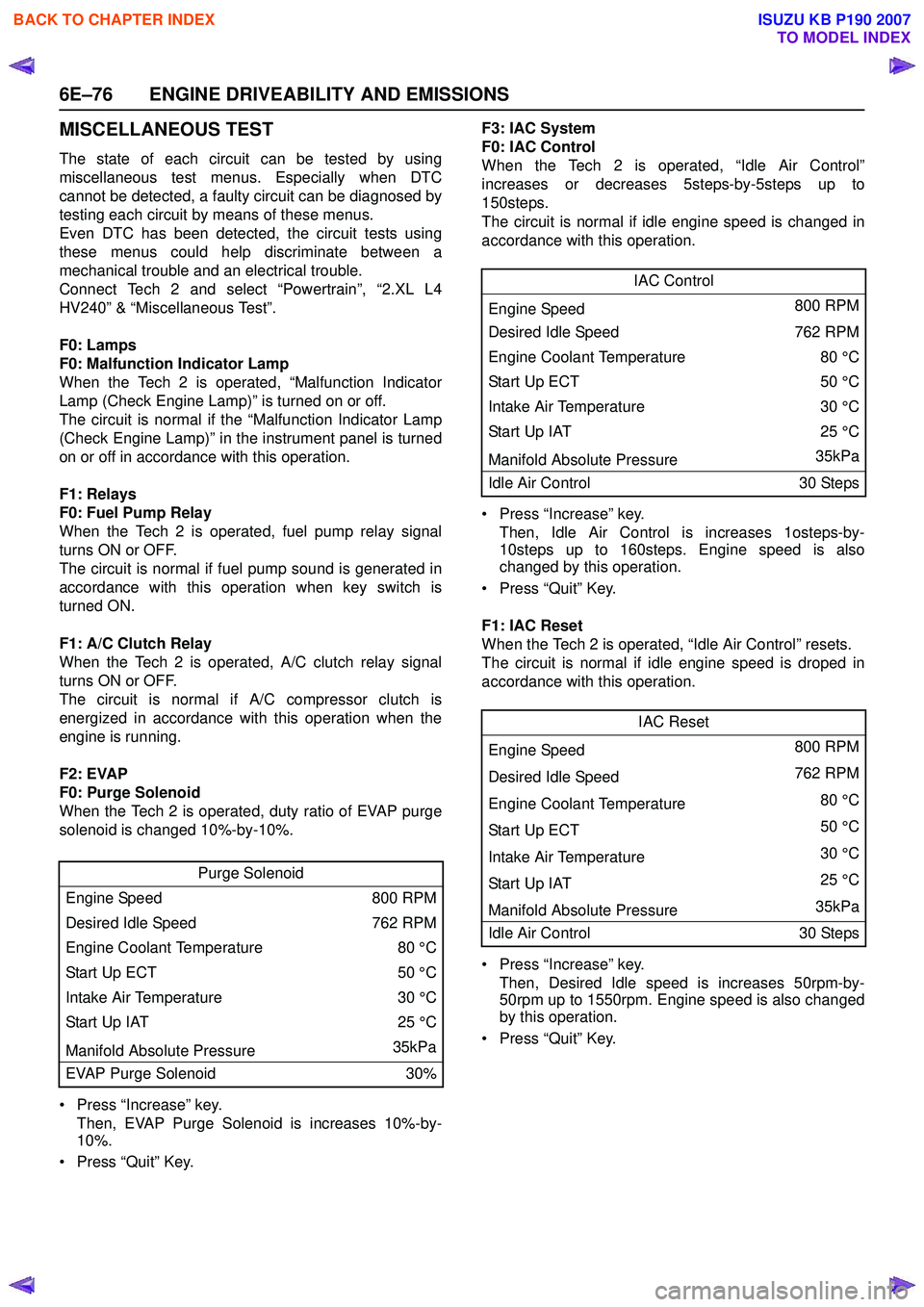
F0: Purge Solenoid
When the Tech 2 is operated, duty ratio of EVAP purge
solenoid is changed 10%-by-10%.
• Press “Increase” key. Then, EVAP Purge Solenoid is increases 10%-by-
10%.
• Press “Quit” Key. F3: IAC System
F0: IAC Control
When the Tech 2 is operated, “Idle Air Control”
increases or decreases 5steps-by-5steps up to
150steps.
The circuit is normal if idle engine speed is changed in
accordance with this operation.
• Press “Increase” key. Then, Idle Air Control is increases 1osteps-by-
10steps up to 160steps. Engine speed is also
changed by this operation.
• Press “Quit” Key.
F1: IAC Reset
When the Tech 2 is operated, “Idle Air Control” resets.
The circuit is normal if idle engine speed is droped in
accordance with this operation.
• Press “Increase” key. Then, Desired Idle speed is increases 50rpm-by-
50rpm up to 1550rpm. Engine speed is also changed
by this operation.
• Press “Quit” Key.
Purge Solenoid
Engine Speed 800 RPM
Desired Idle Speed 762 RPM
Engine Coolant Temperature 80 °C
Start Up ECT 50 °C
Intake Air Temperature 30 °C
Start Up IAT 25 °C
Manifold Absolute Pressure 35kPa
EVAP Purge Solenoid 30%
IAC Control
Engine Speed 800 RPM
Desired Idle Speed 762 RPM
Engine Coolant Temperature 80 °C
Sta rt U p E C T 50 °C
Intake Air Temperature 30 °C
Start Up IAT25 °C
Manifold Absolute Pressure 35kPa
Idle Air Control 30 Steps
IAC Reset
Engine Speed 800 RPM
Desired Idle Speed 762 RPM
Engine Coolant Temperature 80 °C
Sta rt U p E C T 50 °C
Intake Air Temperature 30 °C
Start Up IAT 25 °C
Manifold Absolute Pressure 35kPa
Idle Air Control 30 Steps
BACK TO CHAPTER INDEX
TO MODEL INDEX
ISUZU KB P190 2007
Page 2247 of 6020
ENGINE DRIVEABILITY AND EMISSIONS 6E–77
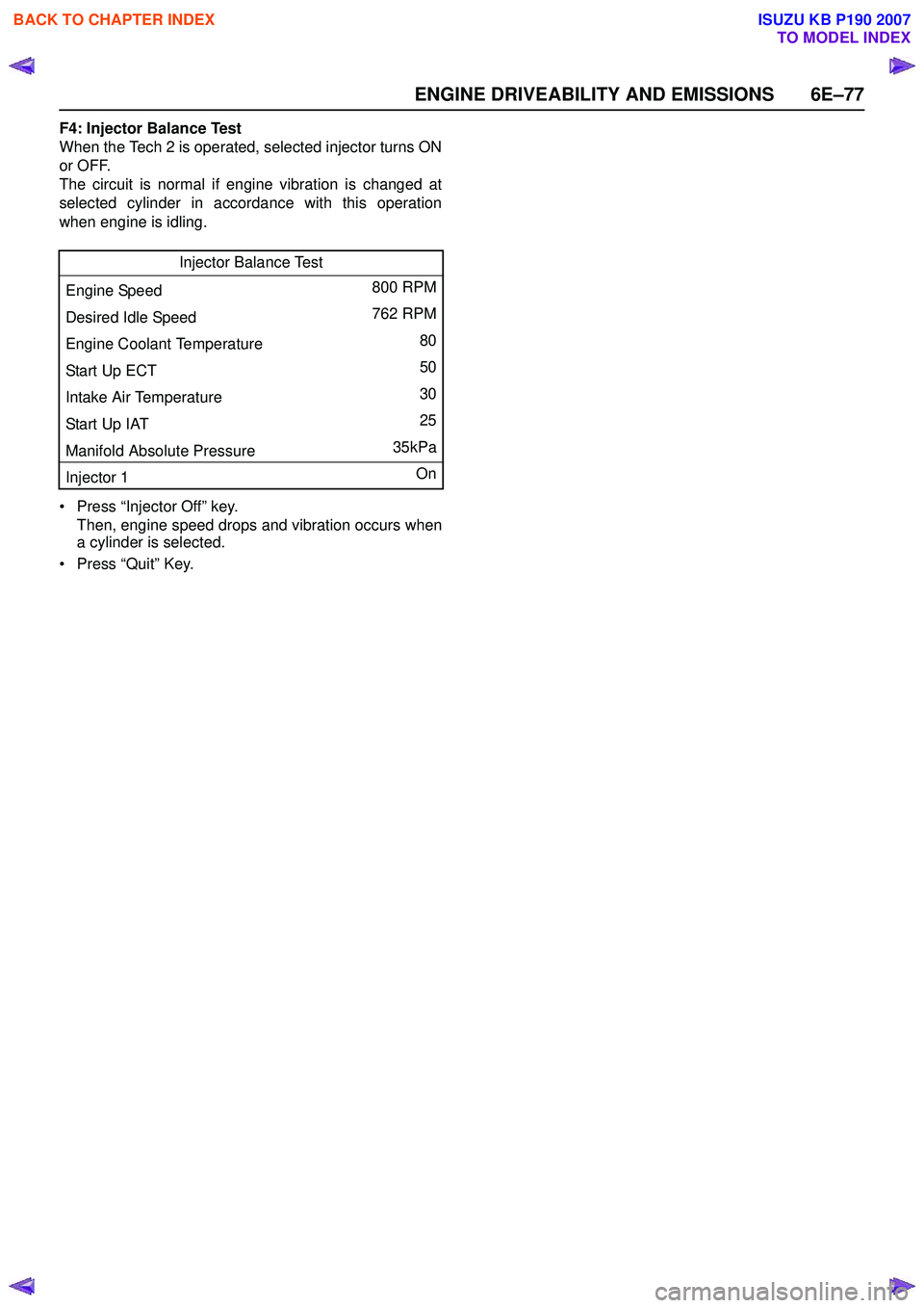
F4: Injector Balance Test
When the Tech 2 is operated, selected injector turns ON
or OFF.
The circuit is normal if engine vibration is changed at
selected cylinder in accordance with this operation
when engine is idling.
• Press “Injector Off” key. Then, engine speed drops and vibration occurs when
a cylinder is selected.
• Press “Quit” Key. Injector Balance Test
Engine Speed 800 RPM
Desired Idle Speed 762 RPM
Engine Coolant Temperature 80
Start Up ECT 50
Intake Air Temperature 30
Start Up IAT 25
Manifold Absolute Pressure 35kPa
Injector 1 On
BACK TO CHAPTER INDEX
TO MODEL INDEX
ISUZU KB P190 2007
Page 2258 of 6020
6E–88 ENGINE DRIVEABILITY AND EMISSIONS
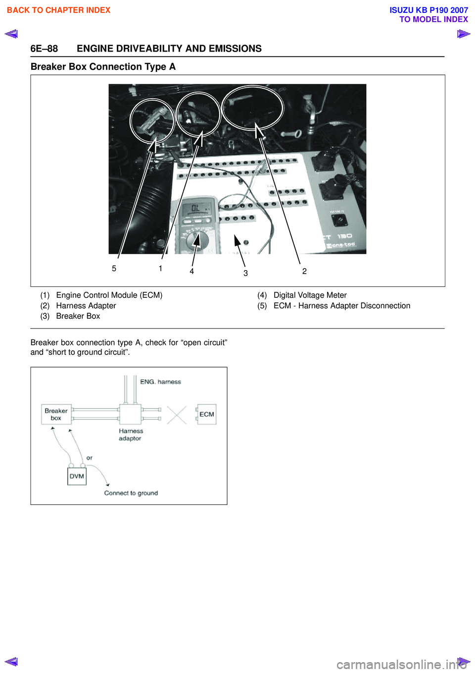
Breaker Box Connection Type A
Breaker box connection type A, check for “open circuit”
and “short to ground circuit”.
51 43 2
(1) Engine Control Module (ECM)
(2) Harness Adapter
(3) Breaker Box (4) Digital Voltage Meter
(5) ECM - Harness Adapter Disconnection
BACK TO CHAPTER INDEX
TO MODEL INDEX
ISUZU KB P190 2007
Page 2259 of 6020
ENGINE DRIVEABILITY AND EMISSIONS 6E–89
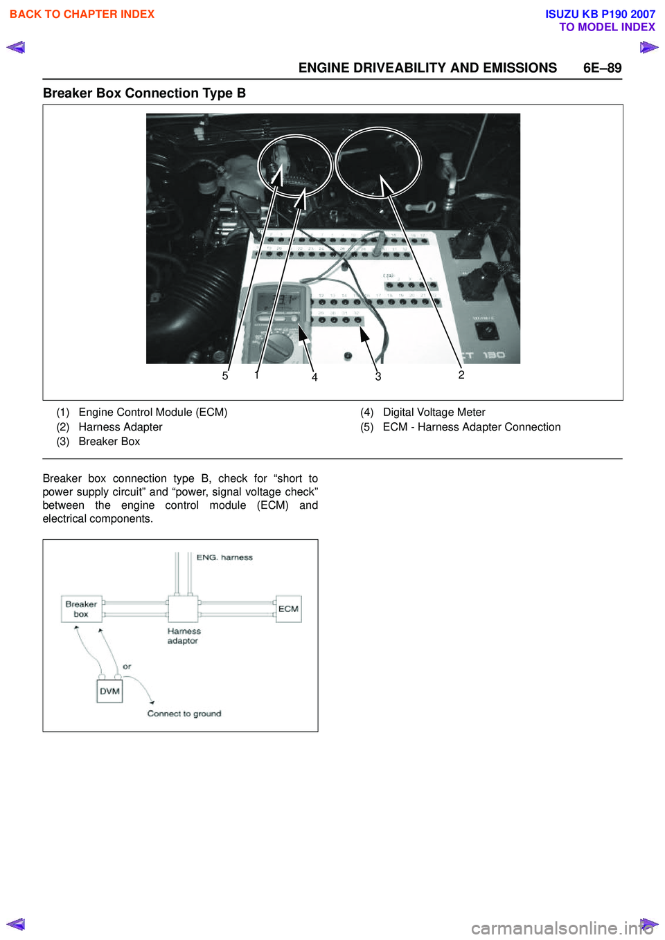
Breaker Box Connection Type B
Breaker box connection type B, check for “short to
power supply circuit” and “power, signal voltage check”
between the engine control module (ECM) and
electrical components.
5 1
4 3 2
(1) Engine Control Module (ECM)
(2) Harness Adapter
(3) Breaker Box (4) Digital Voltage Meter
(5) ECM - Harness Adapter Connection
BACK TO CHAPTER INDEX
TO MODEL INDEX
ISUZU KB P190 2007
Page 2260 of 6020
6E–90 ENGINE DRIVEABILITY AND EMISSIONS
ON-BOARD DIAGNOSTIC (OBD) SYSTEM CHECK
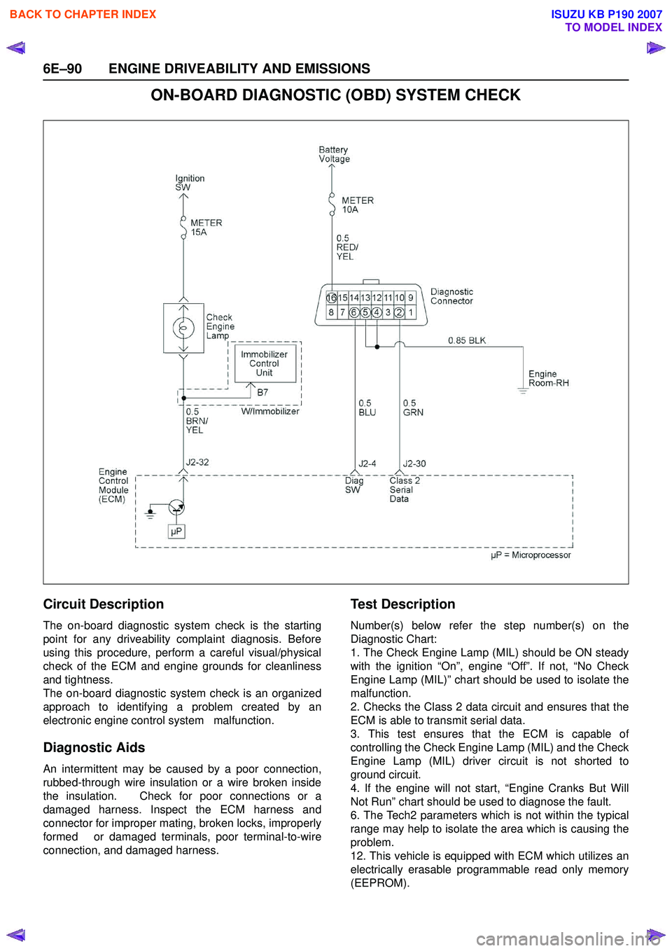
Circuit Description
The on-board diagnostic system check is the starting
point for any driveability complaint diagnosis. Before
using this procedure, perform a careful visual/physical
check of the ECM and engine grounds for cleanliness
and tightness.
The on-board diagnostic system check is an organized
approach to identifying a problem created by an
electronic engine control system malfunction.
Diagnostic Aids
An intermittent may be caused by a poor connection,
rubbed-through wire insulation or a wire broken inside
the insulation. Check for poor connections or a
damaged harness. Inspect the ECM harness and
connector for improper mating, broken locks, improperly
formed or damaged terminals, poor terminal-to-wire
connection, and damaged harness.
Te s t D e s c r i p t i o n
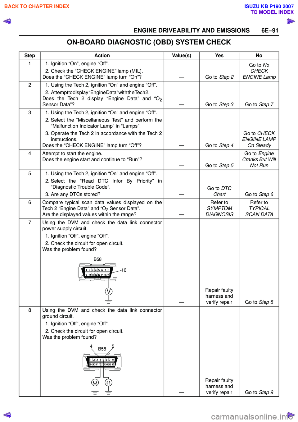
Number(s) below refer the step number(s) on the
Diagnostic Chart:
1. The Check Engine Lamp (MIL) should be ON steady
with the ignition “On”, engine “Off”. If not, “No Check
Engine Lamp (MIL)” chart should be used to isolate the
malfunction.
2. Checks the Class 2 data circuit and ensures that the
ECM is able to transmit serial data.
3. This test ensures that the ECM is capable of
controlling the Check Engine Lamp (MIL) and the Check
Engine Lamp (MIL) driver circuit is not shorted to
ground circuit.
4. If the engine will not start, “Engine Cranks But Will
Not Run” chart should be used to diagnose the fault.
6. The Tech2 parameters which is not within the typical
range may help to isolate the area which is causing the
problem.
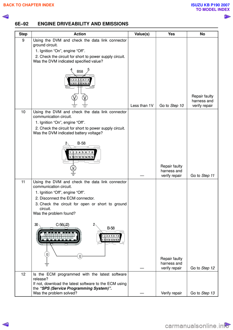
12. This vehicle is equipped with ECM which utilizes an
electrically erasable programmable read only memory
(EEPROM).
BACK TO CHAPTER INDEX
TO MODEL INDEX
ISUZU KB P190 2007
Page 2261 of 6020
ENGINE DRIVEABILITY AND EMISSIONS 6E–91
ON-BOARD DIAGNOSTIC (OBD) SYSTEM CHECK
StepAction Value(s) Yes No
1 1. Ignition “On”, engine “Off”. 2. Check the “CHECK ENGINE” lamp (MIL).
Does the “CHECK ENGINE” lamp turn “On”? — Go to Step 2Go to
No
CHECK
ENGINE Lamp
2 1. Using the Tech 2, ignition “On” and engine “Off”. 2 . A t t e m p t t o d i s p l a y “ E n g i n e D a t a ” w i t h t h e T e c h 2 .
Does the Tech 2 display “Engine Data” and “O
2Sensor Data”? — Go to Step 3Go to Step 7
3 1. Using the Tech 2, ignition “On” and engine “Off”. 2. Select the “Miscellaneous Test” and perform the“Malfunction Indicator Lamp” in “Lamps”.
3. Operate the Tech 2 in accordance with the Tech 2 instructions.
Does the “CHECK ENGINE” lamp turn “Off”? — Go to Step 4Go to
CHECK
ENGINE LAMP On Steady
4 Attempt to start the engine. Does the engine start and continue to “Run”? —Go to Step 5Go to
Engine
Cranks But Will Not Run
5 1. Using the Tech 2, ignition “On” and engine “Off”. 2. Select the “Read DTC Infor By Priority” in“Diagnostic Trouble Code”.
3. Are any DTCs stored? —Go to
DTC
Chart Go to Step 6
6 Compare typical scan data values displayed on the Tech 2 “Engine Data” and “O
2 Sensor Data”.
Are the displayed values within the range? —Refer to
SYMPTOM
DIAGNOSIS Refer to
TYPICAL
SCAN DATA
7 Using the DVM and check the data link connector power supply circuit.
1. Ignition “Off”, engine “Off”.
2. Check the circuit for open circuit.
Was the problem found?
—Repair faulty
harness and verify repair Go to Step 8
8 Using the DVM and check the data link connector ground circuit.
1. Ignition “Off”, engine “Off”.
2. Check the circuit for open circuit.
Was the problem found?
—Repair faulty
harness and verify repair Go to Step 9
V
16
B58
5
4B58
BACK TO CHAPTER INDEX
TO MODEL INDEX
ISUZU KB P190 2007
Page 2262 of 6020
6E–92 ENGINE DRIVEABILITY AND EMISSIONS
9 Using the DVM and check the data link connectorground circuit.
1. Ignition “On”, engine “Off”.
2. Check the circuit for short to power supply circuit.
Was the DVM indicated specified value?
Less than 1V Go to Step 10Repair faulty
harness and verify repair
10 Using the DVM and check the data link connector communication circuit.
1. Ignition “On”, engine “Off”.
2. Check the circuit for short to power supply circuit.
Was the DVM indicated battery voltage?
—Repair faulty
harness and verify repair Go to Step 11
11 Using the DVM and check the data link connector communication circuit.
1. Ignition “Off”, engine “Off”.
2. Disconnect the ECM connector.
3. Check the circuit for open or short to ground circuit.
Was the problem found?
—Repair faulty
harness and verify repair Go to Step 12
12 Is the ECM programmed with the latest software release?
If not, download the latest software to the ECM using
the “SPS (Service Programming System)”.
Was the problem solved? — Verify repair Go to Step 13
Step
Action Value(s) Yes No
VV
5
4B58
V
B-582
C-56(J2)
ΩΩ
B-58230
BACK TO CHAPTER INDEX
TO MODEL INDEX
ISUZU KB P190 2007