2007 ISUZU KB P190 check engine
[x] Cancel search: check enginePage 2198 of 6020
6E–28 ENGINE DRIVEABILITY AND EMISSIONS
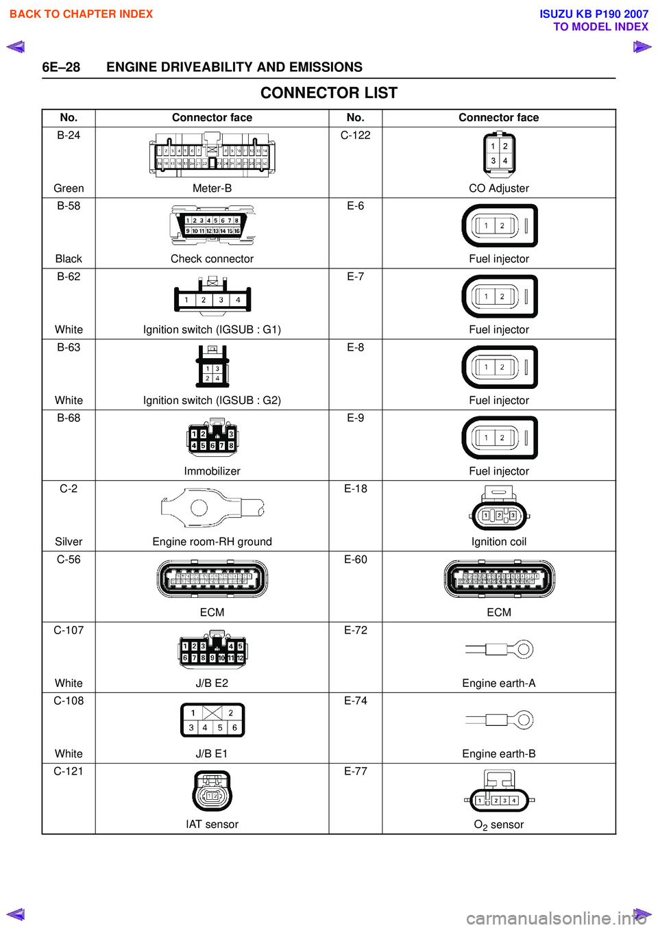
CONNECTOR LIST
No.Connector face No.Connector face
B-24
Green Meter-B C-122
CO Adjuster
B-58
Black Check connector E-6
Fuel injector
B-62
White Ignition switch (IGSUB : G1) E-7
Fuel injector
B-63
White Ignition switch (IGSUB : G2) E-8
Fuel injector
B-68
Immobilizer E-9
Fuel injector
C-2
Silver Engine room-RH ground E-18
Ignition coil
C-56
ECM E-60
ECM
C-107
White J/B E2 E-72
Engine earth-A
C-108
White J/B E1 E-74
Engine earth-B
C-121
IAT sensor E-77
O
2 sensor
BACK TO CHAPTER INDEX
TO MODEL INDEX
ISUZU KB P190 2007
Page 2215 of 6020
ENGINE DRIVEABILITY AND EMISSIONS 6E–45
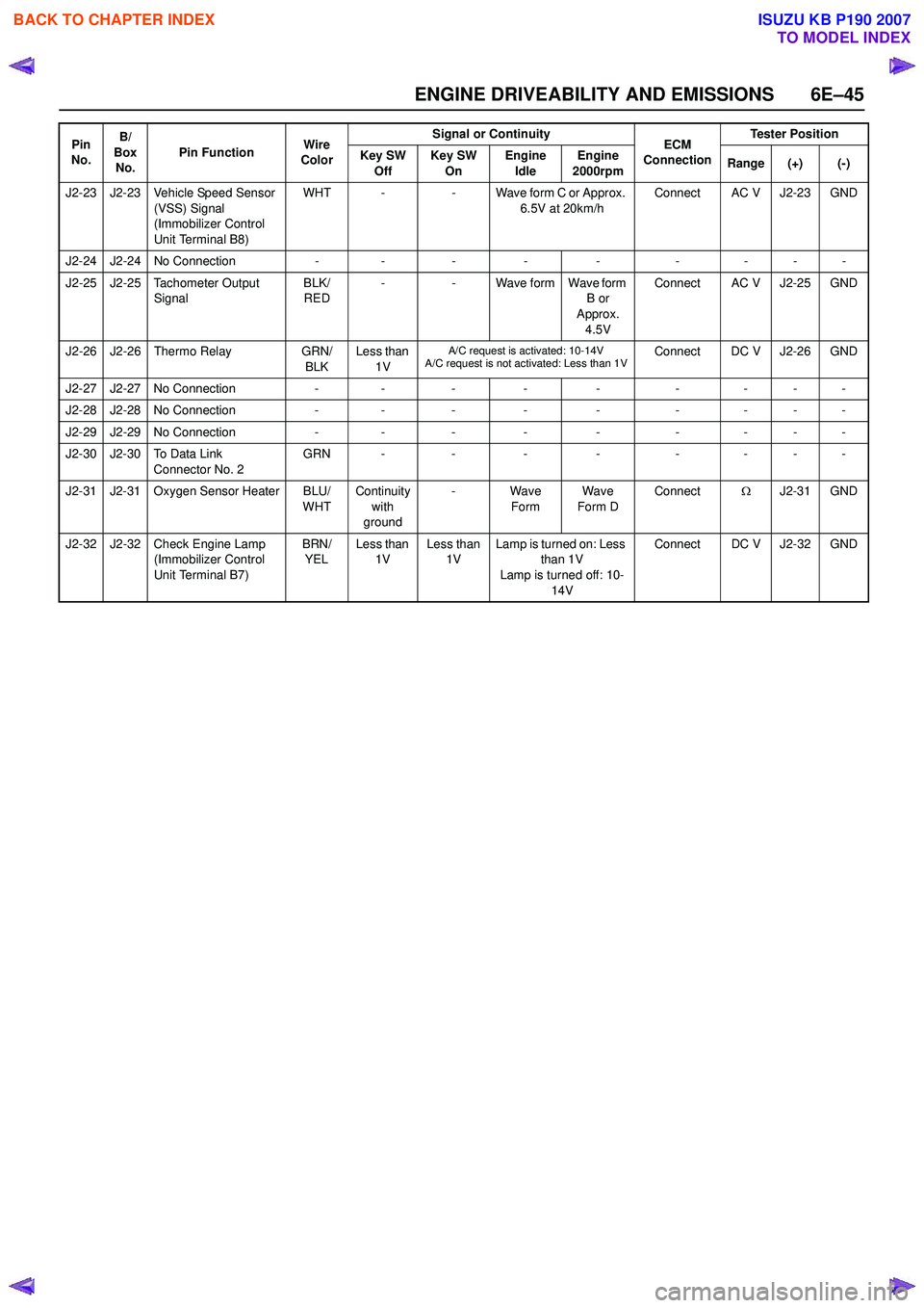
J2-23 J2-23 Vehicle Speed Sensor (VSS) Signal
(Immobilizer Control
Unit Terminal B8) WHT -
- Wave form C or Approx.
6.5V at 20km/h Connect AC V J2-23 GND
J2-24 J2-24 No Connection -- - - - -- - -
J2-25 J2-25 Tachometer Output Signal BLK/
RED -
- Wave form Wave form
B or
Approx.
4.5V Connect AC V J2-25 GND
J2-26 J2-26 Thermo Relay GRN/
BLK Less than
1V
A/C request is activated: 10-14V
A/C request is not activated: Less than 1VConnect DC V J2-26 GND
J2-27 J2-27 No Connection - - - - - - - - -
J2-28 J2-28 No Connection - - - - - - - - -
J2-29 J2-29 No Connection -- - - - -- - -
J2-30 J2-30 To Data Link Connector No. 2 GRN -
-- - -- - -
J2-31 J2-31 Oxygen Sensor Heater BLU/ WHTContinuity
with
ground - Wave
Form Wave
Form D Connect
ΩJ2-31 GND
J2-32 J2-32 Check Engine Lamp (Immobilizer Control
Unit Terminal B7) BRN/
YEL Less than
1V Less than
1V Lamp is turned on: Less
than 1V
Lamp is turned off: 10-
14V Connect DC V J2-32 GND
Pin
No. B/
Box No. Pin Function
Wire
Color Signal or Continuity
ECM
Connection Tester Position
Key SW Off Key SW
On Engine
Idle Engine
2000rpm Range (+) (-)
BACK TO CHAPTER INDEX
TO MODEL INDEX
ISUZU KB P190 2007
Page 2218 of 6020
6E–48 ENGINE DRIVEABILITY AND EMISSIONS
GENERAL DESCRIPTION FOR ECM AND
SENSORS
Engine Control Module (ECM)
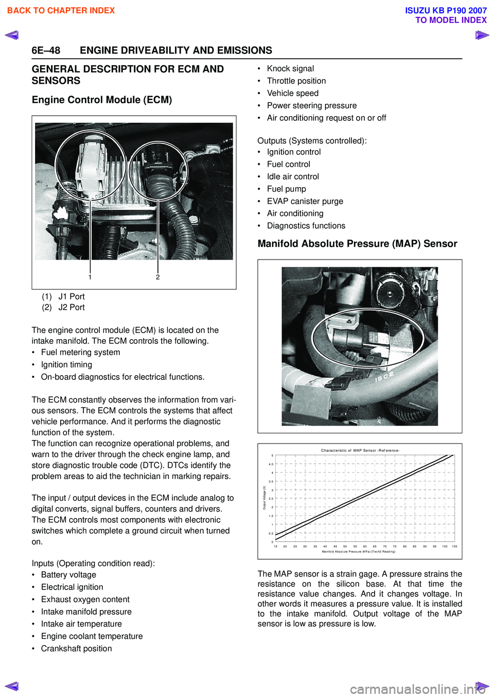
The engine control module (ECM) is located on the
intake manifold. The ECM controls the following.
• Fuel metering system
• Ignition timing
• On-board diagnostics for electrical functions.
The ECM constantly observes the information from vari-
ous sensors. The ECM controls the systems that affect
vehicle performance. And it performs the diagnostic
function of the system.
The function can recognize operational problems, and
warn to the driver through the check engine lamp, and
store diagnostic trouble code (DTC). DTCs identify the
problem areas to aid the technician in marking repairs.
The input / output devices in the ECM include analog to
digital converts, signal buffers, counters and drivers.
The ECM controls most components with electronic
switches which complete a ground circuit when turned
on.
Inputs (Operating condition read):
• Battery voltage
• Electrical ignition
• Exhaust oxygen content
• Intake manifold pressure
• Intake air temperature
• Engine coolant temperature
• Crankshaft position • Knock signal
• Throttle position
• Vehicle speed
• Power steering pressure
• Air conditioning request on or off
Outputs (Systems controlled):
• Ignition control
• Fuel control
• Idle air control
• Fuel pump
• EVAP canister purge
• Air conditioning
• Diagnostics functions
Manifold Absolute Pressure (MAP) Sensor
The MAP sensor is a strain gage. A pressure strains the
resistance on the silicon base. At that time the
resistance value changes. And it changes voltage. In
other words it measures a pressure value. It is installed
to the intake manifold. Output voltage of the MAP
sensor is low as pressure is low.
(1) J1 Port
(2) J2 Port
12
C harac t eris t ic of MAP Sens or -R ef erenc e-
0
0.5 1
1.5 2
2.5
3
3.5 4
4.5 5
15 20 25 30 35 40 45 50 55 60 65 70 75 80 85 90 95 100 105 Manifold Abs olute Press ure (KPa) (T ec h2 Reading)
Output Voltage (V)
BACK TO CHAPTER INDEX
TO MODEL INDEX
ISUZU KB P190 2007
Page 2222 of 6020
6E–52 ENGINE DRIVEABILITY AND EMISSIONS
GENERAL DESCRIPTION FOR FUEL
METERING
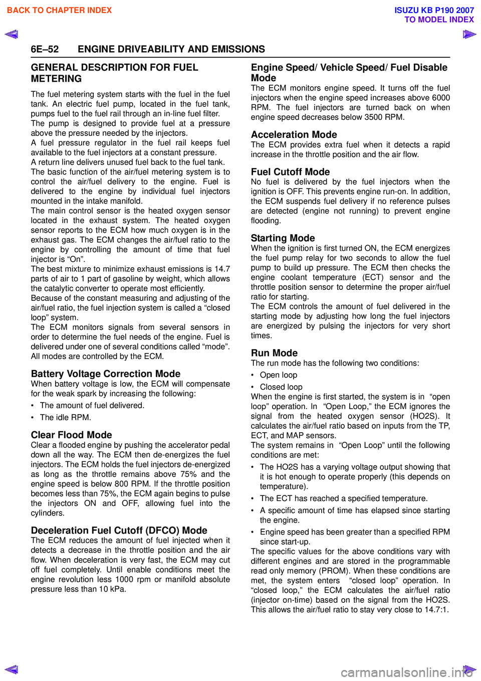
The fuel metering system starts with the fuel in the fuel
tank. An electric fuel pump, located in the fuel tank,
pumps fuel to the fuel rail through an in-line fuel filter.
The pump is designed to provide fuel at a pressure
above the pressure needed by the injectors.
A fuel pressure regulator in the fuel rail keeps fuel
available to the fuel injectors at a constant pressure.
A return line delivers unused fuel back to the fuel tank.
The basic function of the air/fuel metering system is to
control the air/fuel delivery to the engine. Fuel is
delivered to the engine by individual fuel injectors
mounted in the intake manifold.
The main control sensor is the heated oxygen sensor
located in the exhaust system. The heated oxygen
sensor reports to the ECM how much oxygen is in the
exhaust gas. The ECM changes the air/fuel ratio to the
engine by controlling the amount of time that fuel
injector is “On”.
The best mixture to minimize exhaust emissions is 14.7
parts of air to 1 part of gasoline by weight, which allows
the catalytic converter to operate most efficiently.
Because of the constant measuring and adjusting of the
air/fuel ratio, the fuel injection system is called a “closed
loop” system.
The ECM monitors signals from several sensors in
order to determine the fuel needs of the engine. Fuel is
delivered under one of several conditions called “mode”.
All modes are controlled by the ECM.
Battery Voltage Correction Mode
When battery voltage is low, the ECM will compensate
for the weak spark by increasing the following:
• The amount of fuel delivered.
• The idle RPM.
Clear Flood Mode
Clear a flooded engine by pushing the accelerator pedal
down all the way. The ECM then de-energizes the fuel
injectors. The ECM holds the fuel injectors de-energized
as long as the throttle remains above 75% and the
engine speed is below 800 RPM. If the throttle position
becomes less than 75%, the ECM again begins to pulse
the injectors ON and OFF, allowing fuel into the
cylinders.
Deceleration Fuel Cutoff (DFCO) Mode
The ECM reduces the amount of fuel injected when it
detects a decrease in the throttle position and the air
flow. When deceleration is very fast, the ECM may cut
off fuel completely. Until enable conditions meet the
engine revolution less 1000 rpm or manifold absolute
pressure less than 10 kPa.
Engine Speed/ Vehicle Speed/ Fuel Disable
Mode
The ECM monitors engine speed. It turns off the fuel
injectors when the engine speed increases above 6000
RPM. The fuel injectors are turned back on when
engine speed decreases below 3500 RPM.
Acceleration Mode
The ECM provides extra fuel when it detects a rapid
increase in the throttle position and the air flow.
Fuel Cutoff Mode
No fuel is delivered by the fuel injectors when the
ignition is OFF. This prevents engine run-on. In addition,
the ECM suspends fuel delivery if no reference pulses
are detected (engine not running) to prevent engine
flooding.
Starting Mode
When the ignition is first turned ON, the ECM energizes
the fuel pump relay for two seconds to allow the fuel
pump to build up pressure. The ECM then checks the
engine coolant temperature (ECT) sensor and the
throttle position sensor to determine the proper air/fuel
ratio for starting.
The ECM controls the amount of fuel delivered in the
starting mode by adjusting how long the fuel injectors
are energized by pulsing the injectors for very short
times.
Run Mode
The run mode has the following two conditions:
• Open loop
• Closed loop
When the engine is first started, the system is in “open
loop” operation. In “Open Loop,” the ECM ignores the
signal from the heated oxygen sensor (HO2S). It
calculates the air/fuel ratio based on inputs from the TP,
ECT, and MAP sensors.
The system remains in “Open Loop” until the following
conditions are met:
• The HO2S has a varying voltage output showing that it is hot enough to operate properly (this depends on
temperature).
• The ECT has reached a specified temperature.
• A specific amount of time has elapsed since starting the engine.
• Engine speed has been greater than a specified RPM since start-up.
The specific values for the above conditions vary with
different engines and are stored in the programmable
read only memory (PROM). When these conditions are
met, the system enters “closed loop” operation. In
“closed loop,” the ECM calculates the air/fuel ratio
(injector on-time) based on the signal from the HO2S.
This allows the air/fuel ratio to stay very close to 14.7:1.
BACK TO CHAPTER INDEX
TO MODEL INDEX
ISUZU KB P190 2007
Page 2224 of 6020
6E–54 ENGINE DRIVEABILITY AND EMISSIONS
GENERAL DESCRIPTION FOR ELECTRIC
IGNITION SYSTEM
The engine use two ignition coils, one per two cylinders.
A two wire connector provides a battery voltage primary
supply through the ignition fuse.
The ignition control spark timing is the ECM’s method of
controlling the spark advance and the ignition dwell.
The ignition control spark advance and the ignition dwell
are calculated by the ECM using the following inputs.
• Engine speed
• Crankshaft position (CKP) sensor
• Engine coolant temperature (ECT) sensor
• Throttle position sensor
• Vehicle speed sensor
• ECM and ignition system supply voltage
Ignition coil works to generate only the secondary
voltage be receiving the primary voltage from ECM.
The primary voltage is generated at the coil driver
located in the ECM. The coil driver generate the primary
voltage based on the crankshaft position signal. In
accordance with the crankshaft position signal, ignition
coil driver determines the adequate ignition timing and
also cylinder number to ignite.
Ignition timing is determined the coolant temperature,
intake air temperature, engine speed, engine load,
knock sensor signal, etc.
Spark Plug
Although worn or dirty spark plugs may give satisfactory
operation at idling speed, they frequently fail at higher
engine speeds. Faulty spark plugs may cause poor fuel
economy, power loss, loss of speed, hard starting and
generally poor engine performance. Follow the
scheduled maintenance service recommendations to
ensure satisfactory spark plug performance. Refer to
Maintenance and Lubrication .
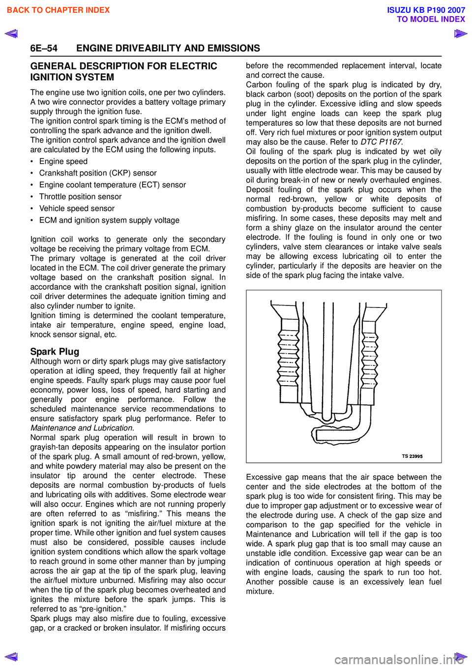
Normal spark plug operation will result in brown to
grayish-tan deposits appearing on the insulator portion
of the spark plug. A small amount of red-brown, yellow,
and white powdery material may also be present on the
insulator tip around the center electrode. These
deposits are normal combustion by-products of fuels
and lubricating oils with additives. Some electrode wear
will also occur. Engines which are not running properly
are often referred to as “misfiring.” This means the
ignition spark is not igniting the air/fuel mixture at the
proper time. While other ignition and fuel system causes
must also be considered, possible causes include
ignition system conditions which allow the spark voltage
to reach ground in some other manner than by jumping
across the air gap at the tip of the spark plug, leaving
the air/fuel mixture unburned. Misfiring may also occur
when the tip of the spark plug becomes overheated and
ignites the mixture before the spark jumps. This is
referred to as “pre-ignition.”
Spark plugs may also misfire due to fouling, excessive
gap, or a cracked or broken insulator. If misfiring occurs before the recommended replacement interval, locate
and correct the cause.
Carbon fouling of the spark plug is indicated by dry,
black carbon (soot) deposits on the portion of the spark
plug in the cylinder. Excessive idling and slow speeds
under light engine loads can keep the spark plug
temperatures so low that these deposits are not burned
off. Very rich fuel mixtures or poor ignition system output
may also be the cause. Refer to DTC P1167.
Oil fouling of the spark plug is indicated by wet oily
deposits on the portion of the spark plug in the cylinder,
usually with little electrode wear. This may be caused by
oil during break-in of new or newly overhauled engines.
Deposit fouling of the spark plug occurs when the
normal red-brown, yellow or white deposits of
combustion by-products become sufficient to cause
misfiring. In some cases, these deposits may melt and
form a shiny glaze on the insulator around the center
electrode. If the fouling is found in only one or two
cylinders, valve stem clearances or intake valve seals
may be allowing excess lubricating oil to enter the
cylinder, particularly if the deposits are heavier on the
side of the spark plug facing the intake valve.
Excessive gap means that the air space between the
center and the side electrodes at the bottom of the
spark plug is too wide for consistent firing. This may be
due to improper gap adjustment or to excessive wear of
the electrode during use. A check of the gap size and
comparison to the gap specified for the vehicle in
Maintenance and Lubrication will tell if the gap is too
wide. A spark plug gap that is too small may cause an
unstable idle condition. Excessive gap wear can be an
indication of continuous operation at high speeds or
with engine loads, causing the spark to run too hot.
Another possible cause is an excessively lean fuel
mixture.
BACK TO CHAPTER INDEX
TO MODEL INDEX
ISUZU KB P190 2007
Page 2228 of 6020
6E–58 ENGINE DRIVEABILITY AND EMISSIONS
• Damaged EVAP canister
• Leaking fuel sender assembly O-ring
• Leaking fuel tank or fuel filler neck
The ECM supplies a ground to energize the purge
control solenoid valve (purge “ON” ). The EVAP purge
control is turned “ON” and “OFF,” several times a
second. The duty cycle (pulse width) is determined by
engine operating conditions including load, throttle
position, coolant temperature and ambient temperature.
The duty cycle is calculated by the ECM and the output
is commanded when the appropriate conditions have
been met.
The system checks for conditions that cause the EVAP
system to purge continuously by commanding the EVAP
purge solenoid “OFF”, EVAP purge solenoid duty ratio
“0%”. If fuel tank vacuum level increases during the test,
a continuous purge flow condition is indicated. This can
be caused by the following conditions:
• EVAP purge solenoid leaking
• EVAP purge and engine vacuum lines switched at the EVAP purge control solenoid valve
• EVAP purge control solenoid valve driver circuit grounded
BACK TO CHAPTER INDEX
TO MODEL INDEX
ISUZU KB P190 2007
Page 2232 of 6020
6E–62 ENGINE DRIVEABILITY AND EMISSIONS
Diagnostic Thought Process
As you follow a diagnostic plan, every box on the
Strategy Based Diagnostics chart requires you to use
the diagnostic thought process. This method of thinking
optimizes your diagnosis in the following ways:
• Improves your understanding and definition of the customer complaint
• Saves time by avoiding testing and/or replacing good parts
• Allows you to look at the problem from different perspectives
• Guides you to determine what level of understanding about system operation is needed:
– Owner’s manual level
– Service manual level
– In-depth (engineering) level – Owner’s manual level
– Service manual level
– In-depth (engineering) level
1. Verify the Complaint
What you should do
To verify the customer complaint, you need to know the
correct (normal) operating behavior of the system and
verify that the customer complaint is a valid failure of the
system.
The following information will help you verify the
complaint:
• WHAT the vehicle model/options are
• WHAT aftermarket and dealer-installed accessories exist
• WHAT related system(s) operate properly
• WHEN the problem occurs
• WHERE the problem occurs
• HOW the problem occurs
• HOW LONG the condition has existed (and if the system ever worked correctly)
• HOW OFTEN the problem occurs
• Whether the severity of the problem has increased, decreased or stayed the same
What resources you should use
Whenever possible, you should use the following
resources to assist you in verifying the complaint:
• Service manual Theory or Circuit Description sections
• Service manual “System Performance Check”
• Owner manual operational description
• Technician experience
• Identical vehicle for comparison • Circuit testing tools
• Vehicle road tests
• Complaint check sheet
• Contact with the customer
2. Perform Preliminary Checks
NOTE: An estimated 10 percent of successful vehicle
repairs are diagnosed with this step!
What you should do
You perform preliminary checks for several reasons:
• To detect if the cause of the complaint is VISUALLY OBVIOUS
• To identify parts of the system that work correctly
• To accumulate enough data to correctly and accurately search for a ISUZU Service Bulletin on
ISUZU Web site.
The initial checks may vary depending on the
complexity of the system and may include the following
actions:
• Operate the suspect system
• Make a visual inspection of harness routing and accessible/visible power and ground circuits
• Check for blown fuses
• Make a visual inspection for separated connectors
• Make a visual inspection of connectors (includes checking terminals for damage and tightness)
• Check for any DTCs stored by the on-board computers
• Sense unusual noises, smells, vibrations or movements
• Investigate the vehicle service history (call other dealerships, if appropriate)
What resources you should use
Whenever appropriate, you should use the following
resources for assistance in performing preliminary
checks:
• Tech II or other technical equipment for viewing DTCs
• Service manual information: – Component locations
– Harness routing
– Wiring schematics
– Procedures for viewing DTCs
• Dealership service history file
• Vehicle road test
• Identical vehicle or system for comparison
BACK TO CHAPTER INDEX
TO MODEL INDEX
ISUZU KB P190 2007
Page 2233 of 6020
ENGINE DRIVEABILITY AND EMISSIONS 6E–63
3. Check Bulletins and Troubleshooting Hints
NOTE: As estimated 30 percent of successful vehicle
repairs are diagnosed with this step!
What you should do
You should have enough information gained from
preliminary checks to accurately search for a bulletin
and other related service information. Some service
manual sections provide troubleshooting hints that
match symptoms with specific complaints.
What resources you should use
You should use the following resources for assistance in
checking for bulletins and troubleshooting hints:
• Printed bulletins
• Access ISUZU Bulletin Web site.
• Videotapes
• Service manual
4. Perform Service Manual Diagnostic Checks
What you should do
The “System Checks” in most service manual sections
and in most cells of section 8A (electrical) provide you
with:
• A systematic approach to narrowing down the possible causes of a system fault
• Direction to specific diagnostic procedures in the service manual
• Assistance to identify what systems work correctly
What resources you should use
Whenever possible, you should use the following
resources to perform service manual checks:
• Service manual
• Technical equipment (for viewing DTCs and analyzing data)
• Digital multimeter and circuit testing tools
• Other tools as needed
5a and 5b. Perform Service Manual Diagnostic Procedures
NOTE: An estimated 40 percent of successful vehicle
repairs are diagnosed with these steps!
What you should do
When directed by service manual diagnostic checks,
you must then carefully and accurately perform the
steps of diagnostic procedures to locate the fault related to the customer complaint.
What resources you should use
Whenever appropriate, you should use the following
resources to perform service manual diagnostic
procedures:
• Service manual
• Technical equipment (for analyzing diagnostic data)
• Digital multimeter and circuit testing tools
• Essential and special tools
5c. Technician Self Diagnoses
When there is no DTC stored and no matching
symptom for the condition identified in the service
manual, you must begin with a thorough understanding
of how the system(s) operates. Efficient use of the
service manual combined with you experience and a
good process of elimination will result in accurate
diagnosis of the condition.
What you should do
Step 1: Identify and understand the suspect
circuit(s)
Having completed steps 1 through 4 of the Strategy
Based Diagnostics chart, you should have enough
information to identify the system(s) or sub-system(s)
involved. Using the service manual, you should
determine and investigate the following circuit
characteristics:
• Electrical: – How is the circuit powered (power distributioncharts and/or fuse block details)?
– How is the circuit grounded (ground distribution charts)?
– How is the circuit controlled or sensed (theory of operation):
– If it is a switched circuit, is it normally open or normally closed?
– Is the power switched or is the ground switched?
– Is it a variable resistance circuit (ECT sensor or TP sensor, for example)?
– Is it a signal generating device (MAF sensor of VSS, for example)?
– Does it rely on some mechanical/vacuum device to operate?
•Physical:
– Where are the circuit components (componentlocators and wire harness routing diagrams):
– Are there areas where wires could be chafed or pinched (brackets or frames)?
– Are there areas subjected to extreme temperatures?
BACK TO CHAPTER INDEX
TO MODEL INDEX
ISUZU KB P190 2007