2007 ISUZU KB P190 check engine
[x] Cancel search: check enginePage 2146 of 6020
IGNITION SYSTEM 6D2-3
Spark Plug
Removal
1. Remove spark plugs.
Inspection and Repair
The spark plug affects entire engine performance and
therefore its inspection is very important.
• Check electrode and insulator for presence of cracks, and
replace if any.
• Check electrode for wear, and replace if necessary.
• Check gasket for damage, and replace if necessary.
• Measure insulation resistance with an ohmmeter, and
replace if faulty.
• Adjust spark plug gap to 1.0 - 1.1 mm (0.027 in) - 0.8 mm
(0.031 in).
• Check fuel and electrical systems if spark plug is extremely
dirty.
• Use spark plugs having low heat value (hot type plug) if fuel
and electrical systems are normal.
• Use spark plugs having high heat value (cold type plug) i
f
insulator and electrode are extremely burned.
Sooty Spark Plugs
Much deposit of carbon or oil on the electrode and insulator of
spark plug reduces the engine performance.
Possible causes:
• Too rich mixture
• Presence of oil in combustion chamber
• Incorrectly adjusted spark plug gap
Burning Electrodes
This fault is characterized by scorched or heavily oxidized
electrode or blistered insulator nose.
Possible causes:
• Too lean mixture
• Improper heat value
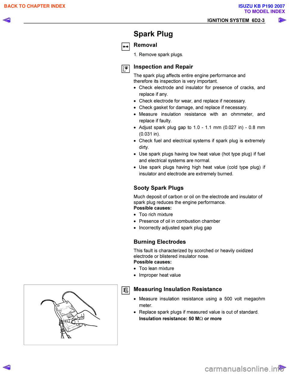
Measuring Insulation Resistance
• Measure insulation resistance using a 500 volt megaohm
meter.
• Replace spark plugs if measured value is out of standard.
Insulation resistance: 50 M Ω or more
BACK TO CHAPTER INDEX
TO MODEL INDEX
ISUZU KB P190 2007
Page 2147 of 6020
6D2-4 IGNITION SYSTEM
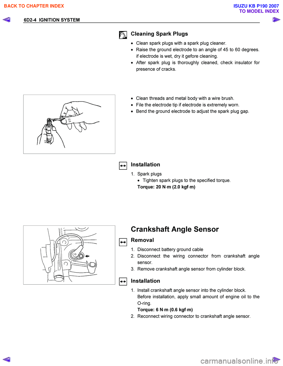
Cleaning Spark Plugs
• Clean spark plugs with a spark plug cleaner.
• Raise the ground electrode to an angle of 45 to 60 degrees.
if electrode is wet, dry it gefore cleaning.
•
After spark plug is thoroughly cleaned, check insulator for
presence of cracks.
• Clean threads and metal body with a wire brush.
• File the electrode tip if electrode is extremely worn.
• Bend the ground electrode to adjust the spark plug gap.
Installation
1. Spark plugs
• Tighten spark plugs to the specified torque.
Torque: 20 N ⋅m (2.0 kgf ⋅m)
Crankshaft Angle Sensor
Removal
1. Disconnect battery ground cable
2. Disconnect the wiring connector from crankshaft angle sensor.
3. Remove crankshaft angle sensor from cylinder block.
Installation
1. Install crankshaft angle sensor into the cylinder block.
Before installation, apply small amount of engine oil to the O-ring.
Torque: 6 N ⋅m (0.6 kgf ⋅m)
2. Reconnect wiring connector to crankshaft angle sensor.
BACK TO CHAPTER INDEX
TO MODEL INDEX
ISUZU KB P190 2007
Page 2156 of 6020
6D3-8 STARTING AND CHARGING SYSTEM
General On-Vehicle Inspection
The operating condition of charging system is indicated by the
charge warning lamp. The warning lamp comes on when the
starter switch is turned to "ON" position. The charging system
operates normally if the lamp goes off when the engine starts.
If the warning lamp shows abnormality or if undercharged or
overcharged battery condition is suspected, perform diagnosis
by checking the charging system as follows:
1. Check visually the belt and wiring connector.
2. W ith the engine stopped, turn the stator switch to "ON" position and observe the warning lamp.
If lamp does not come on:
Disconnect wiring connector from generator, and ground the terminal "L" on connector side.
If lamp comes on:
Repair or replace the generator.
Generator
Removal
1. Disconnect battery ground cable.
2. Move drive belt tensioner to loose side using wrench then remove drive belt.
3. Disconnect terminal "B" wiring connector and connector.
4. Remove generator assembly.
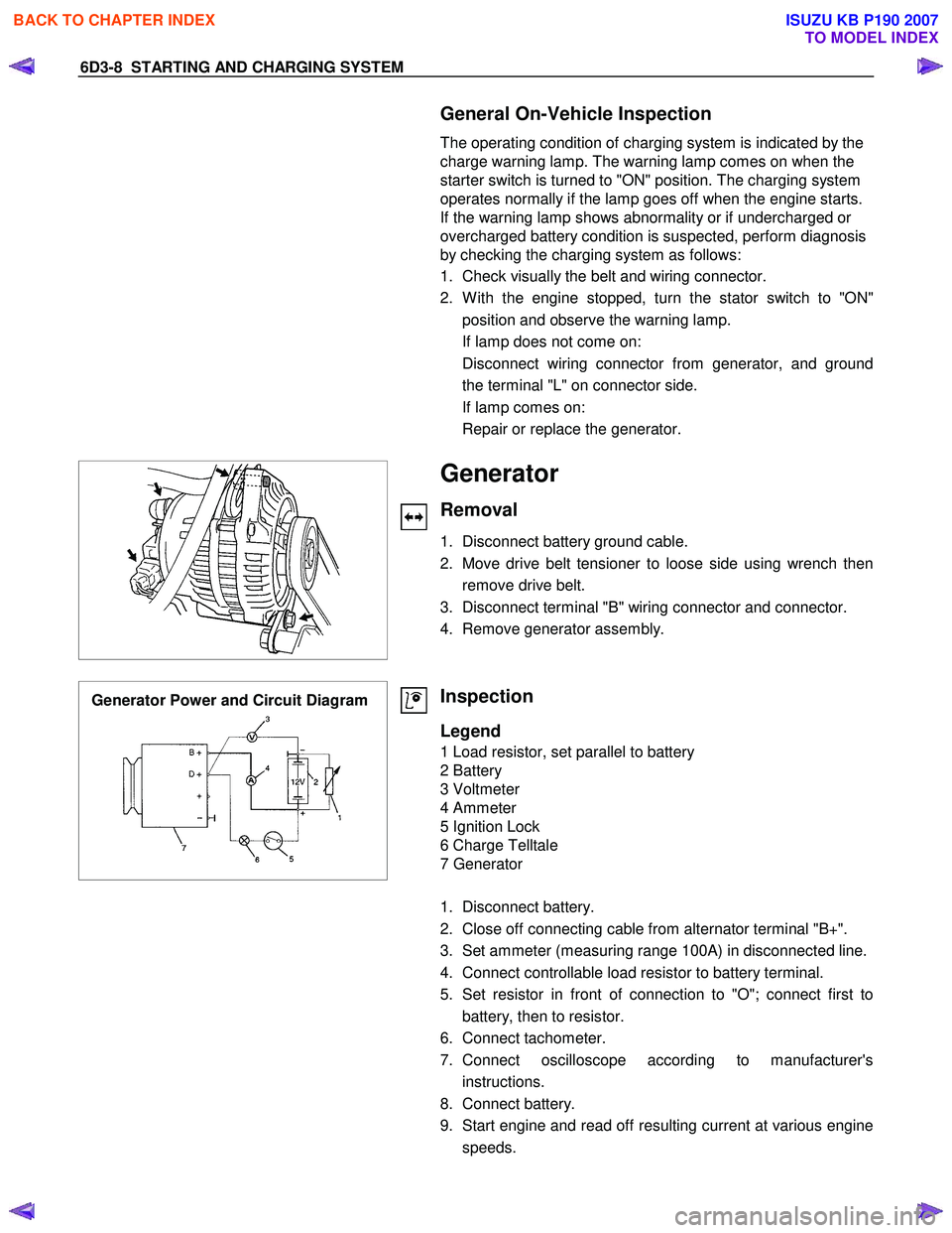
Generator Power and Circuit Diagram
Inspection
Legend
1 Load resistor, set parallel to battery
2 Battery
3 Voltmeter
4 Ammeter
5 Ignition Lock
6 Charge Telltale
7 Generator
1. Disconnect battery.
2. Close off connecting cable from alternator terminal "B+".
3. Set ammeter (measuring range 100A) in disconnected line.
4. Connect controllable load resistor to battery terminal.
5. Set resistor in front of connection to "O"; connect first to battery, then to resistor.
6. Connect tachometer.
7. Connect oscilloscope according to manufacturer's instructions.
8. Connect battery.
9. Start engine and read off resulting current at various engine speeds.
BACK TO CHAPTER INDEX
TO MODEL INDEX
ISUZU KB P190 2007
Page 2167 of 6020
STARTING AND CHARGING SYSTEM 6D3-19
Inspection
Generator
Before any in field testing can be undertaken it is important
that the battery's conditions is established and the terminals
are clean and tight.
Check the condition of the generator drive belt and ensure that
it is adjusted in accordance with the engine manufacturer's
recommnedations.
Battery conditions:
Note: This assessment may be difficult with maintenance free
assemblies.
Test the specific gravity of the individual cells the readings
should be within 10 points of each other, it is recommended
that the average SG should be 1.260 or higher.
A load test should be carried out to determine the ability of the
battery to supply and accept current. This is a good indicator
as to the general condition of the battery.
A load equal to the normal starting current should be placed
across the battery, the duration of this load test should not
exceed 10 seconds, during this time the terminal voltage
across the battery should not drop below 9.6 volts. Observe
each cell for signs of excessive gas liberation, usuall an
indication of cell failure.
If the battery test is clear proceed with the Generator tests as
follows.
Care should be taken when making the following connections.
It is recommended that the battery negative terminal be
disconnected before the test meters are connected, and
reconnecting the negative terminal when the meters are
inserted into the circuit under test. The warning lamp in the D+
circuit should not exceed 2 watts.
Regulating voltage test on the vehicle.
Connect a voltmeter to the generator, the positive lead to the
B+ terminal and the nagative lead to the generator casing.
Select the voltage range to suit the system, i.e. 20v for 12 volt
sysytems or 40v for 24 volt systems. Connect an ammeter in
series with the main output cable from the B+ terminal on the
generator, the range selected must be capable of reading the
maximum output from the generator.
Note the voltmeter reading before starting the engine. This
reading should increase when the engine is running indicating
generator output, start the engine and increase the engine
speed until the generator is running at 4000 rpm, switch on
vehicle loads of 5-10 A is indcated on the ammeter, the
voltmeter shoud read 14.0-14.2 v for a 12 volt system, for a 24
volt system the readings should be 5-10 A and 27.7-28.5 volts.
BACK TO CHAPTER INDEX
TO MODEL INDEX
ISUZU KB P190 2007
Page 2171 of 6020
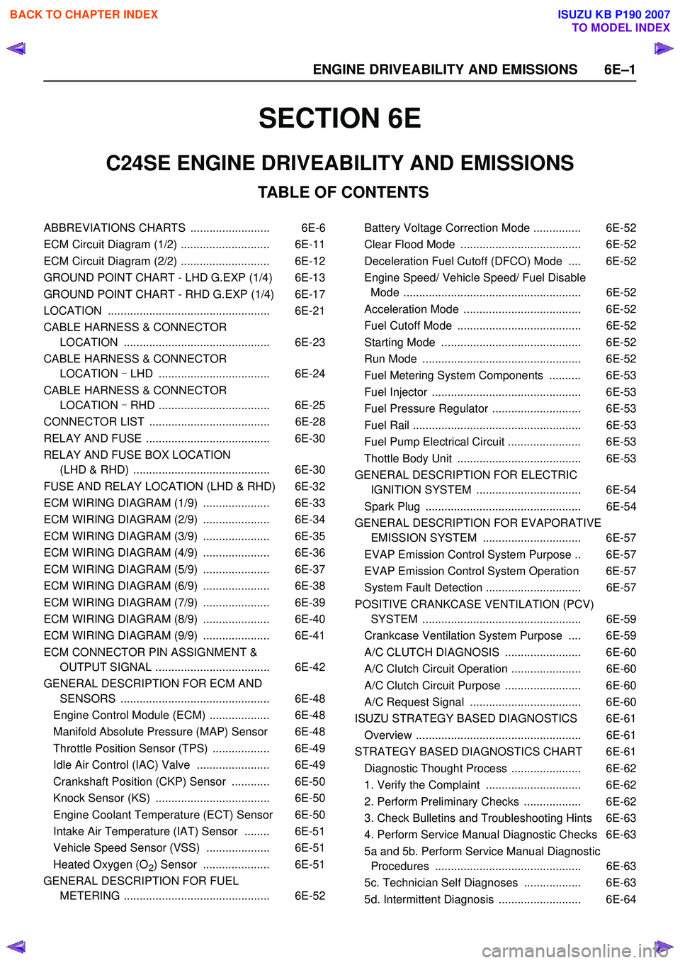
SECTION 6E
TABLE OF CONTENTS
C24SE ENGINE DRIVEABILITY AND EMISSIONS
ABBREVIATIONS CHARTS ......................... 6E-6
ECM Circuit Diagram (1/2) ............................ 6E-11
ECM Circuit Diagram (2/2) ............................ 6E-12
GROUND POINT CHART - LHD G.EXP (1/4) 6E-13
GROUND POINT CHART - RHD G.EXP (1/4) 6E-17
LOCATION ................................................... 6E-21
CABLE HARNESS & CONNECTOR LOCATION .............................................. 6E-23
CABLE HARNESS & CONNECTOR LOCATION - LHD ................................... 6E-24
CABLE HARNESS & CONNECTOR LOCATION - RHD ................................... 6E-25
CONNECTOR LIST ...................................... 6E-28
RELAY AND FUSE ....................................... 6E-30
RELAY AND FUSE BOX LOCATION (LHD & RHD) ........................................... 6E-30
FUSE AND RELAY LOCATION (LHD & RHD) 6E-32
ECM WIRING DIAGRAM (1/9) ..................... 6E-33
ECM WIRING DIAGRAM (2/9) ..................... 6E-34
ECM WIRING DIAGRAM (3/9) ..................... 6E-35
ECM WIRING DIAGRAM (4/9) ..................... 6E-36
ECM WIRING DIAGRAM (5/9) ..................... 6E-37
ECM WIRING DIAGRAM (6/9) ..................... 6E-38
ECM WIRING DIAGRAM (7/9) ..................... 6E-39
ECM WIRING DIAGRAM (8/9) ..................... 6E-40
ECM WIRING DIAGRAM (9/9) ..................... 6E-41
ECM CONNECTOR PIN ASSIGNMENT & OUTPUT SIGNAL .................................... 6E-42
GENERAL DESCRIPTION FOR ECM AND SENSORS ............................................... 6E-48
Engine Control Module (ECM) ................... 6E-48
Manifold Absolute Pressure (MAP) Sensor 6E-48
Throttle Position Sensor (TPS) .................. 6E-49
Idle Air Control (IAC) Valve ....................... 6E-49
Crankshaft Position (CKP) Sensor ............ 6E-50
Knock Sensor (KS) .................................... 6E-50
Engine Coolant Temperature (ECT) Sensor 6E-50
Intake Air Temperature (IAT) Sensor ........ 6E-51
Vehicle Speed Sensor (VSS) .................... 6E-51
Heated Oxygen (O
2) Sensor ..................... 6E-51
GENERAL DESCRIPTION FOR FUEL METERING .............................................. 6E-52 Battery Voltage Correction Mode ............... 6E-52
Clear Flood Mode ...................................... 6E-52
Deceleration Fuel Cutoff (DFCO) Mode .... 6E-52
Engine Speed/ Vehicle Speed/ Fuel Disable Mode ........................................................ 6E-52
Acceleration Mode ..................................... 6E-52
Fuel Cutoff Mode ....................................... 6E-52
Starting Mode ............................................ 6E-52
Run Mode .................................................. 6E-52
Fuel Metering System Components .......... 6E-53
Fuel Injector ............................................... 6E-53
Fuel Pressure Regulator ............................ 6E-53
Fuel Rail ..................................................... 6E-53
Fuel Pump Electrical Circuit ....................... 6E-53
Thottle Body Unit ....................................... 6E-53
GENERAL DESCRIPTION FOR ELECTRIC IGNITION SYSTEM ................................. 6E-54
Spark Plug ................................................. 6E-54
GENERAL DESCRIPTION FOR EVAPORATIVE EMISSION SYSTEM ............................... 6E-57
EVAP Emission Control System Purpose .. 6E-57
EVAP Emission Control System Operation 6E-57
System Fault Detection .............................. 6E-57
POSITIVE CRANKCASE VENTILATION (PCV) SYSTEM .................................................. 6E-59
Crankcase Ventilation System Purpose .... 6E-59
A/C CLUTCH DIAGNOSIS ........................ 6E-60
A/C Clutch Circuit Operation ...................... 6E-60
A/C Clutch Circuit Purpose ........................ 6E-60
A/C Request Signal ................................... 6E-60
ISUZU STRATEGY BASED DIAGNOSTICS 6E-61
Overview .................................................... 6E-61
STRATEGY BASED DIAGNOSTICS CHART 6E-61 Diagnostic Thought Process ...................... 6E-62
1. Verify the Complaint .............................. 6E-62
2. Perform Preliminary Checks .................. 6E-62
3. Check Bulletins and Troubleshooting Hints 6E-63
4. Perform Service Manual Diagnostic Checks 6E-63
5a and 5b. Perform Service Manual Diagnostic Procedures .............................................. 6E-63
5c. Technician Self Diagnoses .................. 6E-63
5d. Intermittent Diagnosis .......................... 6E-64
6 E –1
E N GINE DRIV EABILITY AND E M IS SIONS
BACK TO CHAPTER INDEX
TO MODEL INDEX
ISUZU KB P190 2007
Page 2172 of 6020
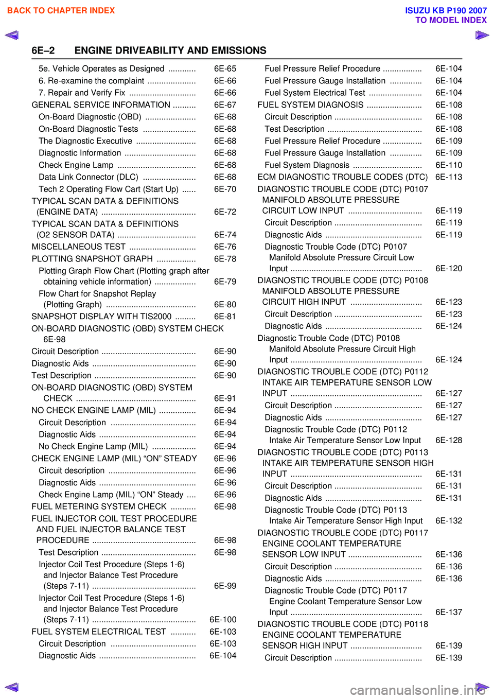
6E–2 ENGINE DRIVEABILITY AND EMISSIONS
5e. Vehicle Operates as Designed ............ 6E-65
6. Re-examine the complaint ..................... 6E-66
7. Repair and Verify Fix ............................. 6E-66
GENERAL SERVICE INFORMATION .......... 6E-67 On-Board Diagnostic (OBD) ...................... 6E-68
On-Board Diagnostic Tests ....................... 6E-68
The Diagnostic Executive .......................... 6E-68
Diagnostic Information ............................... 6E-68
Check Engine Lamp .................................. 6E-68
Data Link Connector (DLC) ....................... 6E-68
Tech 2 Operating Flow Cart (Start Up) ...... 6E-70
TYPICAL SCAN DATA & DEFINITIONS (ENGINE DATA) ......................................... 6E-72
TYPICAL SCAN DATA & DEFINITIONS (O2 SENSOR DATA) .................................. 6E-74
MISCELLANEOUS TEST ............................. 6E-76
PLOTTING SNAPSHOT GRAPH ................. 6E-78 Plotting Graph Flow Chart (Plotting graph after obtaining vehicle information) .................. 6E-79
Flow Chart for Snapshot Replay (Plotting Graph) ....................................... 6E-80
SNAPSHOT DISPLAY WITH TIS2000 ......... 6E-81
ON-BOARD DIAGNOSTIC (OBD) SYSTEM CHECK 6E-98
Circuit Description ......................................... 6E-90
Diagnostic Aids ............................................. 6E-90
Test Description ............................................ 6E-90
ON-BOARD DIAGNOSTIC (OBD) SYSTEM CHECK .................................................... 6E-91
NO CHECK ENGINE LAMP (MIL) ................ 6E-94 Circuit Description ..................................... 6E-94
Diagnostic Aids .......................................... 6E-94
No Check Engine Lamp (MIL) ................... 6E-94
CHECK ENGINE LAMP (MIL) “ON” STEADY 6E-96 Circuit description ...................................... 6E-96
Diagnostic Aids .......................................... 6E-96
Check Engine Lamp (MIL) “ON” Steady .... 6E-96
FUEL METERING SYSTEM CHECK ........... 6E-98
FUEL INJECTOR COIL TEST PROCEDURE AND FUEL INJECTOR BALANCE TEST
PROCEDURE ............................................. 6E-98
Test Description ......................................... 6E-98
Injector Coil Test Procedure (Steps 1-6) and Injector Balance Test Procedure
(Steps 7-11) ............................................. 6E-99
Injector Coil Test Procedure (Steps 1-6) and Injector Balance Test Procedure
(Steps 7-11) ............................................. 6E-100
FUEL SYSTEM ELECTRICAL TEST ........... 6E-103 Circuit Description ..................................... 6E-103
Diagnostic Aids .......................................... 6E-104 Fuel Pressure Relief Procedure ................. 6E-104
Fuel Pressure Gauge Installation .............. 6E-104
Fuel System Electrical Test ....................... 6E-104
FUEL SYSTEM DIAGNOSIS ........................ 6E-108 Circuit Description ...................................... 6E-108
Test Description ......................................... 6E-108
Fuel Pressure Relief Procedure ................. 6E-109
Fuel Pressure Gauge Installation .............. 6E-109
Fuel System Diagnosis .............................. 6E-110
ECM DIAGNOSTIC TROUBLE CODES (DTC) 6E-113
DIAGNOSTIC TROUBLE CODE (DTC) P0107 MANIFOLD ABSOLUTE PRESSURE
CIRCUIT LOW INPUT ................................ 6E-119
Circuit Description ...................................... 6E-119
Diagnostic Aids .......................................... 6E-119
Diagnostic Trouble Code (DTC) P0107 Manifold Absolute Pressure Circuit Low
Input ......................................................... 6E-120
DIAGNOSTIC TROUBLE CODE (DTC) P0108 MANIFOLD ABSOLUTE PRESSURE
CIRCUIT HIGH INPUT ............................... 6E-123
Circuit Description ...................................... 6E-123
Diagnostic Aids .......................................... 6E-124
Diagnostic Trouble Code (DTC) P0108 Manifold Absolute Pressure Circuit High
Input ......................................................... 6E-124
DIAGNOSTIC TROUBLE CODE (DTC) P0112 INTAKE AIR TEMPERATURE SENSOR LOW
INPUT ......................................................... 6E-127
Circuit Description ...................................... 6E-127
Diagnostic Aids .......................................... 6E-127
Diagnostic Trouble Code (DTC) P0112 Intake Air Temperature Sensor Low Input 6E-128
DIAGNOSTIC TROUBLE CODE (DTC) P0113 INTAKE AIR TEMPERATURE SENSOR HIGH
INPUT ......................................................... 6E-131
Circuit Description ...................................... 6E-131
Diagnostic Aids .......................................... 6E-131
Diagnostic Trouble Code (DTC) P0113 Intake Air Temperature Sensor High Input 6E-132
DIAGNOSTIC TROUBLE CODE (DTC) P0117 ENGINE COOLANT TEMPERATURE
SENSOR LOW INPUT ................................ 6E-136
Circuit Description ...................................... 6E-136
Diagnostic Aids .......................................... 6E-136
Diagnostic Trouble Code (DTC) P0117 Engine Coolant Temperature Sensor Low
Input ......................................................... 6E-137
DIAGNOSTIC TROUBLE CODE (DTC) P0118 ENGINE COOLANT TEMPERATURE
SENSOR HIGH INPUT ............................... 6E-139
Circuit Description ...................................... 6E-139
BACK TO CHAPTER INDEX
TO MODEL INDEX
ISUZU KB P190 2007
Page 2174 of 6020
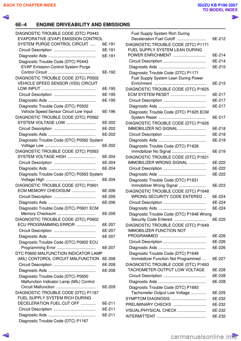
6E–4 ENGINE DRIVEABILITY AND EMISSIONS
DIAGNOSTIC TROUBLE CODE (DTC) P0443 EVAPORATIVE (EVAP) EMISSION CONTROL
SYSTEM PURGE CONTROL CIRCUIT ..... 6E-191
Circuit Description ..................................... 6E-191
Diagnostic Aids .......................................... 6E-191
Diagnostic Trouble Code (DTC) P0443 EVAP Emission Control System Purge
Control Circuit .......................................... 6E-192
DIAGNOSTIC TROUBLE CODE (DTC) P0502 VEHICLE SPEED SENSOR (VSS) CIRCUIT
LOW INPUT ................................................ 6E-195
Circuit Description ..................................... 6E-195
Diagnostic Aids .......................................... 6E-195
Diagnostic Trouble Code (DTC) P0502 Vehicle Speed Sensor Circuit Low Input . 6E-196
DIAGNOSTIC TROUBLE CODE (DTC) P0562 SYSTEM VOLTAGE LOW .......................... 6E-202
Circuit Description ..................................... 6E-202
Diagnostic Aids .......................................... 6E-202
Diagnostic Trouble Code (DTC) P0562 System Voltage Low ............................................. 6E-202
DIAGNOSTIC TROUBLE CODE (DTC) P0563 SYSTEM VOLTAGE HIGH ......................... 6E-204
Circuit Description ..................................... 6E-204
Diagnostic Aids .......................................... 6E-204
Diagnostic Trouble Code (DTC) P0563 System Voltage High ............................................ 6E-204
DIAGNOSTIC TROUBLE CODE (DTC) P0601 ECM MEMORY CHECKSUM ..................... 6E-206
Circuit Description ..................................... 6E-206
Diagnostic Aids .......................................... 6E-206
Diagnostic Trouble Code (DTC) P0601 ECM Memory Checksum .................................. 6E-206
DIAGNOSTIC TROUBLE CODE (DTC) P0602 ECU PROGRAMMING ERROR ................. 6E-207
Circuit Description ..................................... 6E-207
Diagnostic Aids .......................................... 6E-207
Diagnostic Trouble Code (DTC) P0602 ECU Programming Error .................................. 6E-207
DTC P0650 MALFUNCTION INDICATOR LAMP (MIL) CONTOROL CIRCUIT MALFUNCTION 6E-208
Circuit Description ..................................... 6E-208
Diagnostic Aids .......................................... 6E-208
Diagnostic Trouble Code (DTC) P0650 Malfunction Indicator Lamp (MIL) Control
Circuit Malfunction ................................... 6E-209
DIAGNOSTIC TROUBLE CODE (DTC) P1167 FUEL SUPPLY SYSTEM RICH DURING
DECELERATION FUEL CUT OFF ............. 6E-211
Circuit Description ..................................... 6E-211
Diagnostic Aids .......................................... 6E-211
Diagnostic Trouble Code (DTC) P1167 Fuel Supply System Rich During
Deceleration Fuel Cutoff .......................... 6E-212
DIAGNOSTIC TROUBLE CODE (DTC) P1171 FUEL SUPPLY SYSTEM LEAN DURING
POWER ENRICHMENT ............................. 6E-214
Circuit Description ...................................... 6E-214
Diagnostic Aids .......................................... 6E-215
Diagnostic Trouble Code (DTC) P1171 Fuel Supply System Lean During Power
Enrichment .............................................. 6E-215
DIAGNOSTIC TROUBLE CODE (DTC) P1625 ECM SYSTEM RESET ............................... 6E-217
Circuit Description ...................................... 6E-217
Diagnostic Aids .......................................... 6E-217
Diagnostic Trouble Code (DTC) P1625 ECM System Reset .......................................... 6E-217
DIAGNOSTIC TROUBLE CODE (DTC) P1626 IMMOBILIZER NO SIGNAL ........................ 6E-218
Circuit Description ...................................... 6E-218
Diagnostic Aids .......................................... 6E-218
Diagnostic Trouble Code (DTC) P1626 Immobilizer No Signal .............................. 6E-219
DIAGNOSTIC TROUBLE CODE (DTC) P1631 IMMOBILIZER WRONG SIGNAL ............... 6E-222
Circuit Description ...................................... 6E-222
Diagnostic Aids .......................................... 6E-222
Diagnostic Trouble Code (DTC) P1631 Immobilizer Wrong Signal ........................ 6E-223
DIAGNOSTIC TROUBLE CODE (DTC) P1648 WRONG SECURITY CODE ENTERED .. 6E-224
Circuit Description ...................................... 6E-224
Diagnostic Aids .......................................... 6E-224
Diagnostic Trouble Code (DTC) P1648 Wrong Security Code Entered ............................ 6E-225
DIAGNOSTIC TROUBLE CODE (DTC) P1649 IMMOBILIZER FUNCTION NOT
PROGRAMMED ......................................... 6E-226
Circuit Description ...................................... 6E-226
Diagnostic Aids .......................................... 6E-226
Diagnostic Trouble Code (DTC) P1649 Immobilizer Function Not Programmed ... 6E-227
DIAGNOSTIC TROUBLE CODE (DTC) P1693 TACHOMETER OUTPUT LOW VOLTAGE 6E-228
Circuit Description ...................................... 6E-228
Diagnostic Aids .......................................... 6E-228
Diagnostic Trouble Code (DTC) P1693 Tachometer Output Low Voltage ............. 6E-229
SYMPTOM DIAGNOSIS ............................... 6E-232
PRELIMINARY CHECKS ............................. 6E-232
VISUAL/PHYSICAL CHECK ......................... 6E-232
INTERMITTENT ........................................... 6E-232
BACK TO CHAPTER INDEX
TO MODEL INDEX
ISUZU KB P190 2007
Page 2176 of 6020
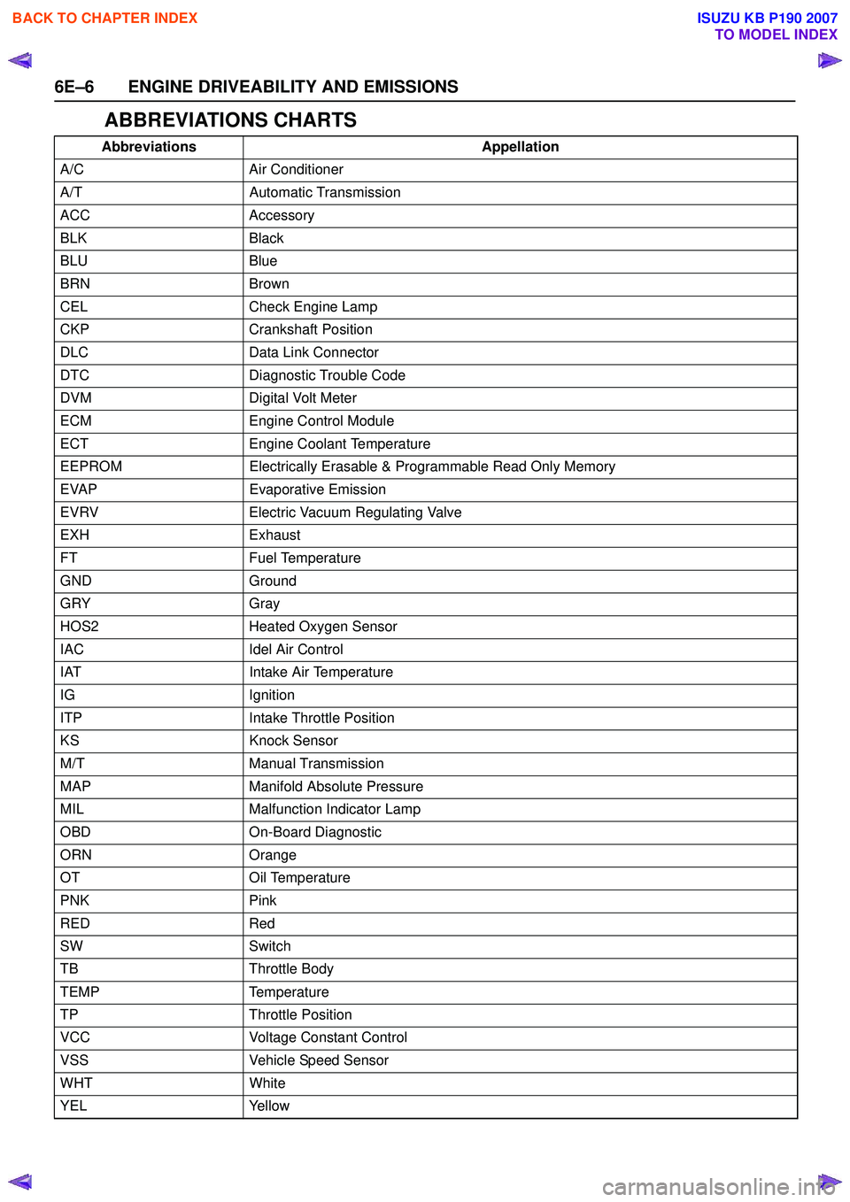
6E–6 ENGINE DRIVEABILITY AND EMISSIONS
ABBREVIATIONS CHARTS
AbbreviationsAppellation
A/C Air Conditioner
A/T Automatic Transmission
ACC Accessory
BLK Black
BLU Blue
BRN Brown
CEL Check Engine Lamp
CKP Crankshaft Position
DLC Data Link Connector
DTC Diagnostic Trouble Code
DVM Digital Volt Meter
ECM Engine Control Module
ECT Engine Coolant Temperature
EEPROM Electrically Erasable & Programmable Read Only Memory
EVAP Evaporative Emission
EVRV Electric Vacuum Regulating Valve
EXH Exhaust
FT Fuel Temperature
GND Ground
GRY Gray
HOS2 Heated Oxygen Sensor
IAC Idel Air Control
IAT Intake Air Temperature
IG Ignition
ITP Intake Throttle Position
KS Knock Sensor
M/T Manual Transmission
MAP Manifold Absolute Pressure
MIL Malfunction Indicator Lamp
OBD On-Board Diagnostic
ORN Orange
OT Oil Temperature
PNK Pink
RED Red
SW Switch
TB Throttle Body
TEMP Temperature
TP Throttle Position
VCC Voltage Constant Control
VSS Vehicle Speed Sensor
WHT White
YEL Yellow
BACK TO CHAPTER INDEX
TO MODEL INDEX
ISUZU KB P190 2007