2007 ISUZU KB P190 brake
[x] Cancel search: brakePage 4408 of 6020
7A2-124 TRANSMISSION CONTROL SYSTEM (JR405E)
Time Lag Test
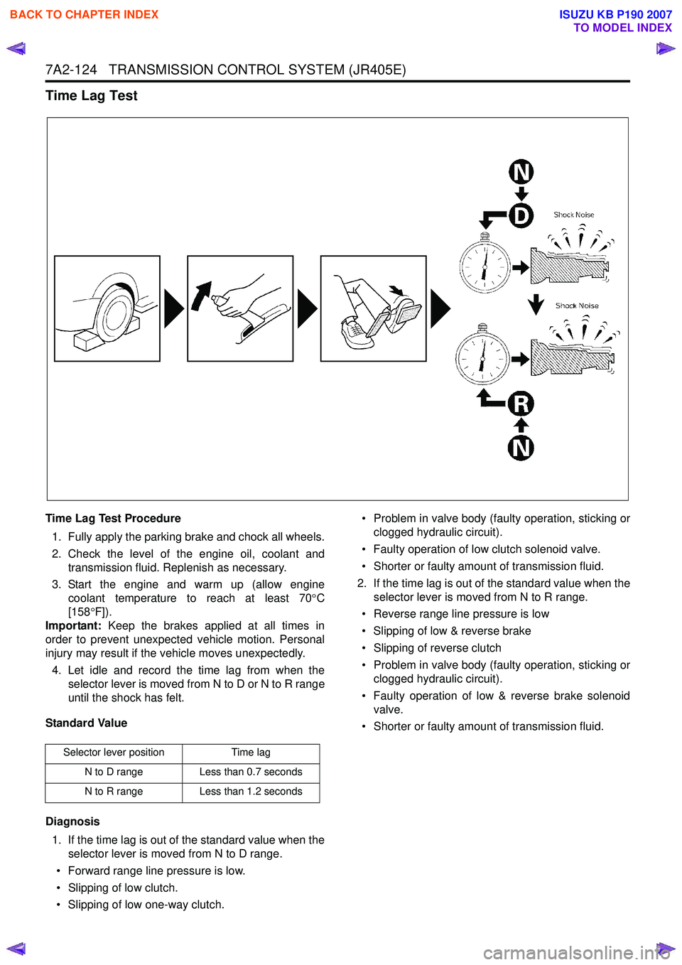
Time Lag Test Procedure1. Fully apply the parking brake and chock all wheels.
2. Check the level of the engine oil, coolant and transmission fluid. Replenish as necessary.
3. Start the engine and warm up (allow engine coolant temperature to reach at least 70 °C
[158 °F]).
Important: Keep the brakes applied at all times in
order to prevent unexpected vehicle motion. Personal
injury may result if the vehicle moves unexpectedly.
4. Let idle and record the time lag from when the selector lever is moved from N to D or N to R range
until the shock has felt.
Standard Value
Diagnosis 1. If the time lag is out of the standard value when the selector lever is moved from N to D range.
• Forward range line pressure is low.
• Slipping of low clutch.
• Slipping of low one-way clutch. • Problem in valve body (faulty operation, sticking or
clogged hydraulic circuit).
• Faulty operation of low clutch solenoid valve.
• Shorter or faulty amount of transmission fluid.
2. If the time lag is out of the standard value when the selector lever is moved from N to R range.
• Reverse range line pressure is low
• Slipping of low & reverse brake
• Slipping of reverse clutch
• Problem in valve body (faulty operation, sticking or clogged hydraulic circuit).
• Faulty operation of low & reverse brake solenoid valve.
• Shorter or faulty amount of transmission fluid.
Selector lever position Time lag
N to D range Less than 0.7 seconds
N to R range Less than 1.2 seconds
BACK TO CHAPTER INDEX
TO MODEL INDEX
ISUZU KB P190 2007
Page 4409 of 6020
TRANSMISSION CONTROL SYSTEM (JR405E) 7A2-125
Road Test
Road Test Procedure
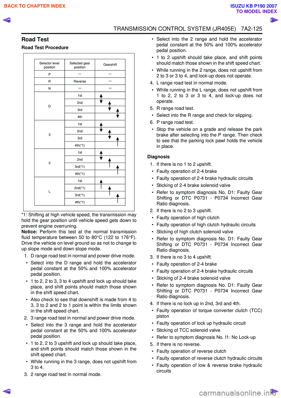
*1: Shifting at high vehicle speed, the transmission may
hold the gear position until vehicle speed gets down to
prevent engine overruning.
Notice: Perform this test at the normal transmission
fluid temperature between 50 to 80 °C (122 to 176 °F).
Drive the vehicle on level ground so as not to change to
up slope mode and down slope mode.
1. D range road test in normal and power drive mode. • Select into the D range and hold the accelerator pedal constant at the 50% and 100% accelerator
pedal position.
• 1 to 2, 2 to 3, 3 to 4 upshift and lock up should take place, and shift points should match those shown
in the shift speed chart.
• Also check to see that downshift is made from 4 to 3, 3 to 2 and 2 to 1 point is within the limits shown
in the shift speed chart.
2. 3 range road test in normal and power drive mode. • Select into the 3 range and hold the accelerator pedal constant at the 50% and 100% accelerator
pedal position.
• 1 to 2, 2 to 3 upshift and lock up should take place, and shift points should match those shown in the
shift speed chart.
• While running in the 3 range, does not upshift from 3 to 4.
3. 2 range road test in normal mode. • Select into the 2 range and hold the accelerator
pedal constant at the 50% and 100% accelerator
pedal position.
• 1 to 2 upshift should take place, and shift points should match those shown in the shift speed chart.
• While running in the 2 range, does not upshift from 2 to 3 or 3 to 4, and lock-up does not operate.
4. L range road test in normal mode.
• While running in the L range, does not upshift from 1 to 2, 2 to 3 or 3 to 4, and lock-up does not
operate.
5. R range road test. • Select into the R range and check for slipping.
6. P range road test. • Stop the vehicle on a grade and release the park brake after selecting into the P range. Then check
to see that the parking lock pawl holds the vehicle
in place.
Diagnosis 1. If there is no 1 to 2 upshift.• Faulty operation of 2-4 brake
• Faulty operation of 2-4 brake hydraulic circuits
• Sticking of 2-4 brake solenoid valve
• Refer to symptom diagnosis No. D1: Faulty Gear Shifting or DTC P0731 - P0734 Incorrect Gear
Ratio diagnosis.
2. If there is no 2 to 3 upshift.
• Faulty operation of high clutch
• Faulty operation of high clutch hydraulic circuits
• Sticking of high clutch solenoid valve
• Refer to symptom diagnosis No. D1: Faulty Gear Shifting or DTC P0731 - P0734 Incorrect Gear
Ratio diagnosis.
3. If there is no 3 to 4 upshift.
• Faulty operation of 2-4 brake
• Faulty operation of 2-4 brake hydraulic circuits
• Sticking of 2-4 brake solenoid valve
• Refer to symptom diagnosis No. D1: Faulty Gear Shifting or DTC P0731 - P0734 Incorrect Gear
Ratio diagnosis.
4. If there is no lock up in 2nd, 3rd and 4th. • Faulty operation of torque converter clutch (TCC) piston
• Faulty operation of lock up hydraulic circuit
• Sticking of TCC solenoid valve
• Refer to symptom diagnosis No. I1: No Lock-up
5. If there is no reverse. • Faulty operation of reverse clutch
• Faulty operation of reverse clutch hydraulic circuits
• Faulty operation of low & reverse brake hydraulic circuits
Selector lever
position GearshiftSelected gear
position
P
R
N
D
3
2
L 1st
2nd 3rd4th1st
2nd 3rd
4th(*1) 1st
2nd
3rd(*1) 4th(*1) 1st
2nd(*1) 3rd(*1)4th(*1)
Reverse
BACK TO CHAPTER INDEX
TO MODEL INDEX
ISUZU KB P190 2007
Page 4410 of 6020
7A2-126 TRANSMISSION CONTROL SYSTEM (JR405E)
• Sticking of low & reverse brake solenoid valve
• Refer to symptom diagnosis No. A2: Vehicle Dose Not Run in R Range
6. If there is no parking. • Faulty parking pawl
• Refer to symptom diagnosis No. G1: Vehicle Moves in P Range or Parking Gear in Not
Disengaged other than P Range.
Notice: The check for the cause of abnormal noise and
vibration must be made with extreme care as it could
also be due to loss of balance in the propeller shaft,
differential, the torque converter, etc. Or insufficient
bending, rigidity, etc. in the powertrain.
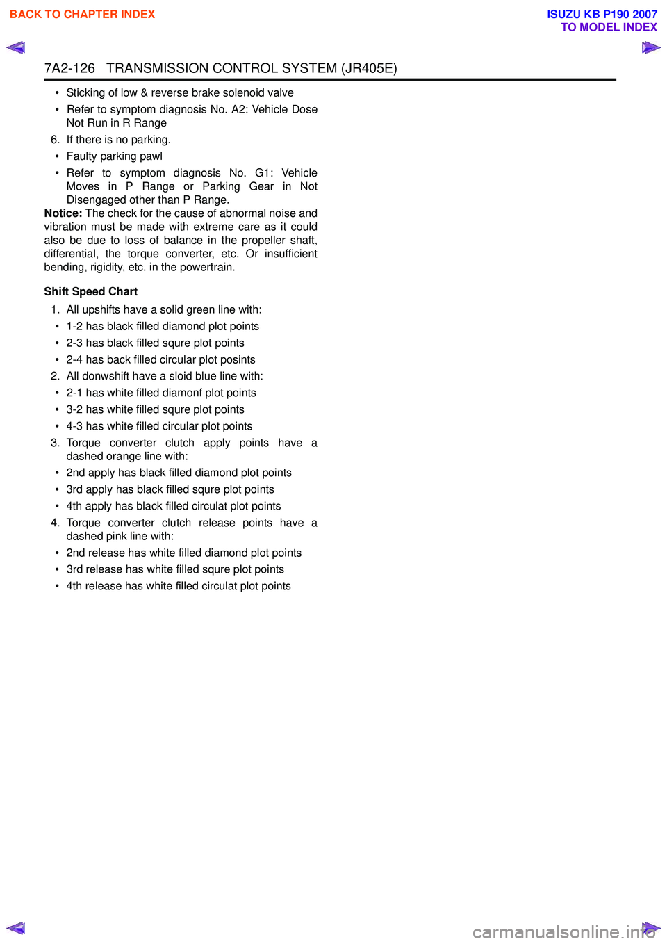
Shift Speed Chart 1. All upshifts have a solid green line with:• 1-2 has black filled diamond plot points
• 2-3 has black filled squre plot points
• 2-4 has back filled circular plot posints
2. All donwshift have a sloid blue line with:
• 2-1 has white filled diamonf plot points
• 3-2 has white filled squre plot points
• 4-3 has white filled circular plot points
3. Torque converter clutch apply points have a dashed orange line with:
• 2nd apply has black filled diamond plot points
• 3rd apply has black filled squre plot points
• 4th apply has black filled circulat plot points
4. Torque converter clutch release points have a dashed pink line with:
• 2nd release has white filled diamond plot points
• 3rd release has white filled squre plot points
• 4th release has white filled circulat plot points
BACK TO CHAPTER INDEX
TO MODEL INDEX
ISUZU KB P190 2007
Page 4418 of 6020
7A2-134 TRANSMISSION CONTROL SYSTEM (JR405E)
TCM Signal Test
Inspection Tool
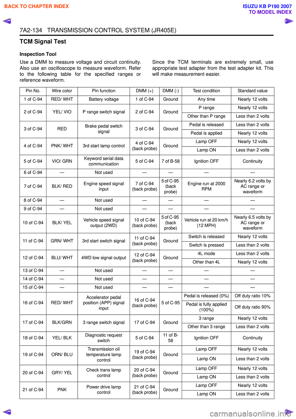
Use a DMM to measure voltage and circuit continuity.
Also use an oscilloscope to measure waveform. Refer
to the following table for the specified ranges or
reference waveform. Since the TCM terminals are extremely small, use
appropriate test adapter from the test adapter kit. This
will make measurement easier.
Pin No. Wire color Pin function DMM (+) DMM (-) Test condition Standard value
1 of C-94 RED/ WHT Battery voltage 1 of C-94 Ground Any time Nearly 12 volts
2 of C-94 YEL/ VIO P range switch signal 2 of C-94 Ground P range
Nearly 12 volts
Other than P range Less than 2 volts
3 of C-94 RED Brake pedal switch
signal 3 of C-94 Ground Pedal is released Less than 2 volts
Pedal is applied Nearly 12 volts
4 of C-94 PNK/ WHT 3rd start lamp control 4 of C-94
(back probe) Ground Lamp OFF Nearly 12 volts
Lamp ON Less than 2 volts
5 of C-94 VIO/ GRN Keyword serial data
communication 5 of C-94 7 of B-58 Ignition OFF
Continuity
6 of C-94 — Not used— — ——
7 of C-94 BLK/ RED Engine speed signal
input 7 of C-94
(back probe) 5 of C-95
(back
probe) Engine run at 2000
RPM Nearly 6.2 volts by
AC range or
waveform
8 of C-94 — Not used— — ——
9 of C-94 — Not used— — ——
10 of C-94 BLK/ YEL Vehicle speed signal
output (2WD) 10 of C-94
(back probe) 5 of C-95
(back
probe) Vehicle run at 20 km/h
(12 MPH) Nearly 6.5 volts by
AC range or waveform
11 of C-94 GRN/ WHT 3rd start switch signal 11 of C-94
(back probe) GroundSwitch is released Nearly 12 volts
Switch is pressed Less than 2 volts
12 of C-94 BLU/ WHT 4WD low signal output 12 of C-94
(back probe) Ground 4L mode Less than 2 volts
Other than 4L Nearly 12 volts
13 of C-94 — Not used— — ——
14 of C-94 — Not used— — ——
15 of C-94 — Not used— — ——
16 of C-94 RED/ WHT Accelerator pedal
position (APP) signal
input 16 of C-94
(back probe) 5 of C-95Pedal is released (0%) Off duty ratio 10%
Pedal is fully applied (100%) Off duty ratio 90%
17 of C-94 BLK/GRN 3 range switch signal 17 of C-94 Ground 3 range
Nearly 12 volts
Other than 3 range Less than 2 volts
18 of C-94 YEL/ BLK Diagnostic request
switch 5 of C-9411 o f B -
58 Ignition OFF
Continuity
19 of C-94 ORN/ BLU Transmission oil
temperature lamp control 19 of C-94
(back probe) Ground Lamp OFF Nearly 12 volts
Lamp ON Less than 2 volts
20 of C-94 GRY/ YEL Check trans lamp
control 20 of C-94
(back probe) Ground Lamp OFF Nearly 12 volts
Lamp ON Less than 2 volts
21 of C-94 PNK Power drive lamp
control 21 of C-94
(back probe) Ground Lamp OFF Nearly 12 volts
Lamp ON Less than 2 volts
BACK TO CHAPTER INDEX
TO MODEL INDEX
ISUZU KB P190 2007
Page 4419 of 6020
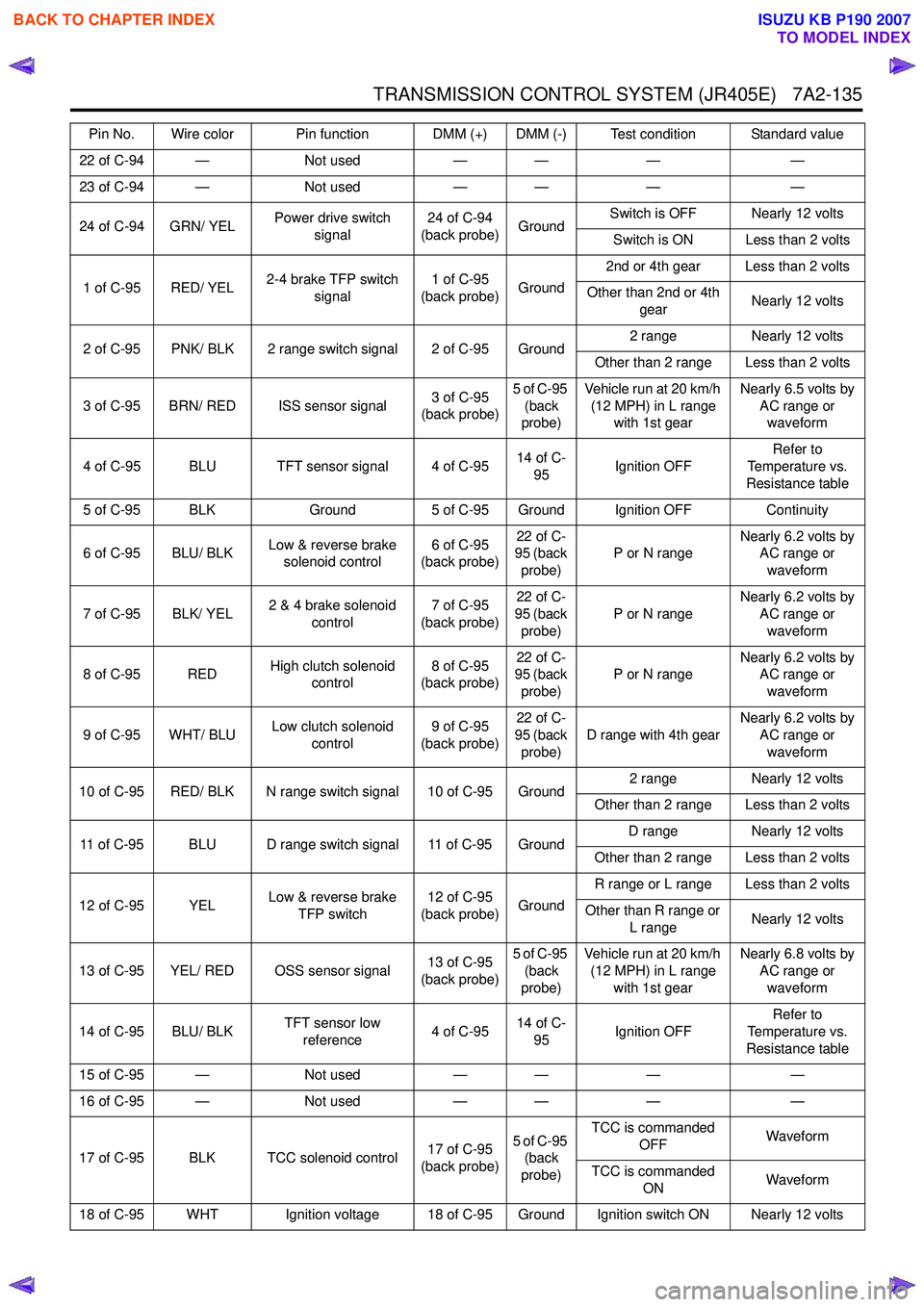
TRANSMISSION CONTROL SYSTEM (JR405E) 7A2-135
22 of C-94 —Not used— — ——
23 of C-94 — Not used— — ——
24 of C-94 GRN/ YEL Power drive switch
signal 24 of C-94
(back probe) GroundSwitch is OFF Nearly 12 volts
Switch is ON Less than 2 volts
1 of C-95 RED/ YEL 2-4 brake TFP switch
signal 1 of C-95
(back probe) Ground2nd or 4th gear Less than 2 volts
Other than 2nd or 4th gear Nearly 12 volts
2 of C-95 PNK/ BLK 2 range switch signal 2 of C-95 Ground 2 range
Nearly 12 volts
Other than 2 range Less than 2 volts
3 of C-95 BRN/ RED ISS sensor signal 3 of C-95
(back probe) 5 of C-95
(back
probe) Vehicle run at 20 km/h
(12 MPH) in L range with 1st gear Nearly 6.5 volts by
AC range or waveform
4 of C-95 BLU TFT sensor signal 4 of C-95 14 of C-
95 Ignition OFF Refer to
Temperature vs.
Resistance table
5 of C-95 BLK Ground5 of C-95 Ground Ignition OFF Continuity
6 of C-95 BLU/ BLK Low & reverse brake
solenoid control 6 of C-95
(back probe) 22 of C-
95 (back
probe) P or N range
Nearly 6.2 volts by
AC range or
waveform
7 of C-95 BLK/ YEL 2 & 4 brake solenoid
control 7 of C-95
(back probe) 22 of C-
95 (back
probe) P or N range
Nearly 6.2 volts by
AC range or
waveform
8 of C-95 RED High clutch solenoid
control 8 of C-95
(back probe) 22 of C-
95 (back
probe) P or N range
Nearly 6.2 volts by
AC range or
waveform
9 of C-95 WHT/ BLU Low clutch solenoid
control 9 of C-95
(back probe) 22 of C-
95 (back
probe) D range with 4th gear
Nearly 6.2 volts by
AC range or
waveform
10 of C-95 RED/ BLK N range switch signal 10 of C-95 Ground 2 range
Nearly 12 volts
Other than 2 range Less than 2 volts
11 of C-95 BLU D range switch signal 11 of C-95 Ground D range
Nearly 12 volts
Other than 2 range Less than 2 volts
12 of C-95 YEL Low & reverse brake
TFP switch 12 of C-95
(back probe) GroundR range or L range Less than 2 volts
Other than R range or L range Nearly 12 volts
13 of C-95 YEL/ RED OSS sensor signal 13 of C-95
(back probe) 5 of C-95
(back
probe) Vehicle run at 20 km/h
(12 MPH) in L range with 1st gear Nearly 6.8 volts by
AC range or waveform
14 of C-95 BLU/ BLK TFT sensor low
reference 4 of C-9514 of C-
95 Ignition OFF Refer to
Temperature vs.
Resistance table
15 of C-95 — Not used— — ——
16 of C-95 — Not used— — ——
17 of C-95 BLK TCC solenoid control 17 of C-95
(back probe) 5 of C-95
(back
probe) TCC is commanded
OFF Waveform
TCC is commanded ON Waveform
18 of C-95 WHT Ignition voltage 18 of C-95 Ground Ignition switch ON Nearly 12 volts Pin No. Wire color Pin function DMM (+) DMM (-) Test condition Standard value
BACK TO CHAPTER INDEX
TO MODEL INDEX
ISUZU KB P190 2007
Page 4421 of 6020
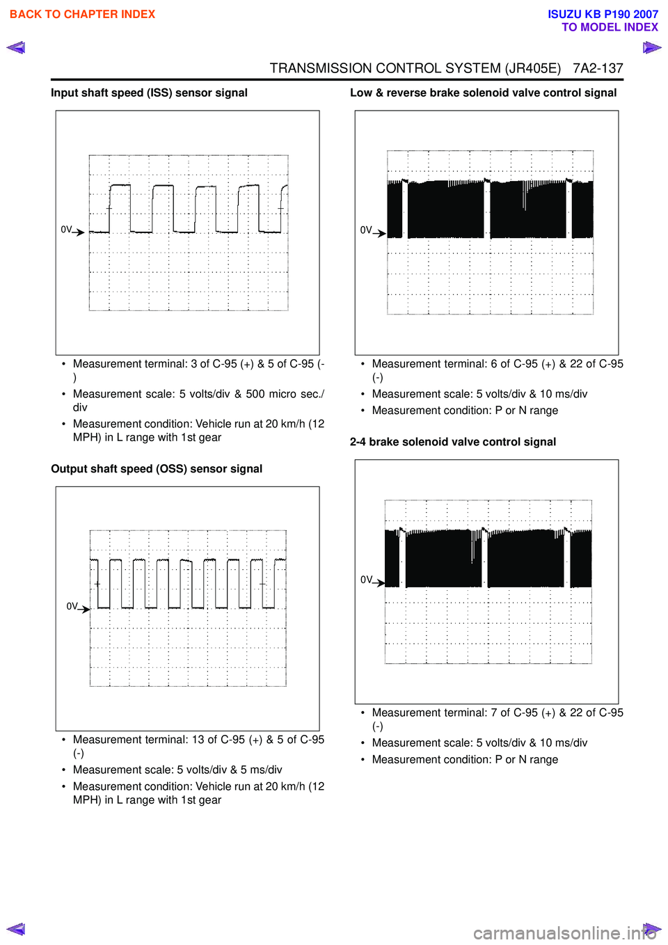
TRANSMISSION CONTROL SYSTEM (JR405E) 7A2-137
Input shaft speed (ISS) sensor signal• Measurement terminal: 3 of C-95 (+) & 5 of C-95 (- )
• Measurement scale: 5 volts/div & 500 micro sec./ div
• Measurement condition: Vehicle run at 20 km/h (12 MPH) in L range with 1st gear
Output shaft speed (OSS) sensor signal
• Measurement terminal: 13 of C-95 (+) & 5 of C-95 (-)
• Measurement scale: 5 volts/div & 5 ms/div
• Measurement condition: Vehicle run at 20 km/h (12 MPH) in L range with 1st gear Low & reverse brake solenoid valve control signal
• Measurement terminal: 6 of C-95 (+) & 22 of C-95 (-)
• Measurement scale: 5 volts/div & 10 ms/div
• Measurement condition: P or N range
2-4 brake solenoid valve control signal
• Measurement terminal: 7 of C-95 (+) & 22 of C-95 (-)
• Measurement scale: 5 volts/div & 10 ms/div
• Measurement condition: P or N range
0V
0V
0V
0V
BACK TO CHAPTER INDEX
TO MODEL INDEX
ISUZU KB P190 2007
Page 4427 of 6020
TRANSMISSION CONTROL SYSTEM (JR405E) 7A2-143
Description and Operation
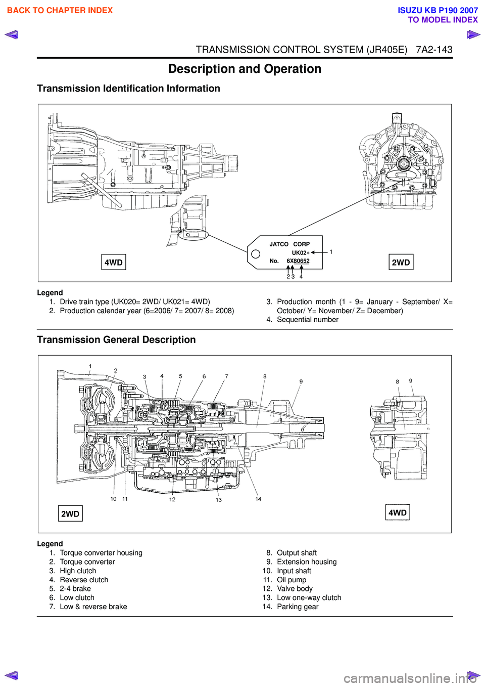
Transmission Identification Information
Legend1. Drive train type (UK020= 2WD/ UK021= 4WD)
2. Production calendar year (6=2006/ 7= 2007/ 8= 2008) 3. Production month (1 - 9= January - September/ X=
October/ Y= November/ Z= December)
4. Sequential number
Transmission General Description
Legend
1. Torque converter housing
2. Torque converter
3. High clutch
4. Reverse clutch
5. 2-4 brake
6. Low clutch
7. Low & reverse brake 8. Output shaft
9. Extension housing
10. Input shaft 11 . O i l p u m p
12. Valve body
13. Low one-way clutch
14. Parking gear
JATCO CORP
UK02
No. 6X80652 1
2 3 4
4WD
2WD
BACK TO CHAPTER INDEX
TO MODEL INDEX
ISUZU KB P190 2007
Page 4428 of 6020
7A2-144 TRANSMISSION CONTROL SYSTEM (JR405E)
The JR405E automatic transmission is electrically
controlled by a transmission control module (TCM).
There are four forward speeds and one reverse speed.
This JR405E automatic transmission employs a clutch
pressure direct control system (Direct Electronic Shift
Control: DESC) using duty cycle type solenoid valves,
which ensure high shift quality. This transmission also
has a learning function and constantly checks the time
of each clutch and brake required for the shift in order
to match this time with the target value for the optimum
shift. The TCM will automatically select the most
appropriate shift points and lock-up points depending
on the accelerator pedal opening, the vehicle speed
and the vehicle load. If any trouble arises in the speed
sensor, solenoid valve, etc., the fail-safe control
function is activated to keep the running performance.
The JR405E automatic transmission consists of the
torque converter, oil pump, input shaft, out put shaft,
planetary gears and valve body. The gear train consists
of two planetary gear sets and three multiple plate
clutches in combination with two multiple plate brakes
and a one-way clutch.
Transmission Component Description
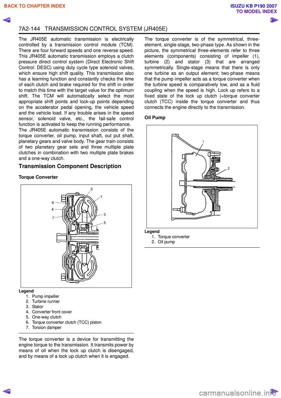
Torque Converter
Legend
1. Pump impeller
2. Turbine runner
3. Stator
4. Converter front cover
5. One-way clutch
6. Torque converter clutch (TCC) piston
7. Torsion damper
The torque converter is a device for transmitting the
engine torque to the transmission. It transmits power by
means of oil when the lock up clutch is disengaged,
and by means of a lock up clutch when it is engaged. The torque converter is of the symmetrical, three-
element, single-stage, two-phase type. As shown in the
picture, the symmetrical three-elements refer to three
elements (components) consisting of impeller (1),
turbine (2) and stator (3) that are arranged
symmetrically. Single-stage means that there is only
one turbine as an output element; two-phase means
that the pump impeller acts as a torque converter when
the turbine speed is comparatively low, and as a fluid
coupling when the speed is high. Lock up refers to a
fixed state of the lock up clutch (=torque converter
clutch (TCC) inside the torque converter and thus
connects the engine directly to the transmission.
Oil Pump
Legend 1. Torque converter
2. Oil pump
BACK TO CHAPTER INDEX
TO MODEL INDEX
ISUZU KB P190 2007