2007 ISUZU KB P190 fuel filter
[x] Cancel search: fuel filterPage 1499 of 6020
ENGINE MECHANICAL (4JK1/4JJ1) 6A-139
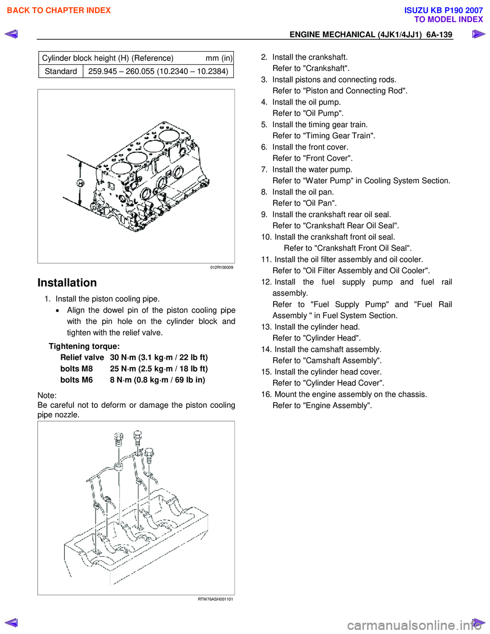
Cylinder block height (H) (Reference) mm (in)
Standard 259.945 – 260.055 (10.2340 – 10.2384)
012R100009
Installation
1. Install the piston cooling pipe.
• Align the dowel pin of the piston cooling pipe
with the pin hole on the cylinder block and
tighten with the relief valve.
Tightening torque: Relief valve 30 N ⋅
⋅⋅
⋅
m (3.1 kg ⋅
⋅⋅
⋅
m / 22 lb ft)
bolts M8 25 N ⋅
⋅⋅
⋅
m (2.5 kg ⋅
⋅⋅
⋅
m / 18 lb ft)
bolts M6 8 N ⋅
⋅⋅
⋅
m (0.8 kg ⋅
⋅⋅
⋅
m / 69 lb in)
Note:
Be careful not to deform or damage the piston cooling
pipe nozzle.
RTW 76ASH001101
2. Install the crankshaft.
Refer to "Crankshaft".
3. Install pistons and connecting rods.
Refer to "Piston and Connecting Rod".
4. Install the oil pump.
Refer to "Oil Pump".
5. Install the timing gear train.
Refer to "Timing Gear Train".
6. Install the front cover.
Refer to "Front Cover".
7. Install the water pump.
Refer to "W ater Pump" in Cooling System Section.
8. Install the oil pan.
Refer to "Oil Pan".
9. Install the crankshaft rear oil seal.
Refer to "Crankshaft Rear Oil Seal".
10. Install the crankshaft front oil seal. Refer to "Crankshaft Front Oil Seal".
11. Install the oil filter assembly and oil cooler.
Refer to "Oil Filter Assembly and Oil Cooler".
12. Install the fuel supply pump and fuel rail assembly.
Refer to "Fuel Supply Pump" and "Fuel Rail Assembly " in Fuel System Section.
13. Install the cylinder head.
Refer to "Cylinder Head".
14. Install the camshaft assembly.
Refer to "Camshaft Assembly".
15. Install the cylinder head cover.
Refer to "Cylinder Head Cover".
16. Mount the engine assembly on the chassis.
Refer to "Engine Assembly".
BACK TO CHAPTER INDEX
TO MODEL INDEX
ISUZU KB P190 2007
Page 1542 of 6020
FUEL SYSTEM (4JK1/4JJ1) 6C-1
SECTION 6C
FUEL SYSTEM
TABLE OF CONTENTS
Fuel System ....................................................... 6C-2 Service Precautions ........................................ 6C-2
Trouble Shooting ............................................. 6C-8
Fuel System Check ......................................... 6C-10
Fuel Filter Assembly ........................................... 6C-12 Components .................................................... 6C-12
Removal .......................................................... 6C-12
Installation ....................................................... 6C-12
Fuel Filter Cartridge............................................ 6C-13 Removal .......................................................... 6C-13
Installation ....................................................... 6C-13
Fuel Injector........................................................ 6C-14 Components .................................................... 6C-14
Removal .......................................................... 6C-15
Installation ....................................................... 6C-15
Torque Specifications...................................... 6C-18
Fuel Rail Pressure Sensor ................................. 6C-19 Removal .......................................................... 6C-19
Installation ....................................................... 6C-19
Fuel Pressure Limiter ......................................... 6C-20 Removal .......................................................... 6C-20
Installation ....................................................... 6C-20
Fuel Rail Assembly............................................. 6C-21 Components .................................................... 6C-21
Removal .......................................................... 6C-22
Disassembly .................................................... 6C-24
Reassembly..................................................... 6C-24
Installation ....................................................... 6C-24
Torque Specifications...................................... 6C-26
Fuel Supply Pump .............................................. 6C-27 Components .................................................... 6C-27
Removal .......................................................... 6C-28
Installation ....................................................... 6C-33
Torque Specifications...................................... 6C-38
Fuel Sedimenter Switch ..................................... 6C-39 Inspection ........................................................ 6C-39
Fuel Tank and Fuel Cooler ................................. 6C-40 Fuel Tank and Associated Parts ..................... 6C-40
Removal .......................................................... 6C-41
Installation ....................................................... 6C-41
Fuel Gauge Unit ................................................. 6C-42 Fuel Gauge Unit and Associated Parts ........... 6C-42
Removal .......................................................... 6C-43
Installation ....................................................... 6C-43
Special Tool .................................................... 6C-43
Fuel Tube/Quick-Connector Fittings .................. 6C-44 Precautions ..................................................... 6C-44
Cautions During W ork ..................................... 6C-44
Removal .......................................................... 6C-44
Reuse of Quick-Connector.............................. 6C-45
Assembling Advice .......................................... 6C-45
Filler Neck .......................................................... 6C-46 Removal .......................................................... 6C-46
Installation ....................................................... 6C-46
Fuel Filler Cap .................................................... 6C-47 General Description ........................................ 6C-47
Inspection ........................................................ 6C-47
BACK TO CHAPTER INDEX
TO MODEL INDEX
ISUZU KB P190 2007
Page 1544 of 6020
FUEL SYSTEM (4JK1/4JJ1) 6C-3
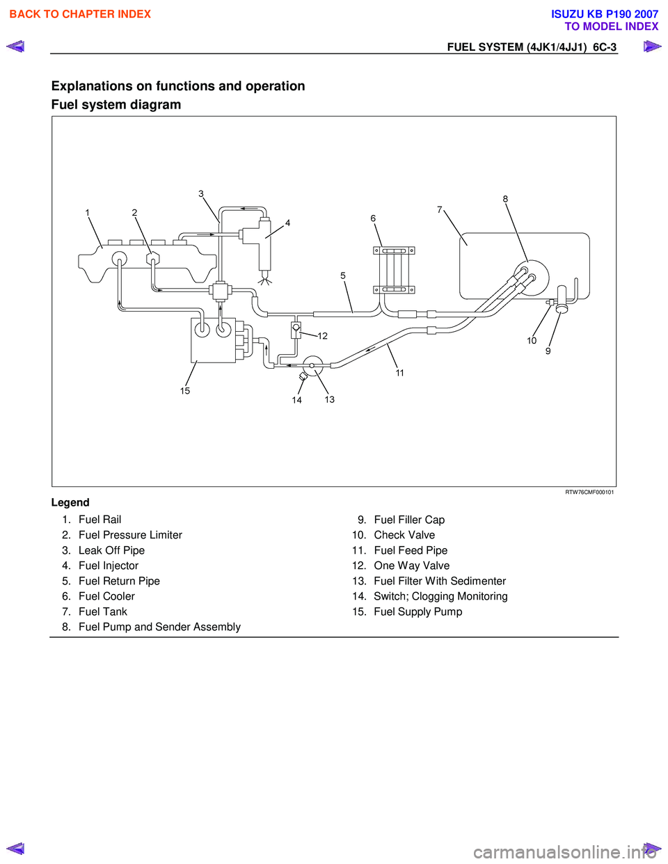
Explanations on functions and operation
Fuel system diagram
RTW 76CMF000101
Legend
1. Fuel Rail
2. Fuel Pressure Limiter
3. Leak Off Pipe
4. Fuel Injector
5. Fuel Return Pipe
6. Fuel Cooler
7. Fuel Tank
8. Fuel Pump and Sender Assembly
9. Fuel Filler Cap
10. Check Valve
11. Fuel Feed Pipe
12. One W ay Valve 13. Fuel Filter W ith Sedimenter
14. Switch; Clogging Monitoring
15. Fuel Supply Pump
BACK TO CHAPTER INDEX
TO MODEL INDEX
ISUZU KB P190 2007
Page 1547 of 6020
6C-6 FUEL SYSTEM (4JK1/4JJ1)
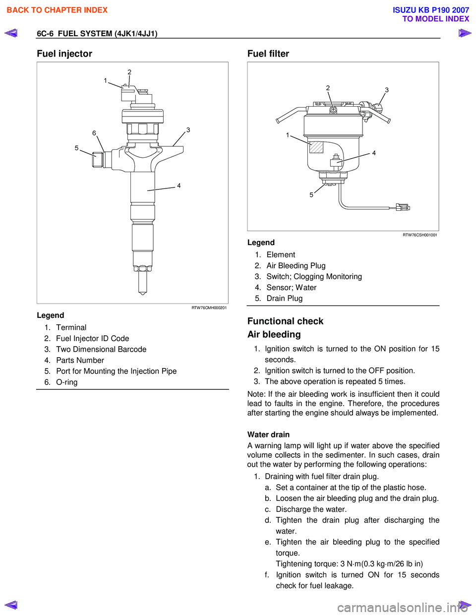
Fuel injector
RTW 76CMH000201
Legend
1. Terminal
2. Fuel Injector ID Code
3. Two Dimensional Barcode
4. Parts Number
5. Port for Mounting the Injection Pipe
6. O-ring
Fuel filter
RTW 76CSH001001
Legend
1. Element
2. Air Bleeding Plug
3. Switch; Clogging Monitoring
4. Sensor; W ater
5. Drain Plug
Functional check
Air bleeding
1. Ignition switch is turned to the ON position for 15 seconds.
2. Ignition switch is turned to the OFF position.
3. The above operation is repeated 5 times.
Note: If the air bleeding work is insufficient then it could
lead to faults in the engine. Therefore, the procedures
after starting the engine should always be implemented.
Water drain
A warning lamp will light up if water above the specified
volume collects in the sedimenter. In such cases, drain
out the water by performing the following operations:
1. Draining with fuel filter drain plug. a. Set a container at the tip of the plastic hose.
b. Loosen the air bleeding plug and the drain plug.
c. Discharge the water.
d. Tighten the drain plug after discharging the water.
e. Tighten the air bleeding plug to the specified torque.
Tightening torque: 3 N ⋅m(0.3 kg ⋅m/26 lb in)
f. Ignition switch is turned ON for 15 seconds check for fuel leakage.
BACK TO CHAPTER INDEX
TO MODEL INDEX
ISUZU KB P190 2007
Page 1549 of 6020
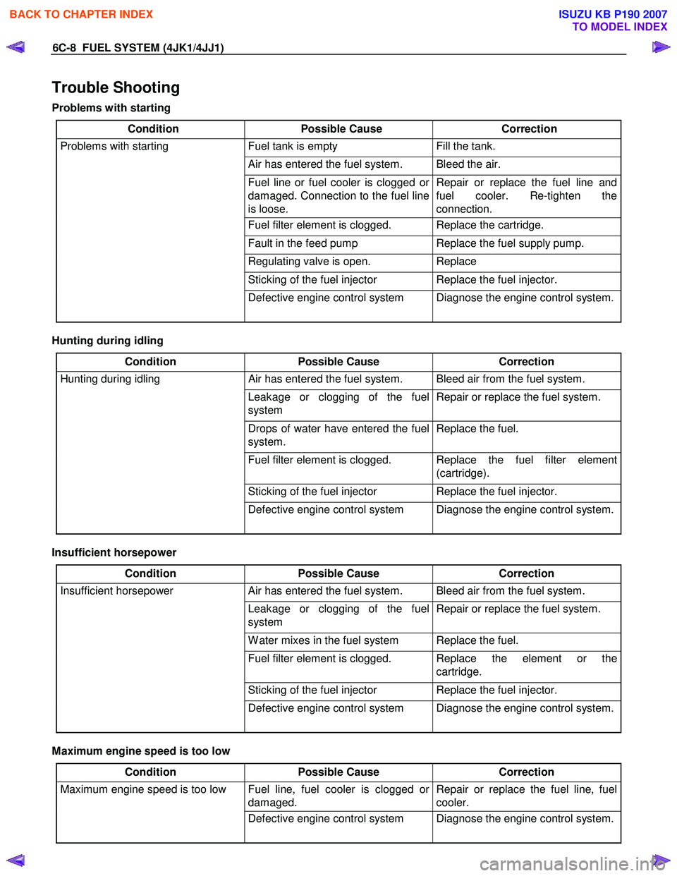
6C-8 FUEL SYSTEM (4JK1/4JJ1)
Trouble Shooting
Problems with starting
Condition Possible Cause Correction
Problems with starting Fuel tank is empty Fill the tank.
Air has entered the fuel system. Bleed the air.
Fuel line or fuel cooler is clogged or
damaged. Connection to the fuel line
is loose. Repair or replace the fuel line and
fuel cooler. Re-tighten the
connection.
Fuel filter element is clogged. Replace the cartridge.
Fault in the feed pump Replace the fuel supply pump.
Regulating valve is open. Replace
Sticking of the fuel injector Replace the fuel injector.
Defective engine control system Diagnose the engine control system.
Hunting during idling
Condition Possible Cause Correction
Hunting during idling Air has entered the fuel system. Bleed air from the fuel system.
Leakage or clogging of the fuel
system Repair or replace the fuel system.
Drops of water have entered the fuel
system. Replace the fuel.
Fuel filter element is clogged. Replace the fuel filter element
(cartridge).
Sticking of the fuel injector Replace the fuel injector.
Defective engine control system Diagnose the engine control system.
Insufficient horsepower
Condition Possible Cause Correction
Insufficient horsepower Air has entered the fuel system. Bleed air from the fuel system.
Leakage or clogging of the fuel
system Repair or replace the fuel system.
W ater mixes in the fuel system Replace the fuel.
Fuel filter element is clogged. Replace the element or the
cartridge.
Sticking of the fuel injector Replace the fuel injector.
Defective engine control system Diagnose the engine control system.
Maximum engine speed is too low
Condition Possible Cause Correction
Maximum engine speed is too low Fuel line, fuel cooler is clogged or
damaged. Repair or replace the fuel line, fuel
cooler.
Defective engine control system Diagnose the engine control system.
BACK TO CHAPTER INDEX
TO MODEL INDEX
ISUZU KB P190 2007
Page 1551 of 6020
6C-10 FUEL SYSTEM (4JK1/4JJ1)
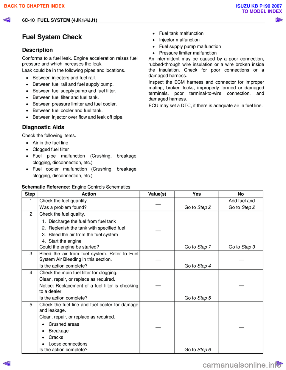
Fuel System Check
Description
Conforms to a fuel leak. Engine acceleration raises fuel
pressure and which increases the leak.
Leak could be in the following pipes and locations.
• Between injectors and fuel rail.
• Between fuel rail and fuel supply pump.
• Between fuel supply pump and fuel filter.
• Between fuel filter and fuel tank.
• Between pressure limiter and fuel cooler.
• Between fuel cooler and fuel tank.
• Between injector over flow and leak off pipe.
Diagnostic Aids
Check the following items.
• Air in the fuel line
• Clogged fuel filter
• Fuel pipe malfunction (Crushing, breakage,
clogging, disconnection, etc.)
• Fuel cooler malfunction (Crushing, breakage,
clogging, disconnection, etc.)
• Fuel tank malfunction
• Injector malfunction
• Fuel supply pump malfunction
• Pressure limiter malfunction
An intermittent may be caused by a poor connection,
rubbed-through wire insulation or a wire broken inside
the insulation. Check for poor connections or a
damaged harness.
Inspect the ECM harness and connector for imprope
r
mating, broken locks, improperly formed or damaged
terminals, poor terminal-to-wire connection, and
damaged harness.
ECU may set a DTC, if there is adequate air in fuel line.
Schematic Reference: Engine Controls Schematics
Step Action Value(s) Yes No
1 Check the fuel quantity. W as a problem found?
Go to Step 2 Add fuel and
Go to Step 2
2 Check the fuel quality.
1. Discharge the fuel from fuel tank
2. Replenish the tank with specified fuel
3. Bleed the air from the fuel system
4. Start the engine
Could the engine be started?
Go to Step 7 Go to Step 3
3 Bleed the air from fuel system. Refer to Fuel
System Air Bleeding in this section.
Is the action complete?
Go to Step 4
4 Check the main fuel filter for clogging.
Clean, repair, or replace as required.
Notice: Replacement of a fuel filter is checking
to a dealer.
Is the action complete?
Go to Step 5
5 Check the fuel line and fuel cooler for damage
and leakage.
Clean, repair, or replace as required.
• Crushed areas
• Breakage
• Cracks
• Loose connections
Is the action complete?
Go to Step 6
BACK TO CHAPTER INDEX
TO MODEL INDEX
ISUZU KB P190 2007
Page 1553 of 6020
6C-12 FUEL SYSTEM (4JK1/4JJ1)
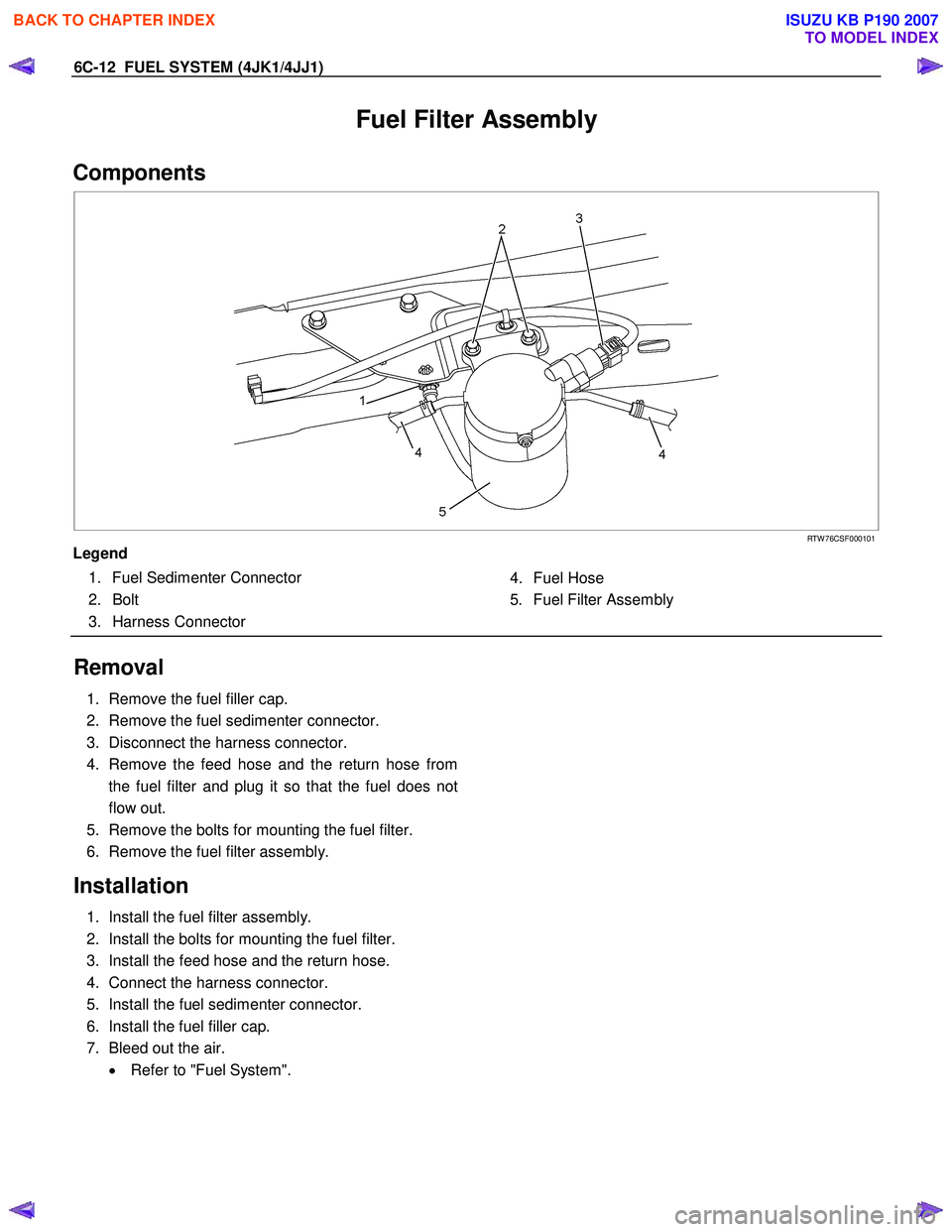
Fuel Filter Assembly
Components
RTW 76CSF000101
Legend
1. Fuel Sedimenter Connector 2. Bolt
3. Harness Connector
4. Fuel Hose
5. Fuel Filter Assembly
Removal
1. Remove the fuel filler cap.
2. Remove the fuel sedimenter connector.
3. Disconnect the harness connector.
4. Remove the feed hose and the return hose from the fuel filter and plug it so that the fuel does not
flow out.
5. Remove the bolts for mounting the fuel filter.
6. Remove the fuel filter assembly.
Installation
1. Install the fuel filter assembly.
2. Install the bolts for mounting the fuel filter.
3. Install the feed hose and the return hose.
4. Connect the harness connector.
5. Install the fuel sedimenter connector.
6. Install the fuel filler cap.
7. Bleed out the air. • Refer to "Fuel System".
BACK TO CHAPTER INDEX
TO MODEL INDEX
ISUZU KB P190 2007
Page 1554 of 6020
FUEL SYSTEM (4JK1/4JJ1) 6C-13
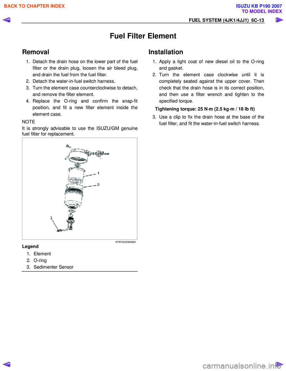
Fuel Filter Element
Removal
1. Detach the drain hose on the lower part of the fuel
filter or the drain plug, loosen the air bleed plug,
and drain the fuel from the fuel filter.
2. Detach the water-in-fuel switch harness.
3. Turn the element case counterclockwise to detach, and remove the filter element.
4. Replace the O-ring and confirm the snap-fit position, and fit a new filter element inside the
element case.
NOTE
It is strongly advisable to use the ISUZU/GM genuine
fuel filter for replacement.
RTW 76CSH000901
Legend
1. Element
2. O-ring
3. Sedimenter Sensor
Installation
1. Apply a light coat of new diesel oil to the O-ring
and gasket.
2. Turn the element case clockwise until it is completely seated against the upper cover. Then
check that the drain hose is in its correct position,
and then use a filter wrench and tighten to the
specified torque.
Tightening torque: 25 N ⋅
⋅⋅
⋅
m (2.5 kg ⋅
⋅⋅
⋅
m / 18 lb ft)
3. Use a clip to fix the drain hose at the base of the fuel filter, and fit the water-in-fuel switch harness.
BACK TO CHAPTER INDEX
TO MODEL INDEX
ISUZU KB P190 2007