2007 ISUZU KB P190 fuel filter
[x] Cancel search: fuel filterPage 965 of 6020

SECTION 6C
FUEL SYSTEM
TABLE OF CONTENTS
PAGE
Main Data and Specifications ....................................................................................... 6C - 2
General Description ...................................................................................................... 6C - 3
Fuel Flow.................................................................................................................... 6 C - 3
Fuel Filter and Water Separator ............................................................................... 6C - 4
Injection Pump........................................................................................................... 6C - 6
Injection Nozzle ......................................................................................................... 6C - 7
Fuel Tank...................................................................................................................... .. 6C - 8
Removal .................................................................................................................... 6 C - 9
Installation ................................................................................................................ 6C - 9
Fuel Gauge Unit ............................................................................................................. 6C - 11
Removal ..................................................................................................................... 6 C - 12
Installation ................................................................................................................. 6C - 12
Fuel Tube / Quick - Connector Fittings........................................................................ 6C - 14
Filler Neck .................................................................................................................... .. 6C - 16
Removal ..................................................................................................................... 6 C - 16
Installation ................................................................................................................. 6C - 16
Fuel Filler Cap................................................................................................................ 6C - 17
Injection Pump ............................................................................................................... 6 C - 18
Removal and Installation .......................................................................................... 6C - 18
Removal ..................................................................................................................... 6C - 18
Installation ................................................................................................................. 6 C - 21
Injection Nozzle (4JA1L) ............................................................................................... 6C - 25
Disassembly .............................................................................................................. 6C - 25
Reassembly ............................................................................................................... 6C - 26
Special tools .................................................................................................................. 6C - 37
FU
EL SY STEM 6C – 1
BACK TO CHAPTER INDEX
TO MODEL INDEX
ISUZU KB P190 2007
Page 966 of 6020

6C – 2 FUEL SYSTEM
MAIN DATA AND SPECIFICATIONS
Description Item
4JA1T (L) 4JA1TC 4JH1TC
Injection pump type Bosch distributor
VE type Bosch distributor VP44 type
Governor type
Mechanical variable
(Half speed oil pressure) Electrical controled
Timer type
Oil pressure Electrical controled
Fuel feed pump type Vane with input shaft
Injection nozzle type Hole type
Number of injection nozzle orifices 5
Injection nozzle orifices
Inside diameter mm (in) 0.19 (0.0075) 0.17 (0.0067) 0.21 (0.0083)
19.1 (195) 19.0 (194) 19.5 (199) Injection nozzle designed operating
pressure MPa (kg/cm2) 1st
2nd 25.0 (255)
33.5 (328) 33.8 (331)
Main fuel filter type Disposable cartridge paper element
Precautions
When working on the fuel system, there are several things
to keep in mind:
•
Any time the fuel system is being worked on,
disconnect the negative battery cable except fo
r
those tests where battery voltage is required.
•
Always keep a dry chemical (Class B) fire
extinguisher near the work area.
• Replace all pipes with the same pipe and fittings that
were removed.
• Clean and inspect “O” rings. Replace if required.
•
Always relieve the line pressure before servicing any
fuel system components.
• Do not attempt repairs on the fuel system until you
have read the instructions and checked the pictures
relating to that repair.
• Adhere to all Notices and Cautions.
NOTE:
Injection nozzle adjustment is possible only on the 4JA1L
engine.
BACK TO CHAPTER INDEX
TO MODEL INDEX
ISUZU KB P190 2007
Page 967 of 6020

FUEL SYSTEM 6C – 3
GENERAL DESCRIPTION
FUEL FLOW
RTW 66CMF000101
The fuel system consists of the fuel tank, the fuel filter, the water separator, the injection pump, and the injection
nozzle.
The fuel from the fuel tank passes through the water separator and the fuel filter where water particles and other
foreign material are removed from the fuel.
Fuel, fed by the injection pump plunger, is delivered to the injection nozzle in the measured volume at the optimum
timing for efficient engine operation.
NOTE:
1 If it find abnormal condition on the fuel injector, refer to section 6E ENGINE DRIVEABILITY AND EMISSIONS.
2 Do not contain "Additive for water drain" with fuel.
BACK TO CHAPTER INDEX
TO MODEL INDEX
ISUZU KB P190 2007
Page 968 of 6020

6C – 4 FUEL SYSTEM
FUEL FILTER AND WATER SEPARATOR
As the inside of the injection pump is lubricated by the fuel which it is pumping, the fuel must be perfectly clean. The
fuel filter and the water separator remove water particles and other foreign material from the fuel before it reaches
the injection pump.
The water separator has an internal float. W hen the float reaches the specified level, a warning light comes on to
remind you to drain the water from the water separator.
A diaphragm type priming pump is installed at the top of the fuel filter. It is used during the air bleeding procedures.
(Except EURO III model)
RTW 36CLF000701
BACK TO CHAPTER INDEX
TO MODEL INDEX
ISUZU KB P190 2007
Page 983 of 6020

FUEL SYSTEM 6C – 19
7. Power Steering Pump Bracket
6C-4 8. Throttle Position Sensor Harness Connector
(4JA1TC/4JH1TC only) Disconnect the harness connector from the throttle
position sensor.
9. Oil Level Gauge
10. Fuel Pipe 1) Disconnect the fuel hoses from the fuel filter or priming pump.
2) Disconnect the fuel hoses from the injection pump.
11. Fuel Filter Assembly (Except EURO III model)
6C-5
12. Fuel Filter Bracket (Except EURO III model)
13. Leak Off Hose
Disconnect the leak off hose at the injection pump.
14. Injection Pipe Clip
15. Injection Pipe
1) Loosen the injection pipe sleeve nuts at the delivery valve side and the injection nozzle side.
Note:
Do not apply excessive force to the injection pipes.
2) Loosen the injection pipe clip.
3) Remove the injection pipes.
Note:
Plug the delivery holder ports with the caps to prevent
the entry of foreign material.
16. Intake Manifold 1) Remove the EGR valve from the intake manifold and EGR pipe.
2) Loosen the intake rubber hoses clip.
3) Loosen the intake manifold bolts and nuts.
17. Injection Pump Cover (4JA1TC/4JH1TC only)
BACK TO CHAPTER INDEX
TO MODEL INDEX
ISUZU KB P190 2007
Page 987 of 6020

FUEL SYSTEM 6C – 23
6. Injection Pipe
Install the injection pipe.
Injection Pipe Torque N·m(kg·m / lb ft)
29 (3.0 / 22)
Nozzle Side (4JA1TC/4JH1TC) N·m(kg·m / lb ft)
29 (3.0 / 22)
Pump Side (4JA1TC/4JH1TC) N·m(kg·m / lb ft)
40 (4.1 / 30)
7. Injection Pipe Clip Install the injection pipe clip.
Note:
Make absolutely sure that the clip is correctly
positioned.
Injection Pipe Clip Torque N·m(kg·m / lb in)
8 (0.8 / 69)
8. Leak Off Pipe and Leak Off Hose
Install the leak off pipe to injection nozzle and connect the
leak off hose to the injection pump.
9. Fuel Filter Bracket (Except EURO III model)
Install the fuel filter bracket and tighten bolts to the
specified torque.
Fuel Filter Bracket Bolts Torque N·m(kg·m / lb ft)
21 (2.1 / 15)
10. Fuel Filter Assembly (Except EURO III model) Install the fuel filter assembly to bracket and tighten bolts
to the specified torque.
Fuel Filter Assembly Bolts
Torque N·m(kg·m / lb ft)
21 (2.1 / 15)
11. Fuel Pipe
1) Connect the fuel hoses to the fuel filter or priming pump.
2) Connect the fuel hoses to the injection pump.
12. Oil Level Gauge Install the oil level gauge and tighten bolts to the specified
torque.
Oil Level Gauge Bolts
Torque N·m(kg·m / lb ft)
M8: 19 (1.9 / 14)
M6: 8 (0.8/6 lb in)
BACK TO CHAPTER INDEX
TO MODEL INDEX
ISUZU KB P190 2007
Page 1053 of 6020

Engine Control System (4JH1) 6E-19
4
2
3 1
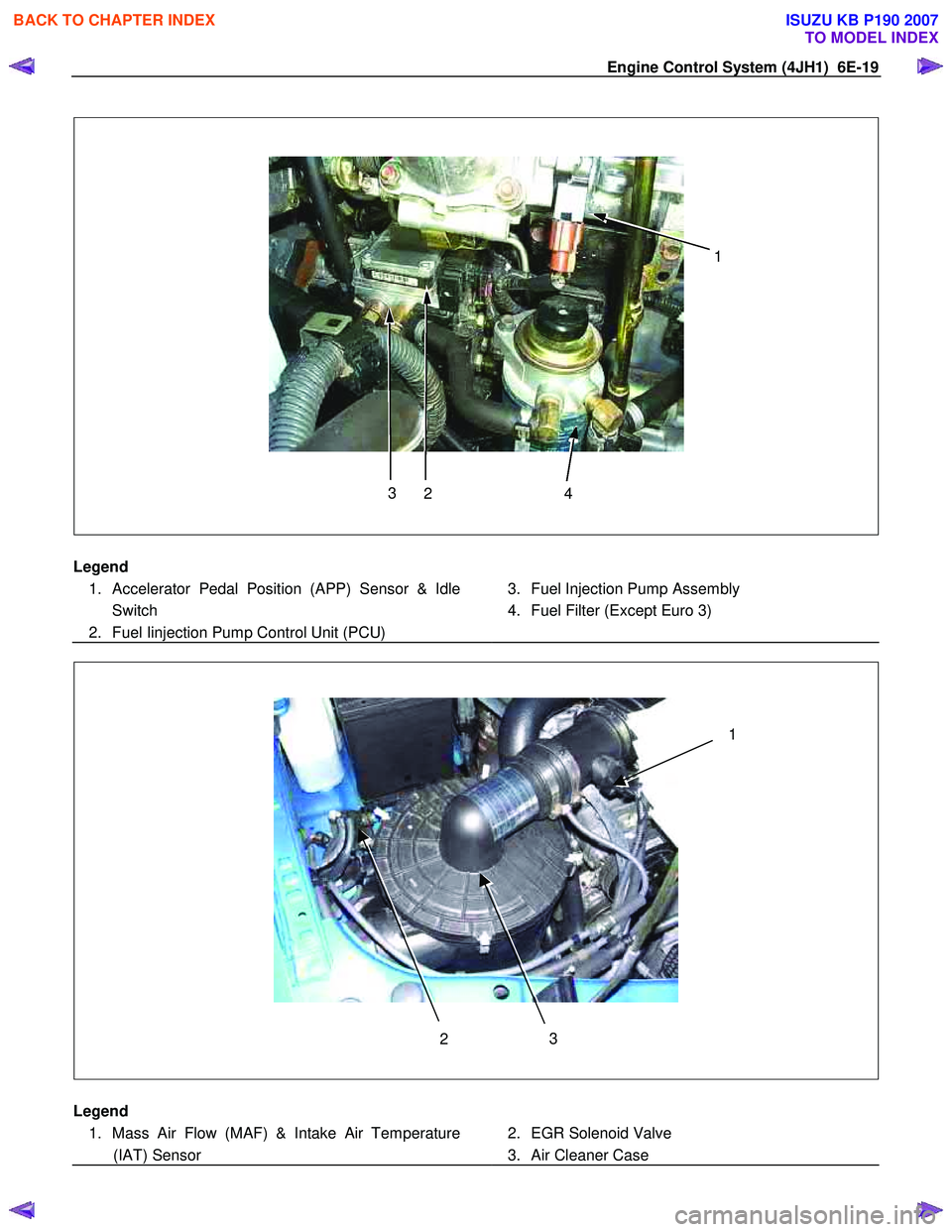
Legend
1. Accelerator Pedal Position (APP) Sensor & Idle Switch
2. Fuel Iinjection Pump Control Unit (PCU)
3. Fuel Injection Pump Assembly
4. Fuel Filter (Except Euro 3)
3
2 1
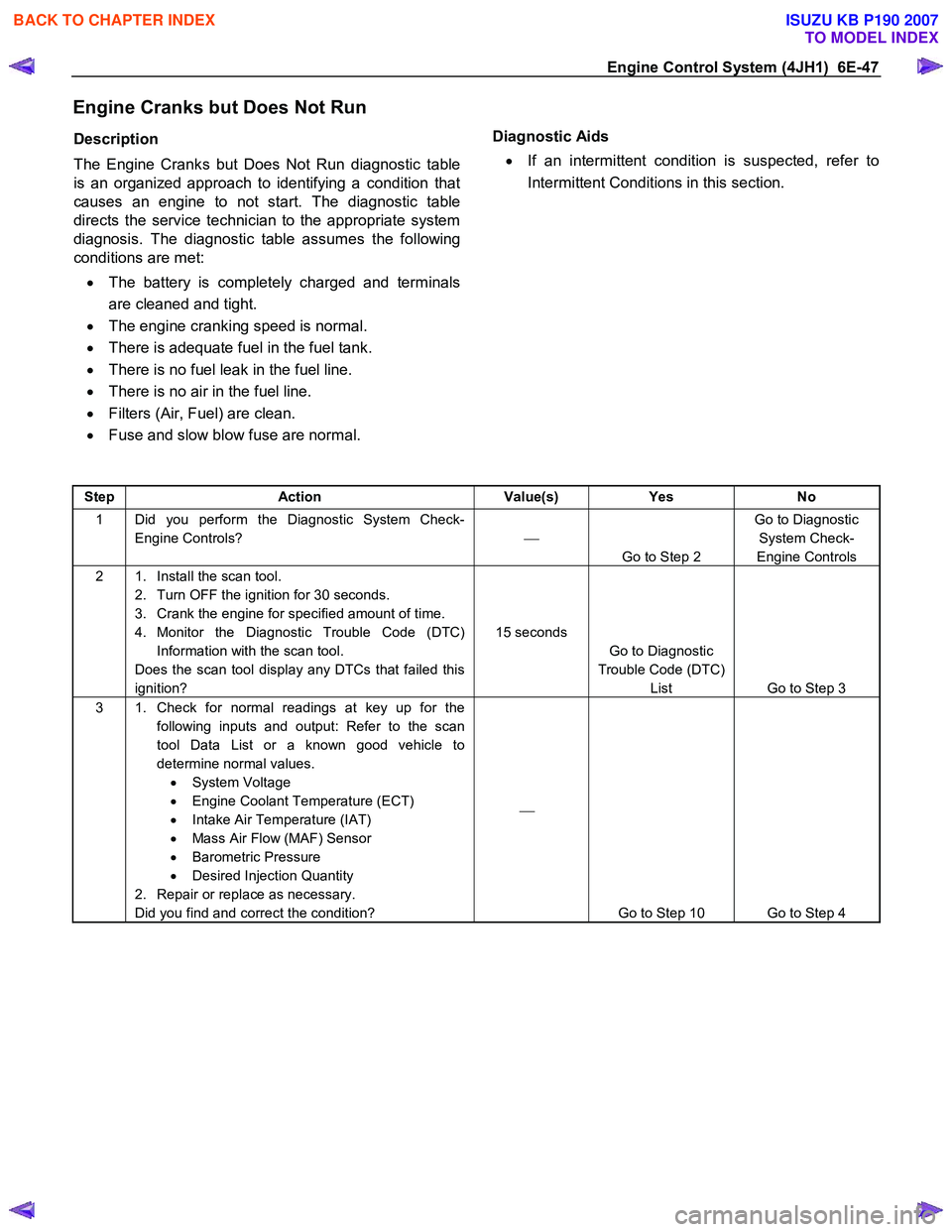
Legend
1. Mass Air Flow (MAF) & Intake Air Temperature (IAT) Sensor
2. EGR Solenoid Valve
3. Air Cleaner Case
BACK TO CHAPTER INDEX
TO MODEL INDEX
ISUZU KB P190 2007
Page 1081 of 6020

Engine Control System (4JH1) 6E-47
Engine Cranks but Does Not Run
Description
The Engine Cranks but Does Not Run diagnostic table
is an organized approach to identifying a condition that
causes an engine to not start. The diagnostic table
directs the service technician to the appropriate system
diagnosis. The diagnostic table assumes the following
conditions are met:
• The battery is completely charged and terminals
are cleaned and tight.
• The engine cranking speed is normal.
• There is adequate fuel in the fuel tank.
• There is no fuel leak in the fuel line.
• There is no air in the fuel line.
• Filters (Air, Fuel) are clean.
• Fuse and slow blow fuse are normal.
Diagnostic Aids
• If an intermittent condition is suspected, refer to
Intermittent Conditions in this section.
Step Action Value(s) Yes No
1 Did you perform the Diagnostic System Check-
Engine Controls?
Go to Step 2 Go to Diagnostic
System Check-
Engine Controls
2 1. Install the scan tool. 2. Turn OFF the ignition for 30 seconds.
3. Crank the engine for specified amount of time.
4. Monitor the Diagnostic Trouble Code (DTC) Information with the scan tool.
Does the scan tool display any DTCs that failed this
ignition? 15 seconds
Go to Diagnostic
Trouble Code (DTC) List Go to Step 3
3 1. Check for normal readings at key up for the
following inputs and output: Refer to the scan
tool Data List or a known good vehicle to
determine normal values. • System Voltage
• Engine Coolant Temperature (ECT)
• Intake Air Temperature (IAT)
• Mass Air Flow (MAF) Sensor
• Barometric Pressure
• Desired Injection Quantity
2. Repair or replace as necessary.
Did you find and correct the condition?
Go to Step 10 Go to Step 4
BACK TO CHAPTER INDEX
TO MODEL INDEX
ISUZU KB P190 2007