2007 ISUZU KB P190 Circuit
[x] Cancel search: CircuitPage 1893 of 6020
6E-276 ENGINE CONTROL SYSTEM (4JK1/4JJ1)
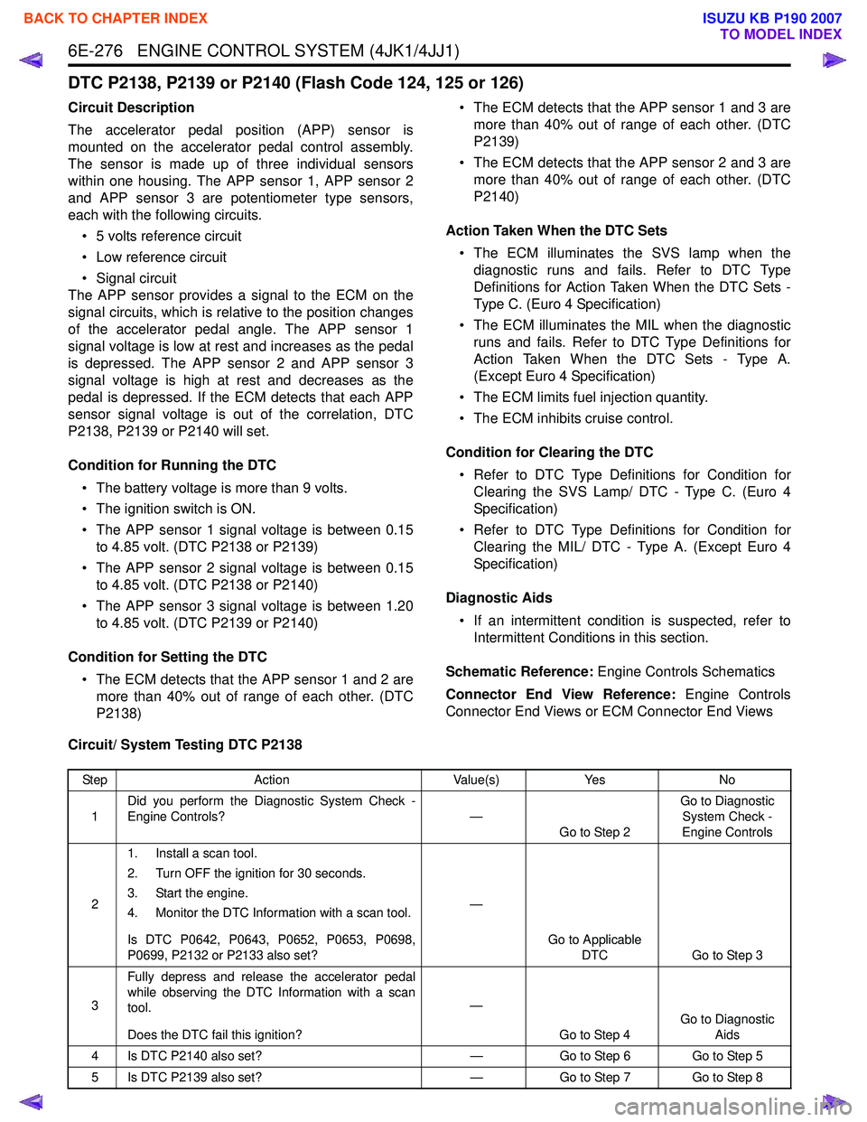
DTC P2138, P2139 or P2140 (Flash Code 124, 125 or 126)
Circuit Description
The accelerator pedal position (APP) sensor is
mounted on the accelerator pedal control assembly.
The sensor is made up of three individual sensors
within one housing. The APP sensor 1, APP sensor 2
and APP sensor 3 are potentiometer type sensors,
each with the following circuits.
• 5 volts reference circuit
• Low reference circuit
• Signal circuit
The APP sensor provides a signal to the ECM on the
signal circuits, which is relative to the position changes
of the accelerator pedal angle. The APP sensor 1
signal voltage is low at rest and increases as the pedal
is depressed. The APP sensor 2 and APP sensor 3
signal voltage is high at rest and decreases as the
pedal is depressed. If the ECM detects that each APP
sensor signal voltage is out of the correlation, DTC
P2138, P2139 or P2140 will set.
Condition for Running the DTC • The battery voltage is more than 9 volts.
• The ignition switch is ON.
• The APP sensor 1 signal voltage is between 0.15 to 4.85 volt. (DTC P2138 or P2139)
• The APP sensor 2 signal voltage is between 0.15 to 4.85 volt. (DTC P2138 or P2140)
• The APP sensor 3 signal voltage is between 1.20 to 4.85 volt. (DTC P2139 or P2140)
Condition for Setting the DTC • The ECM detects that the APP sensor 1 and 2 are more than 40% out of range of each other. (DTC
P2138) • The ECM detects that the APP sensor 1 and 3 are
more than 40% out of range of each other. (DTC
P2139)
• The ECM detects that the APP sensor 2 and 3 are more than 40% out of range of each other. (DTC
P2140)
Action Taken When the DTC Sets • The ECM illuminates the SVS lamp when the diagnostic runs and fails. Refer to DTC Type
Definitions for Action Taken When the DTC Sets -
Type C. (Euro 4 Specification)
• The ECM illuminates the MIL when the diagnostic runs and fails. Refer to DTC Type Definitions for
Action Taken When the DTC Sets - Type A.
(Except Euro 4 Specification)
• The ECM limits fuel injection quantity.
• The ECM inhibits cruise control.
Condition for Clearing the DTC • Refer to DTC Type Definitions for Condition for Clearing the SVS Lamp/ DTC - Type C. (Euro 4
Specification)
• Refer to DTC Type Definitions for Condition for Clearing the MIL/ DTC - Type A. (Except Euro 4
Specification)
Diagnostic Aids • If an intermittent condition is suspected, refer to Intermittent Conditions in this section.
Schematic Reference: Engine Controls Schematics
Connector End View Reference: Engine Controls
Connector End Views or ECM Connector End Views
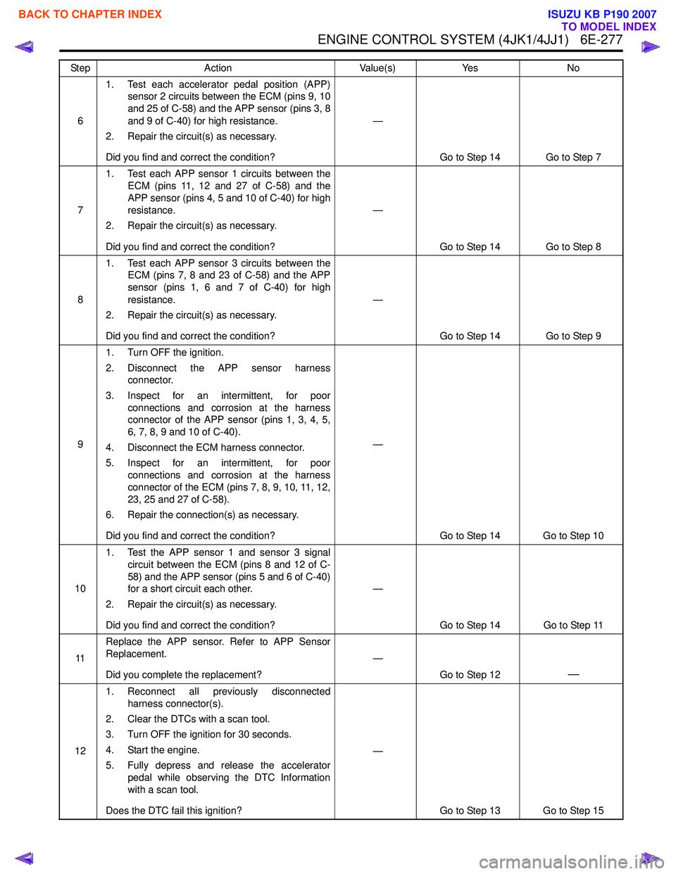
Circuit/ System Testing DTC P2138
Step Action Value(s)Yes No
1 Did you perform the Diagnostic System Check -
Engine Controls? —
Go to Step 2 Go to Diagnostic
System Check -
Engine Controls
2 1. Install a scan tool.
2. Turn OFF the ignition for 30 seconds.
3. Start the engine.
4. Monitor the DTC Information with a scan tool.
Is DTC P0642, P0643, P0652, P0653, P0698,
P0699, P2132 or P2133 also set? —
Go to Applicable DTC Go to Step 3
3 Fully depress and release the accelerator pedal
while observing the DTC Information with a scan
tool.
Does the DTC fail this ignition? —
Go to Step 4 Go to Diagnostic
Aids
4 Is DTC P2140 also set? —Go to Step 6 Go to Step 5
5 Is DTC P2139 also set? —Go to Step 7 Go to Step 8
BACK TO CHAPTER INDEX
TO MODEL INDEX
ISUZU KB P190 2007
Page 1894 of 6020
ENGINE CONTROL SYSTEM (4JK1/4JJ1) 6E-277
61. Test each accelerator pedal position (APP)
sensor 2 circuits between the ECM (pins 9, 10
and 25 of C-58) and the APP sensor (pins 3, 8
and 9 of C-40) for high resistance.
2. Repair the circuit(s) as necessary.
Did you find and correct the condition? —
Go to Step 14 Go to Step 7
7 1. Test each APP sensor 1 circuits between the
ECM (pins 11, 12 and 27 of C-58) and the
APP sensor (pins 4, 5 and 10 of C-40) for high
resistance.
2. Repair the circuit(s) as necessary.
Did you find and correct the condition? —
Go to Step 14 Go to Step 8
8 1. Test each APP sensor 3 circuits between the
ECM (pins 7, 8 and 23 of C-58) and the APP
sensor (pins 1, 6 and 7 of C-40) for high
resistance.
2. Repair the circuit(s) as necessary.
Did you find and correct the condition? —
Go to Step 14 Go to Step 9
9 1. Turn OFF the ignition.
2. Disconnect the APP sensor harness connector.
3. Inspect for an intermittent, for poor connections and corrosion at the harness
connector of the APP sensor (pins 1, 3, 4, 5,
6, 7, 8, 9 and 10 of C-40).
4. Disconnect the ECM harness connector.
5. Inspect for an intermittent, for poor connections and corrosion at the harness
connector of the ECM (pins 7, 8, 9, 10, 11, 12,
23, 25 and 27 of C-58).
6. Repair the connection(s) as necessary.
Did you find and correct the condition? —
Go to Step 14 Go to Step 10
10 1. Test the APP sensor 1 and sensor 3 signal
circuit between the ECM (pins 8 and 12 of C-
58) and the APP sensor (pins 5 and 6 of C-40)
for a short circuit each other.
2. Repair the circuit(s) as necessary.
Did you find and correct the condition? —
Go to Step 14 Go to Step 11
11 Replace the APP sensor. Refer to APP Sensor
Replacement.
Did you complete the replacement? —
Go to Step 12
—
121. Reconnect all previously disconnected
harness connector(s).
2. Clear the DTCs with a scan tool.
3. Turn OFF the ignition for 30 seconds.
4. Start the engine.
5. Fully depress and release the accelerator pedal while observing the DTC Information
with a scan tool.
Does the DTC fail this ignition? —
Go to Step 13 Go to Step 15
Step
Action Value(s)Yes No
BACK TO CHAPTER INDEX
TO MODEL INDEX
ISUZU KB P190 2007
Page 1895 of 6020
6E-278 ENGINE CONTROL SYSTEM (4JK1/4JJ1)
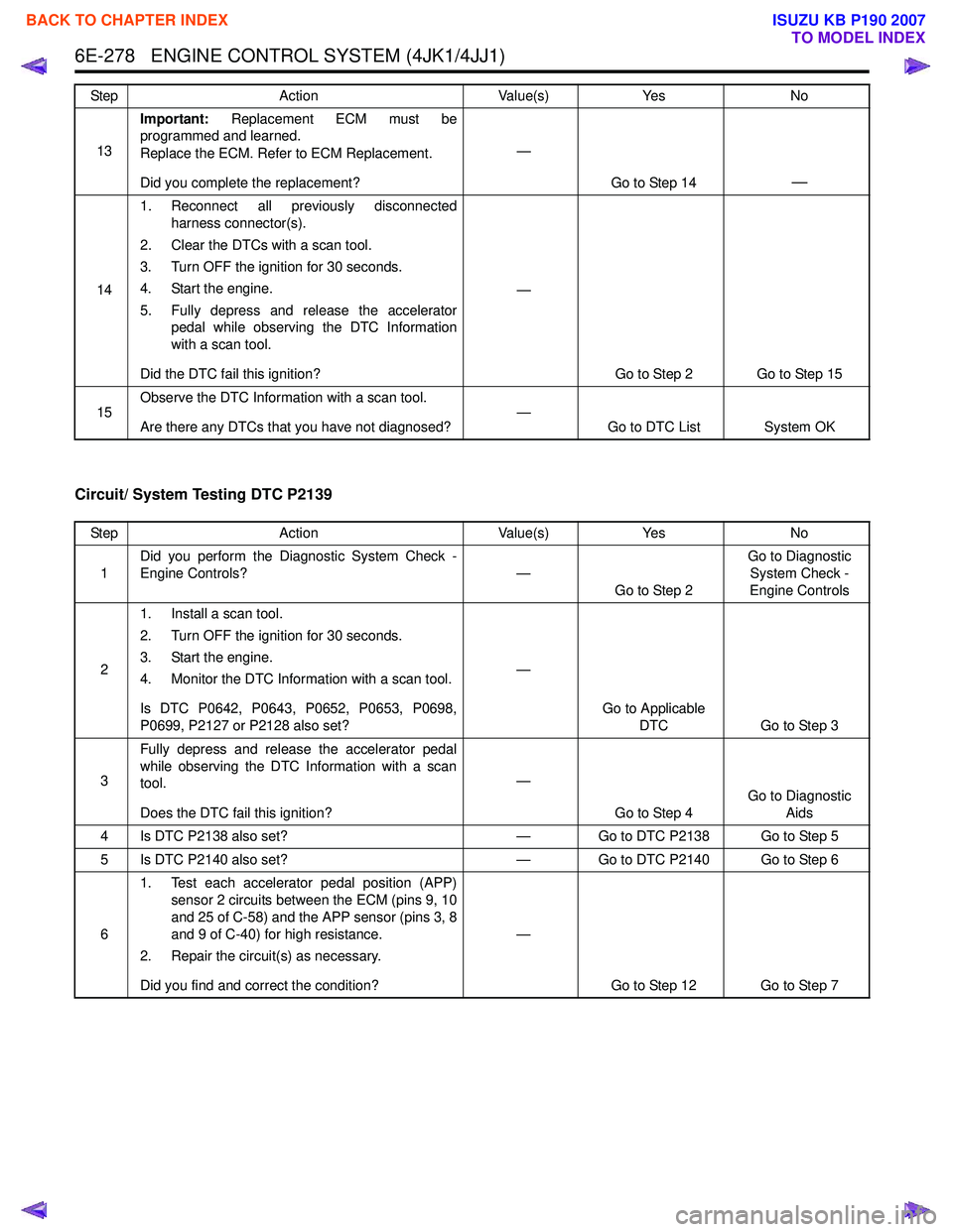
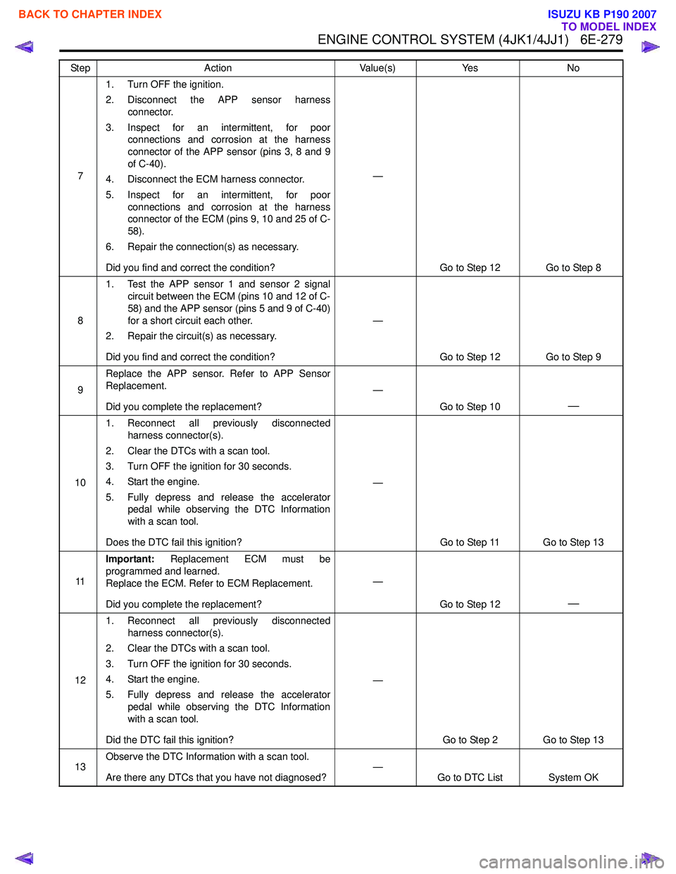
Circuit/ System Testing DTC P2139
13Important:
Replacement ECM must be
programmed and learned.
Replace the ECM. Refer to ECM Replacement.
Did you complete the replacement? —
Go to Step 14
—
141. Reconnect all previously disconnected
harness connector(s).
2. Clear the DTCs with a scan tool.
3. Turn OFF the ignition for 30 seconds.
4. Start the engine.
5. Fully depress and release the accelerator pedal while observing the DTC Information
with a scan tool.
Did the DTC fail this ignition? —
Go to Step 2 Go to Step 15
15 Observe the DTC Information with a scan tool.
Are there any DTCs that you have not diagnosed? —
Go to DTC List System OK
Step
Action Value(s)Yes No
Step Action Value(s)Yes No
1 Did you perform the Diagnostic System Check -
Engine Controls? —
Go to Step 2 Go to Diagnostic
System Check -
Engine Controls
2 1. Install a scan tool.
2. Turn OFF the ignition for 30 seconds.
3. Start the engine.
4. Monitor the DTC Information with a scan tool.
Is DTC P0642, P0643, P0652, P0653, P0698,
P0699, P2127 or P2128 also set? —
Go to Applicable DTC Go to Step 3
3 Fully depress and release the accelerator pedal
while observing the DTC Information with a scan
tool.
Does the DTC fail this ignition? —
Go to Step 4 Go to Diagnostic
Aids
4 Is DTC P2138 also set? — Go to DTC P2138 Go to Step 5
5 Is DTC P2140 also set? — Go to DTC P2140 Go to Step 6
6 1. Test each accelerator pedal position (APP)
sensor 2 circuits between the ECM (pins 9, 10
and 25 of C-58) and the APP sensor (pins 3, 8
and 9 of C-40) for high resistance.
2. Repair the circuit(s) as necessary.
Did you find and correct the condition? —
Go to Step 12 Go to Step 7
BACK TO CHAPTER INDEX
TO MODEL INDEX
ISUZU KB P190 2007
Page 1896 of 6020
ENGINE CONTROL SYSTEM (4JK1/4JJ1) 6E-279
71. Turn OFF the ignition.
2. Disconnect the APP sensor harness connector.
3. Inspect for an intermittent, for poor connections and corrosion at the harness
connector of the APP sensor (pins 3, 8 and 9
of C-40).
4. Disconnect the ECM harness connector.
5. Inspect for an intermittent, for poor connections and corrosion at the harness
connector of the ECM (pins 9, 10 and 25 of C-
58).
6. Repair the connection(s) as necessary.
Did you find and correct the condition? —
Go to Step 12 Go to Step 8
8 1. Test the APP sensor 1 and sensor 2 signal
circuit between the ECM (pins 10 and 12 of C-
58) and the APP sensor (pins 5 and 9 of C-40)
for a short circuit each other.
2. Repair the circuit(s) as necessary.
Did you find and correct the condition? —
Go to Step 12 Go to Step 9
9 Replace the APP sensor. Refer to APP Sensor
Replacement.
Did you complete the replacement? —
Go to Step 10
—
101. Reconnect all previously disconnected
harness connector(s).
2. Clear the DTCs with a scan tool.
3. Turn OFF the ignition for 30 seconds.
4. Start the engine.
5. Fully depress and release the accelerator pedal while observing the DTC Information
with a scan tool.
Does the DTC fail this ignition? —
Go to Step 11 Go to Step 13
11 Important:
Replacement ECM must be
programmed and learned.
Replace the ECM. Refer to ECM Replacement.
Did you complete the replacement? —
Go to Step 12
—
121. Reconnect all previously disconnected
harness connector(s).
2. Clear the DTCs with a scan tool.
3. Turn OFF the ignition for 30 seconds.
4. Start the engine.
5. Fully depress and release the accelerator pedal while observing the DTC Information
with a scan tool.
Did the DTC fail this ignition? —
Go to Step 2 Go to Step 13
13 Observe the DTC Information with a scan tool.
Are there any DTCs that you have not diagnosed? —
Go to DTC List System OK
Step
Action Value(s)Yes No
BACK TO CHAPTER INDEX
TO MODEL INDEX
ISUZU KB P190 2007
Page 1897 of 6020
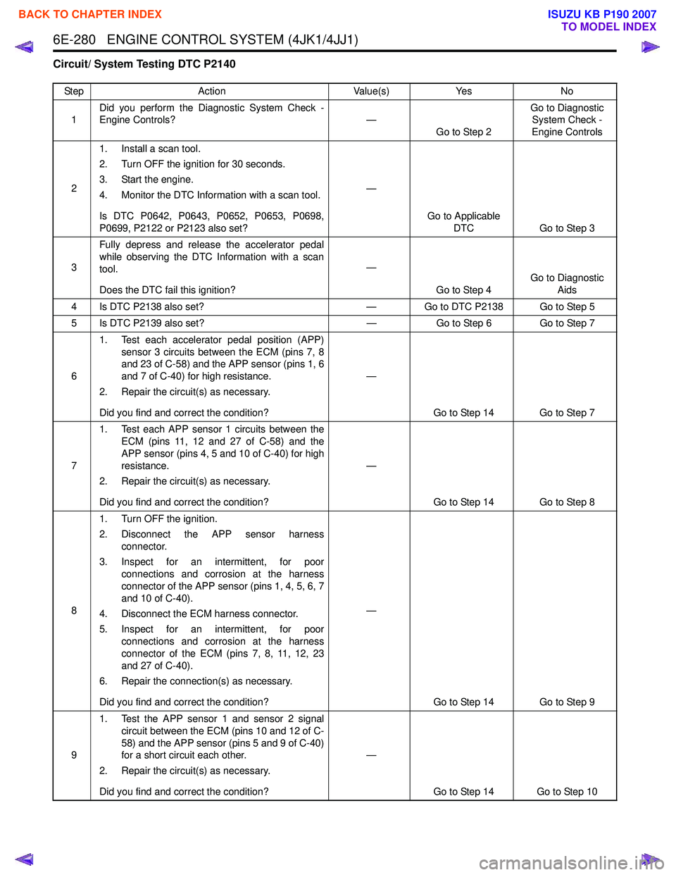
6E-280 ENGINE CONTROL SYSTEM (4JK1/4JJ1)
Circuit/ System Testing DTC P2140
StepAction Value(s)Yes No
1 Did you perform the Diagnostic System Check -
Engine Controls? —
Go to Step 2 Go to Diagnostic
System Check -
Engine Controls
2 1. Install a scan tool.
2. Turn OFF the ignition for 30 seconds.
3. Start the engine.
4. Monitor the DTC Information with a scan tool.
Is DTC P0642, P0643, P0652, P0653, P0698,
P0699, P2122 or P2123 also set? —
Go to Applicable DTC Go to Step 3
3 Fully depress and release the accelerator pedal
while observing the DTC Information with a scan
tool.
Does the DTC fail this ignition? —
Go to Step 4 Go to Diagnostic
Aids
4 Is DTC P2138 also set? — Go to DTC P2138 Go to Step 5
5 Is DTC P2139 also set? —Go to Step 6 Go to Step 7
6 1. Test each accelerator pedal position (APP)
sensor 3 circuits between the ECM (pins 7, 8
and 23 of C-58) and the APP sensor (pins 1, 6
and 7 of C-40) for high resistance.
2. Repair the circuit(s) as necessary.
Did you find and correct the condition? —
Go to Step 14 Go to Step 7
7 1. Test each APP sensor 1 circuits between the
ECM (pins 11, 12 and 27 of C-58) and the
APP sensor (pins 4, 5 and 10 of C-40) for high
resistance.
2. Repair the circuit(s) as necessary.
Did you find and correct the condition? —
Go to Step 14 Go to Step 8
8 1. Turn OFF the ignition.
2. Disconnect the APP sensor harness connector.
3. Inspect for an intermittent, for poor connections and corrosion at the harness
connector of the APP sensor (pins 1, 4, 5, 6, 7
and 10 of C-40).
4. Disconnect the ECM harness connector.
5. Inspect for an intermittent, for poor connections and corrosion at the harness
connector of the ECM (pins 7, 8, 11, 12, 23
and 27 of C-40).
6. Repair the connection(s) as necessary.
Did you find and correct the condition? —
Go to Step 14 Go to Step 9
9 1. Test the APP sensor 1 and sensor 2 signal
circuit between the ECM (pins 10 and 12 of C-
58) and the APP sensor (pins 5 and 9 of C-40)
for a short circuit each other.
2. Repair the circuit(s) as necessary.
Did you find and correct the condition? —
Go to Step 14 Go to Step 10
BACK TO CHAPTER INDEX
TO MODEL INDEX
ISUZU KB P190 2007
Page 1898 of 6020
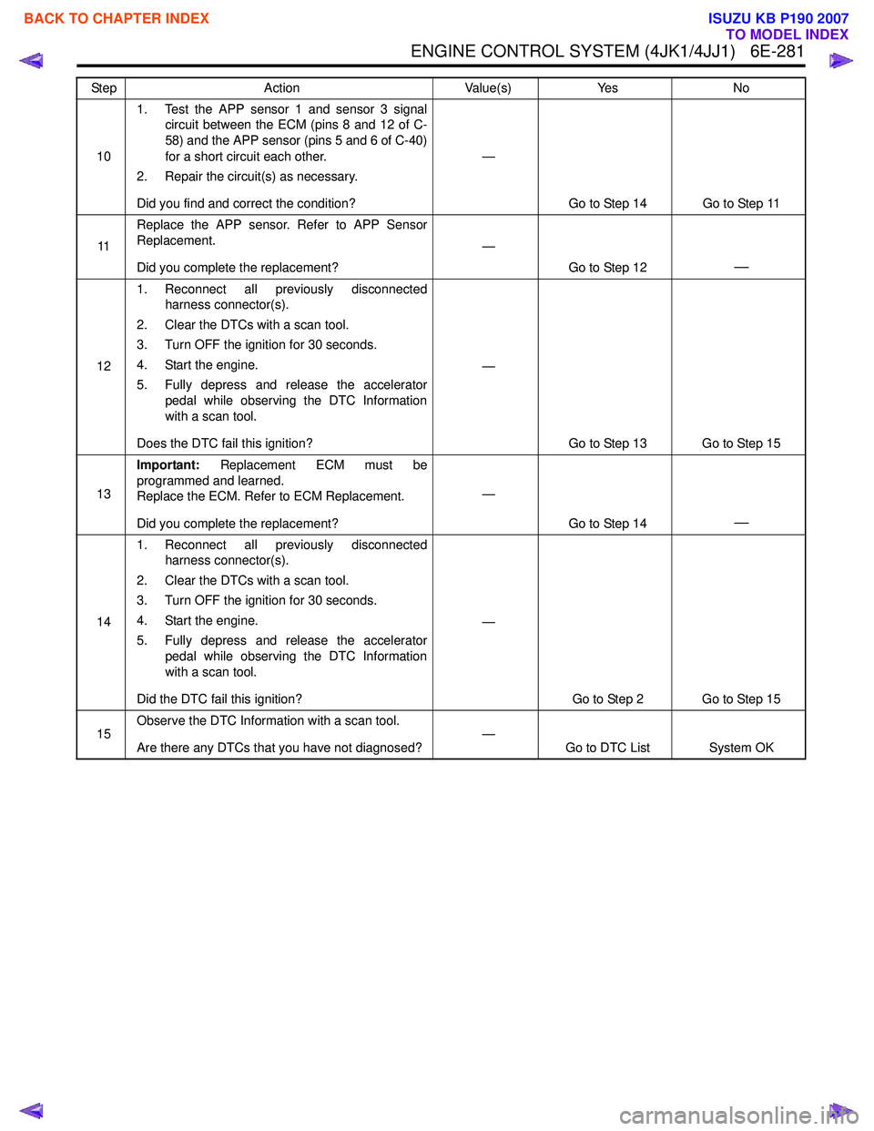
ENGINE CONTROL SYSTEM (4JK1/4JJ1) 6E-281
101. Test the APP sensor 1 and sensor 3 signal
circuit between the ECM (pins 8 and 12 of C-
58) and the APP sensor (pins 5 and 6 of C-40)
for a short circuit each other.
2. Repair the circuit(s) as necessary.
Did you find and correct the condition? —
Go to Step 14 Go to Step 11
11 Replace the APP sensor. Refer to APP Sensor
Replacement.
Did you complete the replacement? —
Go to Step 12
—
121. Reconnect all previously disconnected
harness connector(s).
2. Clear the DTCs with a scan tool.
3. Turn OFF the ignition for 30 seconds.
4. Start the engine.
5. Fully depress and release the accelerator pedal while observing the DTC Information
with a scan tool.
Does the DTC fail this ignition? —
Go to Step 13 Go to Step 15
13 Important:
Replacement ECM must be
programmed and learned.
Replace the ECM. Refer to ECM Replacement.
Did you complete the replacement? —
Go to Step 14
—
141. Reconnect all previously disconnected
harness connector(s).
2. Clear the DTCs with a scan tool.
3. Turn OFF the ignition for 30 seconds.
4. Start the engine.
5. Fully depress and release the accelerator pedal while observing the DTC Information
with a scan tool.
Did the DTC fail this ignition? —
Go to Step 2 Go to Step 15
15 Observe the DTC Information with a scan tool.
Are there any DTCs that you have not diagnosed? —
Go to DTC List System OK
Step Action Value(s) Yes No
BACK TO CHAPTER INDEX
TO MODEL INDEX
ISUZU KB P190 2007
Page 1899 of 6020
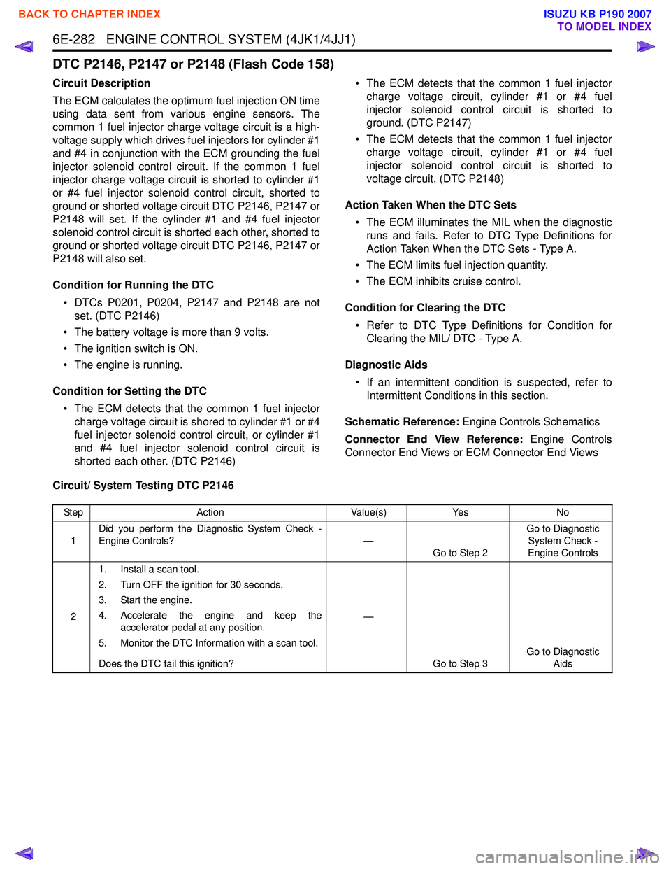
6E-282 ENGINE CONTROL SYSTEM (4JK1/4JJ1)
DTC P2146, P2147 or P2148 (Flash Code 158)
Circuit Description
The ECM calculates the optimum fuel injection ON time
using data sent from various engine sensors. The
common 1 fuel injector charge voltage circuit is a high-
voltage supply which drives fuel injectors for cylinder #1
and #4 in conjunction with the ECM grounding the fuel
injector solenoid control circuit. If the common 1 fuel
injector charge voltage circuit is shorted to cylinder #1
or #4 fuel injector solenoid control circuit, shorted to
ground or shorted voltage circuit DTC P2146, P2147 or
P2148 will set. If the cylinder #1 and #4 fuel injector
solenoid control circuit is shorted each other, shorted to
ground or shorted voltage circuit DTC P2146, P2147 or
P2148 will also set.
Condition for Running the DTC • DTCs P0201, P0204, P2147 and P2148 are not set. (DTC P2146)
• The battery voltage is more than 9 volts.
• The ignition switch is ON.
• The engine is running.
Condition for Setting the DTC • The ECM detects that the common 1 fuel injector charge voltage circuit is shored to cylinder #1 or #4
fuel injector solenoid control circuit, or cylinder #1
and #4 fuel injector solenoid control circuit is
shorted each other. (DTC P2146) • The ECM detects that the common 1 fuel injector
charge voltage circuit, cylinder #1 or #4 fuel
injector solenoid control circuit is shorted to
ground. (DTC P2147)
• The ECM detects that the common 1 fuel injector charge voltage circuit, cylinder #1 or #4 fuel
injector solenoid control circuit is shorted to
voltage circuit. (DTC P2148)
Action Taken When the DTC Sets • The ECM illuminates the MIL when the diagnostic runs and fails. Refer to DTC Type Definitions for
Action Taken When the DTC Sets - Type A.
• The ECM limits fuel injection quantity.
• The ECM inhibits cruise control.
Condition for Clearing the DTC • Refer to DTC Type Definitions for Condition for Clearing the MIL/ DTC - Type A.
Diagnostic Aids • If an intermittent condition is suspected, refer to Intermittent Conditions in this section.
Schematic Reference: Engine Controls Schematics
Connector End View Reference: Engine Controls
Connector End Views or ECM Connector End Views
Circuit/ System Testing DTC P2146
Step Action Value(s)Yes No
1 Did you perform the Diagnostic System Check -
Engine Controls? —
Go to Step 2 Go to Diagnostic
System Check -
Engine Controls
2 1. Install a scan tool.
2. Turn OFF the ignition for 30 seconds.
3. Start the engine.
4. Accelerate the engine and keep the accelerator pedal at any position.
5. Monitor the DTC Information with a scan tool.
Does the DTC fail this ignition? —
Go to Step 3 Go to Diagnostic
Aids
BACK TO CHAPTER INDEX
TO MODEL INDEX
ISUZU KB P190 2007
Page 1900 of 6020
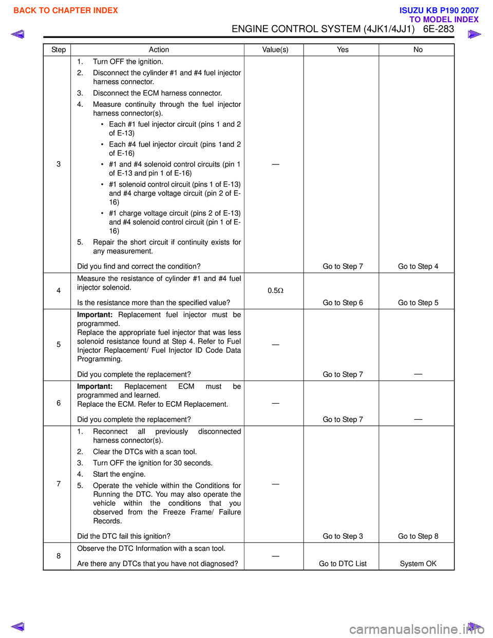
ENGINE CONTROL SYSTEM (4JK1/4JJ1) 6E-283
31. Turn OFF the ignition.
2. Disconnect the cylinder #1 and #4 fuel injector harness connector.
3. Disconnect the ECM harness connector.
4. Measure continuity through the fuel injector harness connector(s).
• Each #1 fuel injector circuit (pins 1 and 2 of E-13)
• Each #4 fuel injector circuit (pins 1and 2 of E-16)
• #1 and #4 solenoid control circuits (pin 1 of E-13 and pin 1 of E-16)
• #1 solenoid control circuit (pins 1 of E-13) and #4 charge voltage circuit (pin 2 of E-
16)
• #1 charge voltage circuit (pins 2 of E-13) and #4 solenoid control circuit (pin 1 of E-
16)
5. Repair the short circuit if continuity exists for any measurement.
Did you find and correct the condition? —
Go to Step 7 Go to Step 4
4 Measure the resistance of cylinder #1 and #4 fuel
injector solenoid.
Is the resistance more than the specified value? 0.5
Ω
Go to Step 6 Go to Step 5
5 Important:
Replacement fuel injector must be
programmed.
Replace the appropriate fuel injector that was less
solenoid resistance found at Step 4. Refer to Fuel
Injector Replacement/ Fuel Injector ID Code Data
Programming.
Did you complete the replacement? —
Go to Step 7
—
6Important:
Replacement ECM must be
programmed and learned.
Replace the ECM. Refer to ECM Replacement.
Did you complete the replacement? —
Go to Step 7
—
71. Reconnect all previously disconnected
harness connector(s).
2. Clear the DTCs with a scan tool.
3. Turn OFF the ignition for 30 seconds.
4. Start the engine.
5. Operate the vehicle within the Conditions for Running the DTC. You may also operate the
vehicle within the conditions that you
observed from the Freeze Frame/ Failure
Records.
Did the DTC fail this ignition? —
Go to Step 3 Go to Step 8
8 Observe the DTC Information with a scan tool.
Are there any DTCs that you have not diagnosed? —
Go to DTC List System OK
Step
Action Value(s)Yes No
BACK TO CHAPTER INDEX
TO MODEL INDEX
ISUZU KB P190 2007