2007 ISUZU KB P190 coolant
[x] Cancel search: coolantPage 3682 of 6020
Powertrain Interface Module – V6 Page 6E1–21
6.3 Connector Information
PIM Connector Pin Specifications
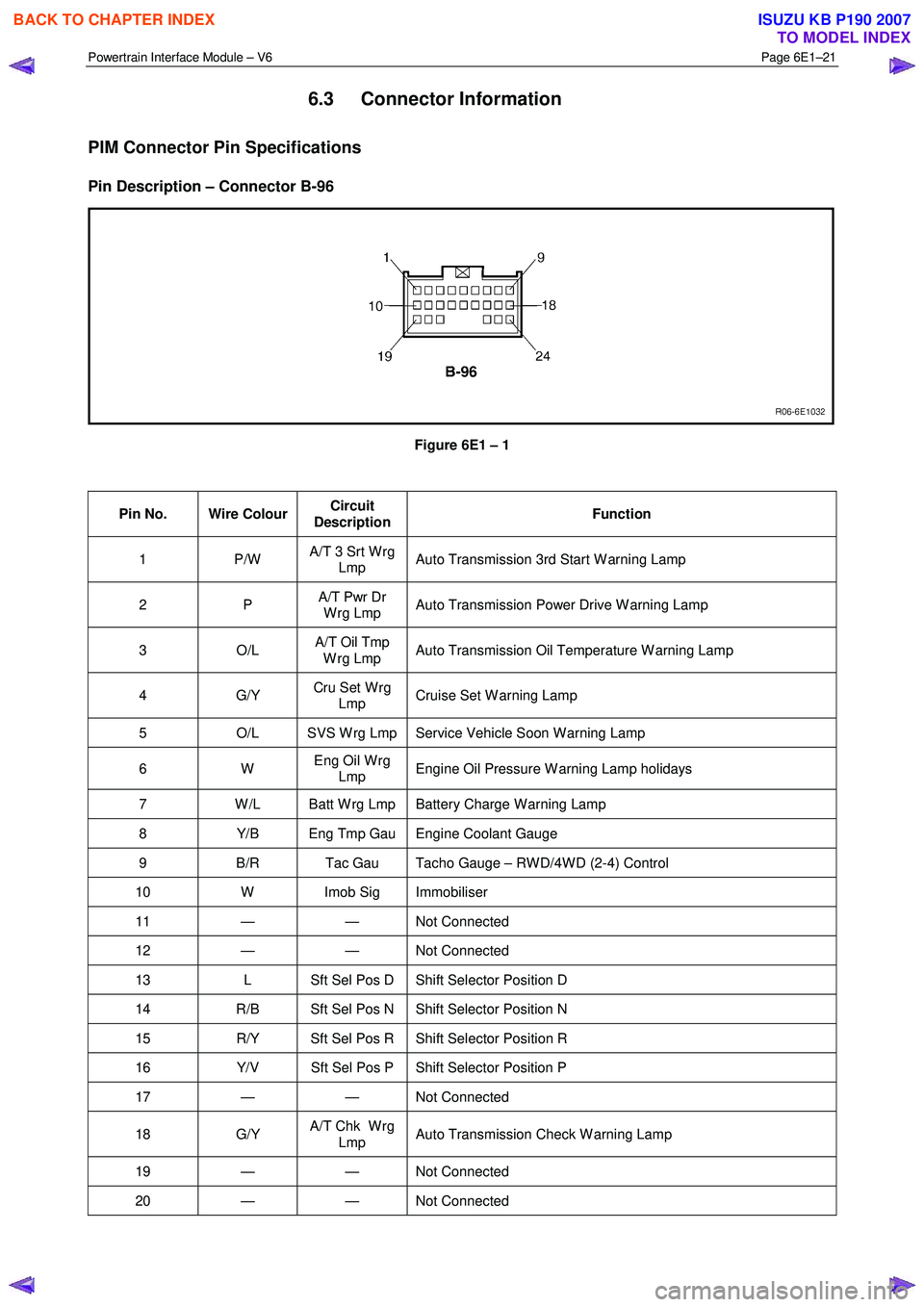
Pin Description – Connector B-96
Figure 6E1 – 1
Pin No. Wire Colour Circuit
Description Function
1 P/W
A/T 3 Srt W rg
Lmp Auto Transmission 3rd Start W arning Lamp
2 P
A/T Pwr Dr
W rg Lmp Auto Transmission Power Drive W arning Lamp
3 O/L A/T Oil Tmp
W rg Lmp Auto Transmission Oil Temperature W arning Lamp
4 G/Y
Cru Set W rg
Lmp Cruise Set W arning Lamp
5
O/L SVS W rg Lmp Service Vehicle Soon W arning Lamp
6 W Eng Oil W rg
Lmp Engine Oil Pressure W arning Lamp holidays
7
W /L Batt W rg Lmp Battery Charge W arning Lamp
8 Y/B Eng Tmp Gau Engine Coolant Gauge
9 B/R Tac Gau Tacho Gauge – RW D/4W D (2-4) Control
10 W Imob Sig Immobiliser
11 — — Not Connected
12 — — Not Connected
13 L Sft Sel Pos D Shift Selector Position D
14 R/B Sft Sel Pos N Shift Selector Position N
15 R/Y Sft Sel Pos R Shift Selector Position R
16 Y/V Sft Sel Pos P Shift Selector Position P
17 — — Not Connected
18 G/Y A/T Chk W rg
Lmp Auto Transmission Check W arning Lamp
19 — — Not
Connected
20 — — Not Connected
BACK TO CHAPTER INDEX
TO MODEL INDEX
ISUZU KB P190 2007
Page 3701 of 6020
Powertrain Interface Module – V6 Page 6E1–40
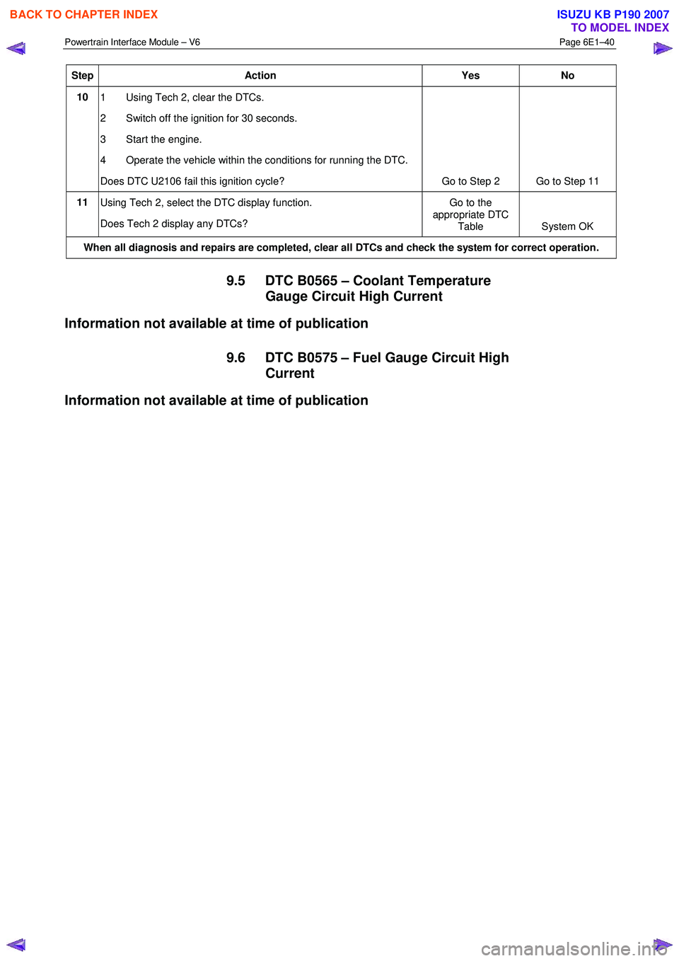
Step Action Yes No
10
1 Using Tech 2, clear the DTCs.
2 Switch off the ignition for 30 seconds.
3 Start the engine.
4 Operate the vehicle within the conditions for running the DTC.
Does DTC U2106 fail this ignition cycle? Go to Step 2 Go to Step 11
11
Using Tech 2, select the DTC display function.
Does Tech 2 display any DTCs? Go to the
appropriate DTC Table System OK
When all diagnosis and repairs are completed, clear all DTCs and check the system for correct operation.
9.5 DTC B0565 – Coolant Temperature
Gauge Circuit High Current
Information not available at time of publication
9.6 DTC B0575 – Fuel Gauge Circuit High Current
Information not available at time of publication
BACK TO CHAPTER INDEX
TO MODEL INDEX
ISUZU KB P190 2007
Page 3742 of 6020
Powertrain Interface Module – V6 Page 6E1–81
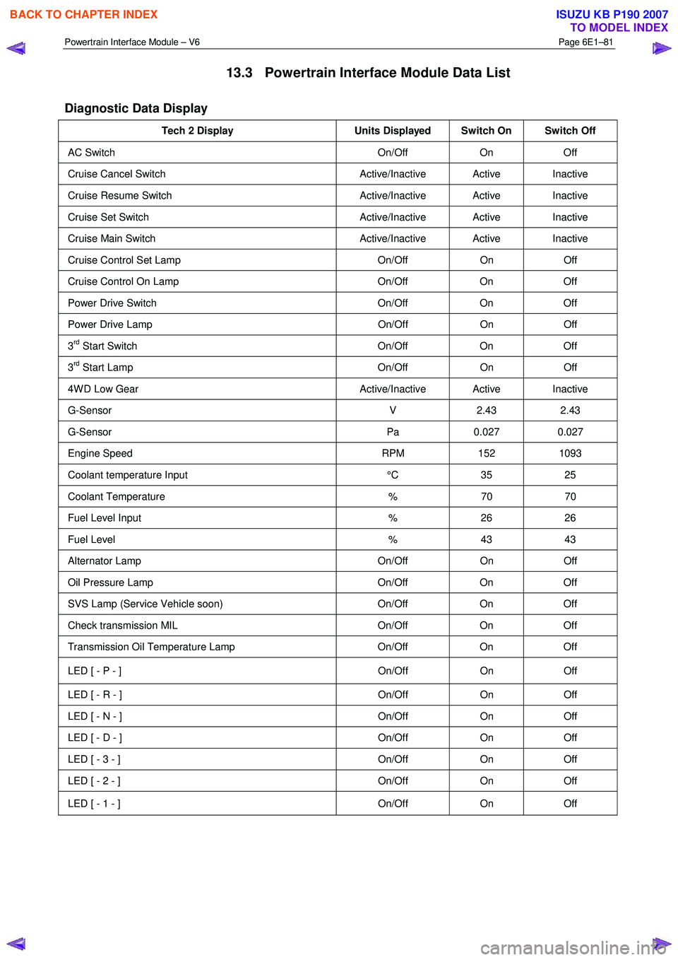
13.3 Powertrain Interface Module Data List
Diagnostic Data Display
Tech 2 Display Units Displayed Switch On Switch Off
AC Switch On/Off On Off
Cruise Cancel Switch Active/Inactive Active Inactive
Cruise Resume Switch Active/Inactive Active Inactive
Cruise Set Switch Active/Inactive Active Inactive
Cruise Main Switch Active/Inactive Active Inactive
Cruise Control Set Lamp On/Off On Off
Cruise Control On Lamp On/Off On Off
Power Drive Switch On/Off On Off
Power Drive Lamp On/Off On Off
3rd Start Switch On/Off On Off
3rd Start Lamp On/Off On Off
4W D Low Gear Active/Inactive Active Inactive
G-Sensor V 2.43 2.43
G-Sensor Pa 0.027 0.027
Engine Speed RPM 152 1093
Coolant temperature Input °C 35 25
Coolant Temperature % 70 70
Fuel Level Input % 26 26
Fuel Level % 43 43
Alternator Lamp On/Off On Off
Oil Pressure Lamp On/Off On Off
SVS Lamp (Service Vehicle soon) On/Off On Off
Check transmission MIL On/Off On Off
Transmission Oil Temperature Lamp On/Off On Off
LED [ - P - ] On/Off On Off
LED [ - R - ] On/Off On Off
LED [ - N - ] On/Off On Off
LED [ - D - ] On/Off On Off
LED [ - 3 - ] On/Off On Off
LED [ - 2 - ] On/Off On Off
LED [ - 1 - ] On/Off On Off
BACK TO CHAPTER INDEX
TO MODEL INDEX
ISUZU KB P190 2007
Page 3754 of 6020
Exhaust System – V6 Page 6F – 6
• Faulty operation or performance of any system or component being repaired,
• Damage to any system or components which depend on the proper operation of the system or component being
repaired,
• Faulty operation or performance of any systems or components which depend on the proper operation or
performance of the system or component under repair,
• Damage to fasteners, basic tools or special tools and / or
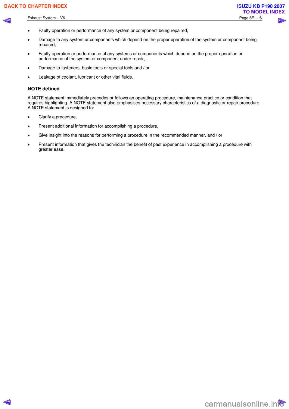
• Leakage of coolant, lubricant or other vital fluids.
NOTE defined
A NOTE statement immediately precedes or follows an operating procedure, maintenance practice or condition that
requires highlighting. A NOTE statement also emphasises necessary characteristics of a diagnostic or repair procedure.
A NOTE statement is designed to:
• Clarify a procedure,
• Present additional information for accomplishing a procedure,
• Give insight into the reasons for performing a procedure in the recommended manner, and / or
• Present information that gives the technician the benefit of past experience in accomplishing a procedure with
greater ease.
BACK TO CHAPTER INDEX
TO MODEL INDEX
ISUZU KB P190 2007
Page 3763 of 6020
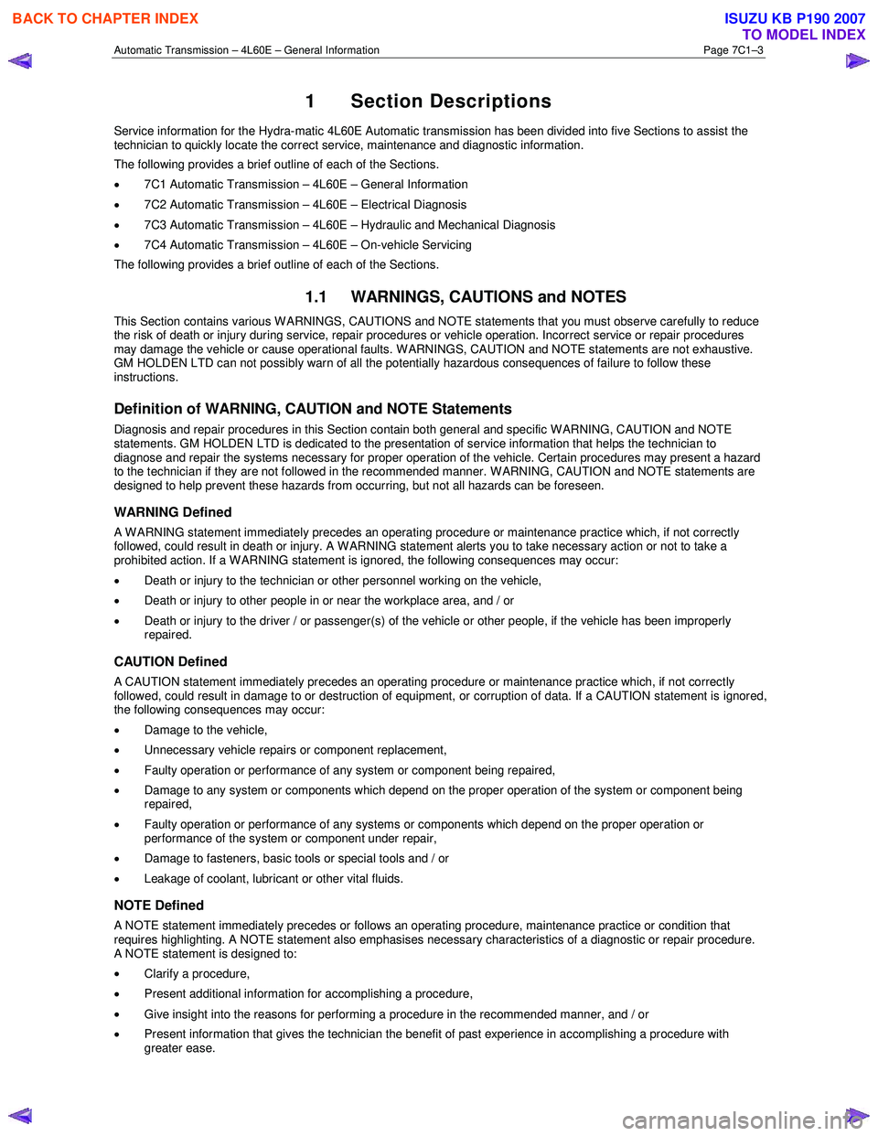
Automatic Transmission – 4L60E – General Information Page 7C1–3
1 Section Descriptions
Service information for the Hydra-matic 4L60E Automatic transmission has been divided into five Sections to assist the
technician to quickly locate the correct service, maintenance and diagnostic information.
The following provides a brief outline of each of the Sections.
• 7C1 Automatic Transmission – 4L60E – General Information
• 7C2 Automatic Transmission – 4L60E – Electrical Diagnosis
• 7C3 Automatic Transmission – 4L60E – Hydraulic and Mechanical Diagnosis
• 7C4 Automatic Transmission – 4L60E – On-vehicle Servicing
The following provides a brief outline of each of the Sections.
1.1 WARNINGS, CAUTIONS and NOTES
This Section contains various W ARNINGS, CAUTIONS and NOTE statements that you must observe carefully to reduce
the risk of death or injury during service, repair procedures or vehicle operation. Incorrect service or repair procedures
may damage the vehicle or cause operational faults. W ARNINGS, CAUTION and NOTE statements are not exhaustive.
GM HOLDEN LTD can not possibly warn of all the potentially hazardous consequences of failure to follow these
instructions.
Definition of WARNING, CAUTION and NOTE Statements
Diagnosis and repair procedures in this Section contain both general and specific W ARNING, CAUTION and NOTE
statements. GM HOLDEN LTD is dedicated to the presentation of service information that helps the technician to
diagnose and repair the systems necessary for proper operation of the vehicle. Certain procedures may present a hazard
to the technician if they are not followed in the recommended manner. W ARNING, CAUTION and NOTE statements are
designed to help prevent these hazards from occurring, but not all hazards can be foreseen.
WARNING Defined
A W ARNING statement immediately precedes an operating procedure or maintenance practice which, if not correctly
followed, could result in death or injury. A WARNING statement alerts you to take necessary action or not to take a
prohibited action. If a W ARNING statement is ignored, the following consequences may occur:
• Death or injury to the technician or other personnel working on the vehicle,
• Death or injury to other people in or near the workplace area, and / or
• Death or injury to the driver / or passenger(s) of the vehicle or other people, if the vehicle has been improperly
repaired.
CAUTION Defined
A CAUTION statement immediately precedes an operating procedure or maintenance practice which, if not correctly
followed, could result in damage to or destruction of equipment, or corruption of data. If a CAUTION statement is ignored,
the following consequences may occur:
• Damage to the vehicle,
• Unnecessary vehicle repairs or component replacement,
• Faulty operation or performance of any system or component being repaired,
• Damage to any system or components which depend on the proper operation of the system or component being
repaired,
• Faulty operation or performance of any systems or components which depend on the proper operation or
performance of the system or component under repair,
• Damage to fasteners, basic tools or special tools and / or
• Leakage of coolant, lubricant or other vital fluids.
NOTE Defined
A NOTE statement immediately precedes or follows an operating procedure, maintenance practice or condition that
requires highlighting. A NOTE statement also emphasises necessary characteristics of a diagnostic or repair procedure.
A NOTE statement is designed to:
• Clarify a procedure,
• Present additional information for accomplishing a procedure,
• Give insight into the reasons for performing a procedure in the recommended manner, and / or
• Present information that gives the technician the benefit of past experience in accomplishing a procedure with
greater ease.
BACK TO CHAPTER INDEX
TO MODEL INDEX
ISUZU KB P190 2007
Page 3774 of 6020
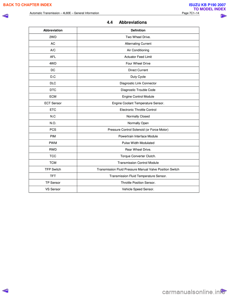
Automatic Transmission – 4L60E – General Information Page 7C1–14
4.4 Abbreviations
Abbreviation Definition
2W D Two W heel Drive.
AC Alternating Current
A/C Air Conditioning
AFL Actuator Feed Limit
4W D Four W heel Drive
DC Direct Current
D.C Duty Cycle
DLC Diagnostic Link Connector
DTC Diagnostic Trouble Code
ECM Engine Control Module
ECT Sensor Engine Coolant Temperature Sensor.
ETC Electronic Throttle Control
N.C Normally Closed
N.O. Normally Open
PCS Pressure Control Solenoid (or Force Motor)
PIM Powertrain Interface Module
PW M Pulse W idth Modulated
RWD Rear Wheel Drive.
TCC Torque Converter Clutch.
TCM Transmission Control Module
TFP Switch Transmission Fluid Pressure Manual Valve Position Switch
TFT Transmission Fluid Temperature Sensor.
TP Sensor Throttle Position Sensor.
VS Sensor Vehicle Speed Sensor.
BACK TO CHAPTER INDEX
TO MODEL INDEX
ISUZU KB P190 2007
Page 3777 of 6020
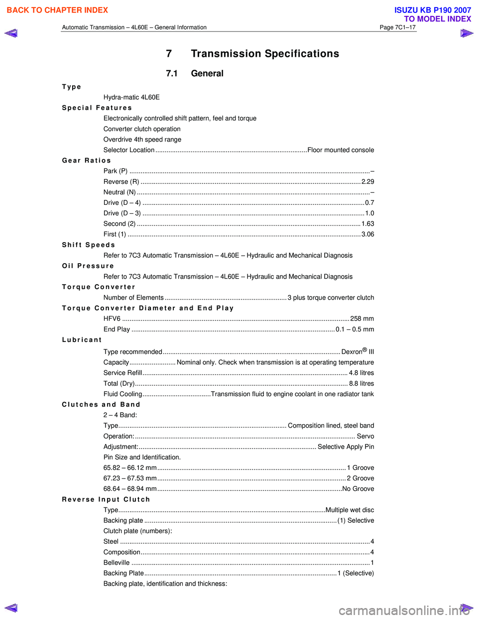
Automatic Transmission – 4L60E – General Information Page 7C1–17
7 Transmission Specifications
7.1 General
Type
Hydra-matic 4L60E
Special Features
Electronically controlled shift pattern, feel and torque
Converter clutch operation
Overdrive 4th speed range
Selector Location ..................................................................................Floor mounted console
Gear Ratios Park (P) ....................................................................................................................... ........... –
Reverse (R) .................................................................................................................... ... 2.29
Neutral (N) .............................................................................................................................. –
Drive (D – 4) .................................................................................................................. ...... 0.7
Drive (D – 3) .................................................................................................................. ...... 1.0
Second (2) ......................................................................................................................... 1.63
First (1) ...................................................................................................................... ........ 3.06
Shift Speeds Refer to 7C3 Automatic Transmission – 4L60E – Hydraulic and Mechanical Diagnosis
Oil Pressure
Refer to 7C3 Automatic Transmission – 4L60E – Hydraulic and Mechanical Diagnosis
Torque Converter
Number of Elements .................................................................. 3 plus torque converter clutch
Torque Converter Diameter and End Play
HFV6 ........................................................................................................................... 258 mm
End Play .............................................................................................................. 0.1 – 0.5 mm
Lubricant
Type recommended ................................................................................................ Dexron
® III
Capacity......................... Nominal only. Check when transmission is at operating temperature
Service Refill ............................................................................................................... 4. 8 litres
Total (Dry)................................................................................................................... 8 .8 litres
Fluid Cooling.....................................Transmission fluid to engine coolant in one radiator tank
Clutches and Band 2 – 4 Band:
Type........................................................................................... Composition lined, steel band
Operation: ..................................................................................................................... .. Servo
Adjustment: ................................................................................................ Selective Apply Pin
Pin Size and Identification.
65.82 – 66.12 mm ...................................................................................................... 1 Groove
67.23 – 67.53 mm ...................................................................................................... 2 Groove
68.64 – 68.94 mm ....................................................................................................No Groove
Reverse Input Clutch Type................................................................................................................Multiple we t disc
Backing plate ........................................................................................................ (1) Select ive
Clutch plate (numbers):
Steel ....................................................................................................................................... 4
Composition............................................................................................................................ 4
Belleville ..................................................................................................................... ............ 1
Backing Plate ........................................................................................................ 1 (Selecti ve)
Backing plate, identification and thickness:
BACK TO CHAPTER INDEX
TO MODEL INDEX
ISUZU KB P190 2007
Page 3794 of 6020
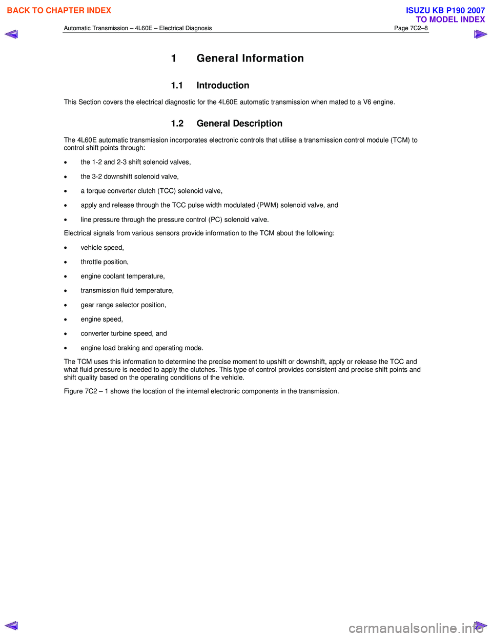
Automatic Transmission – 4L60E – Electrical Diagnosis Page 7C2–8
1 General Information
1.1 Introduction
This Section covers the electrical diagnostic for the 4L60E automatic transmission when mated to a V6 engine.
1.2 General Description
The 4L60E automatic transmission incorporates electronic controls that utilise a transmission control module (TCM) to
control shift points through:
• the 1-2 and 2-3 shift solenoid valves,
• the 3-2 downshift solenoid valve,
• a torque converter clutch (TCC) solenoid valve,
• apply and release through the TCC pulse width modulated (PW M) solenoid valve, and
• line pressure through the pressure control (PC) solenoid valve.
Electrical signals from various sensors provide information to the TCM about the following:
• vehicle speed,
• throttle position,
• engine coolant temperature,
• transmission fluid temperature,
• gear range selector position,
• engine speed,
• converter turbine speed, and
• engine load braking and operating mode.
The TCM uses this information to determine the precise moment to upshift or downshift, apply or release the TCC and
what fluid pressure is needed to apply the clutches. This type of control provides consistent and precise shift points and
shift quality based on the operating conditions of the vehicle.
Figure 7C2 – 1 shows the location of the internal electronic components in the transmission.
BACK TO CHAPTER INDEX
TO MODEL INDEX
ISUZU KB P190 2007