2007 ISUZU KB P190 engine coolant
[x] Cancel search: engine coolantPage 3581 of 6020
Engine Management – V6 – Service Operations Page 6C1-3–57
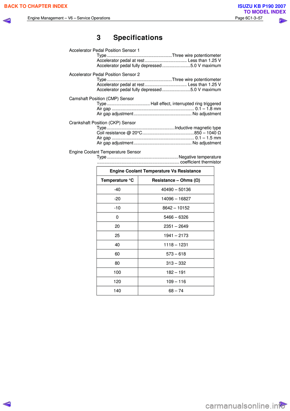
3 Specifications
Accelerator Pedal Position Sensor 1
Type .....................................................Three wire potentiometer
Accelerator pedal at rest .................................. Less than 1.25 V
Accelerator pedal fully depressed .......................5.0 V maximum
Accelerator Pedal Position Sensor 2
Type .....................................................Three wire potentiometer
Accelerator pedal at rest .................................. Less than 1.25 V
Accelerator pedal fully depressed .......................5.0 V maximum
Camshaft Position (CMP) Sensor
Type ................................... Hall effect, interrupted ring triggered
Air gap ................................................................... 0.1 – 1.8 mm
Air gap adjustment ............................................... No adjustment
Crankshaft Position (CKP) Sensor
Type ....................................................... Inductive magnetic type
Coil resistance @ 20°C .......................................... 850 – 1040 Ω
Air gap ................................................................... 0.1 – 1.5 mm
Air gap adjustment ............................................... No adjustment
Engine Coolant Temperature Sensor
Type .......................................................... Negative temperature
................................................................... coefficient thermistor
Engine Coolant Temperature Vs Resistance
Temperature °C Resistance – Ohms ( Ω)
-40 40490 – 50136
-20 14096 – 16827
-10 8642 – 10152
0 5466 – 6326
20 2351 – 2649
25 1941 – 2173
40 1118 – 1231
60 573 – 618
80 313 – 332
100 182 – 191
120 109 – 116
140 68 – 74
BACK TO CHAPTER INDEX
TO MODEL INDEX
ISUZU KB P190 2007
Page 3585 of 6020
Engine Management – V6 – Service Operations Page 6C1-3–61
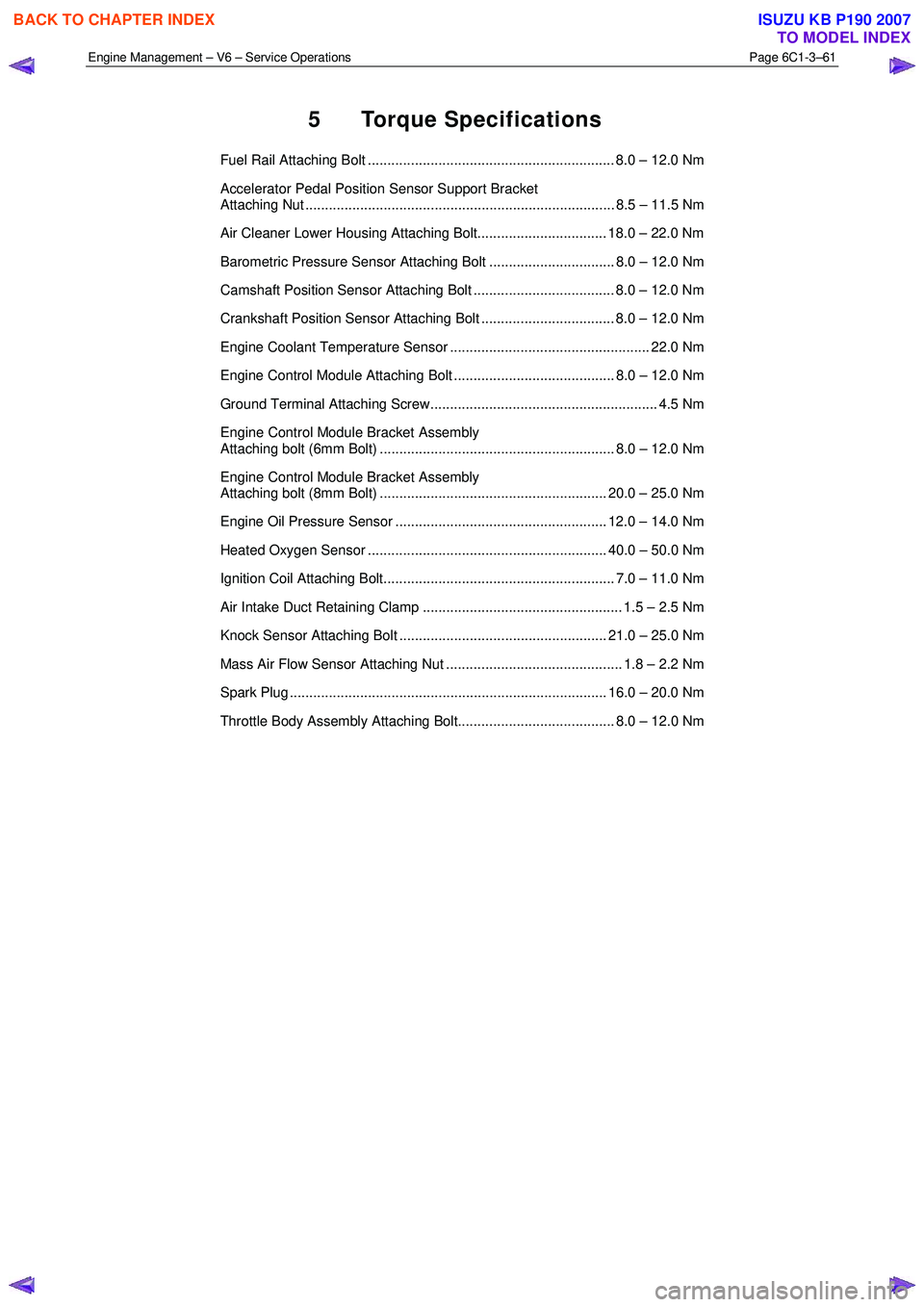
5 Torque Specifications
Fuel Rail Attaching Bolt ............................................................... 8.0 – 12.0 Nm
Accelerator Pedal Position Sensor Support Bracket
Attaching Nut ............................................................................... 8.5 – 11.5 Nm
Air Cleaner Lower Housing Attaching Bolt................................. 18.0 – 22.0 Nm
Barometric Pressure Sensor Attaching Bolt ................................ 8.0 – 12.0 Nm
Camshaft Position Sensor Attaching Bolt .................................... 8.0 – 12.0 Nm
Crankshaft Position Sensor Attaching Bolt .................................. 8.0 – 12.0 Nm
Engine Coolant Temperature Sensor ................................................... 22.0 Nm
Engine Control Module Attaching Bolt ......................................... 8.0 – 12.0 Nm
Ground Terminal Attaching Screw.......................................................... 4.5 Nm
Engine Control Module Bracket Assembly
Attaching bolt (6mm Bolt) ............................................................ 8.0 – 12.0 Nm
Engine Control Module Bracket Assembly
Attaching bolt (8mm Bolt) .......................................................... 20.0 – 25.0 Nm
Engine Oil Pressure Sensor ...................................................... 12.0 – 14.0 Nm
Heated Oxygen Sensor ............................................................. 40.0 – 50.0 Nm
Ignition Coil Attaching Bolt........................................................... 7.0 – 11.0 Nm
Air Intake Duct Retaining Clamp ................................................... 1.5 – 2.5 Nm
Knock Sensor Attaching Bolt ..................................................... 21.0 – 25.0 Nm
Mass Air Flow Sensor Attaching Nut ............................................. 1.8 – 2.2 Nm
Spark Plug ................................................................................. 16.0 – 20.0 Nm
Throttle Body Assembly Attaching Bolt........................................ 8.0 – 12.0 Nm
BACK TO CHAPTER INDEX
TO MODEL INDEX
ISUZU KB P190 2007
Page 3592 of 6020
Charging System – V6 Page 6D1-1-5
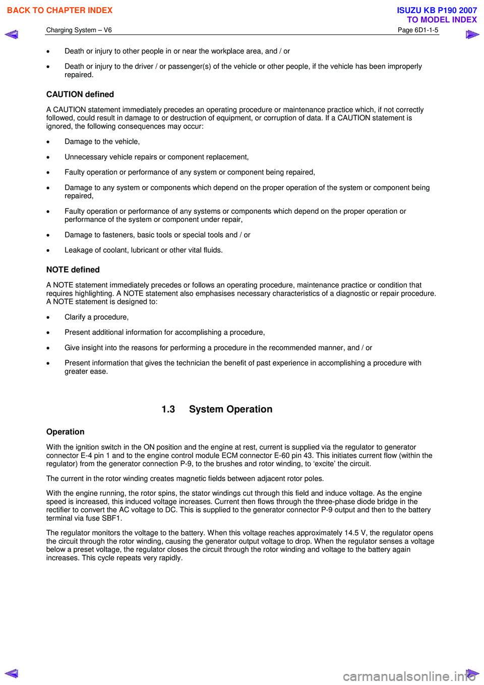
• Death or injury to other people in or near the workplace area, and / or
• Death or injury to the driver / or passenger(s) of the vehicle or other people, if the vehicle has been improperly
repaired.
CAUTION defined
A CAUTION statement immediately precedes an operating procedure or maintenance practice which, if not correctly
followed, could result in damage to or destruction of equipment, or corruption of data. If a CAUTION statement is
ignored, the following consequences may occur:
• Damage to the vehicle,
• Unnecessary vehicle repairs or component replacement,
• Faulty operation or performance of any system or component being repaired,
• Damage to any system or components which depend on the proper operation of the system or component being
repaired,
• Faulty operation or performance of any systems or components which depend on the proper operation or
performance of the system or component under repair,
• Damage to fasteners, basic tools or special tools and / or
• Leakage of coolant, lubricant or other vital fluids.
NOTE defined
A NOTE statement immediately precedes or follows an operating procedure, maintenance practice or condition that
requires highlighting. A NOTE statement also emphasises necessary characteristics of a diagnostic or repair procedure.
A NOTE statement is designed to:
• Clarify a procedure,
• Present additional information for accomplishing a procedure,
• Give insight into the reasons for performing a procedure in the recommended manner, and / or
• Present information that gives the technician the benefit of past experience in accomplishing a procedure with
greater ease.
1.3 System Operation
Operation
W ith the ignition switch in the ON position and the engine at rest, current is supplied via the regulator to generator
connector E-4 pin 1 and to the engine control module ECM connector E-60 pin 43. This initiates current flow (within the
regulator) from the generator connection P-9, to the brushes and rotor winding, to ‘excite’ the circuit.
The current in the rotor winding creates magnetic fields between adjacent rotor poles.
W ith the engine running, the rotor spins, the stator windings cut through this field and induce voltage. As the engine
speed is increased, this induced voltage increases. Current then flows through the three-phase diode bridge in the
rectifier to convert the AC voltage to DC. This is supplied to the generator connector P-9 output and then to the battery
terminal via fuse SBF1.
The regulator monitors the voltage to the battery. W hen this voltage reaches approximately 14.5 V, the regulator opens
the circuit through the rotor winding, causing the generator output voltage to drop. W hen the regulator senses a voltage
below a preset voltage, the regulator closes the circuit through the rotor winding and voltage to the battery again
increases. This cycle repeats very rapidly.
BACK TO CHAPTER INDEX
TO MODEL INDEX
ISUZU KB P190 2007
Page 3611 of 6020
Starting System – V6 Page 6D1-2–3
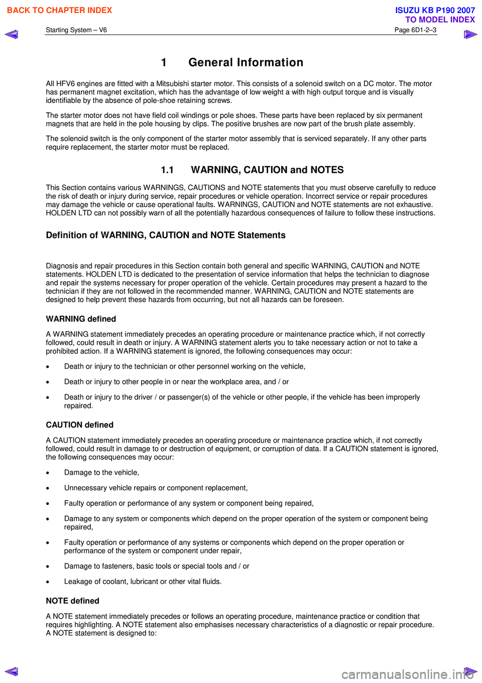
1 General Information
All HFV6 engines are fitted with a Mitsubishi starter motor. This consists of a solenoid switch on a DC motor. The motor
has permanent magnet excitation, which has the advantage of low weight a with high output torque and is visually
identifiable by the absence of pole-shoe retaining screws.
The starter motor does not have field coil windings or pole shoes. These parts have been replaced by six permanent
magnets that are held in the pole housing by clips. The positive brushes are now part of the brush plate assembly.
The solenoid switch is the only component of the starter motor assembly that is serviced separately. If any other parts
require replacement, the starter motor must be replaced.
1.1 WARNING, CAUTION and NOTES
This Section contains various W ARNINGS, CAUTIONS and NOTE statements that you must observe carefully to reduce
the risk of death or injury during service, repair procedures or vehicle operation. Incorrect service or repair procedures
may damage the vehicle or cause operational faults. W ARNINGS, CAUTION and NOTE statements are not exhaustive.
HOLDEN LTD can not possibly warn of all the potentially hazardous consequences of failure to follow these instructions.
Definition of WARNING, CAUTION and NOTE Statements
Diagnosis and repair procedures in this Section contain both general and specific W ARNING, CAUTION and NOTE
statements. HOLDEN LTD is dedicated to the presentation of service information that helps the technician to diagnose
and repair the systems necessary for proper operation of the vehicle. Certain procedures may present a hazard to the
technician if they are not followed in the recommended manner. W ARNING, CAUTION and NOTE statements are
designed to help prevent these hazards from occurring, but not all hazards can be foreseen.
WARNING defined
A W ARNING statement immediately precedes an operating procedure or maintenance practice which, if not correctly
followed, could result in death or injury. A W ARNING statement alerts you to take necessary action or not to take a
prohibited action. If a W ARNING statement is ignored, the following consequences may occur:
• Death or injury to the technician or other personnel working on the vehicle,
• Death or injury to other people in or near the workplace area, and / or
• Death or injury to the driver / or passenger(s) of the vehicle or other people, if the vehicle has been improperly
repaired.
CAUTION defined
A CAUTION statement immediately precedes an operating procedure or maintenance practice which, if not correctly
followed, could result in damage to or destruction of equipment, or corruption of data. If a CAUTION statement is ignored,
the following consequences may occur:
• Damage to the vehicle,
• Unnecessary vehicle repairs or component replacement,
• Faulty operation or performance of any system or component being repaired,
• Damage to any system or components which depend on the proper operation of the system or component being
repaired,
• Faulty operation or performance of any systems or components which depend on the proper operation or
performance of the system or component under repair,
• Damage to fasteners, basic tools or special tools and / or
• Leakage of coolant, lubricant or other vital fluids.
NOTE defined
A NOTE statement immediately precedes or follows an operating procedure, maintenance practice or condition that
requires highlighting. A NOTE statement also emphasises necessary characteristics of a diagnostic or repair procedure.
A NOTE statement is designed to:
BACK TO CHAPTER INDEX
TO MODEL INDEX
ISUZU KB P190 2007
Page 3643 of 6020
Battery Page 6D1-3–3
1 General Information
The vehicle is fitted with a 12 V battery located in the front right-hand corner of the engine compartment. The battery
provides:
• power for cranking the engine,
• power for a limited time when the electrical load exceeds the generator output,
• power for the accessories when the engine is not running, and
• a voltage stabilising load for the electrical system.
1.1 WARNING, CAUTION and NOTES
This Section contains various W ARNINGS, CAUTIONS and NOTE statements that you must observe carefully to reduce
the risk of death or injury during service, repair procedures or vehicle operation. Incorrect service or repair procedures
may damage the vehicle or cause operational faults. W ARNINGS, CAUTION and NOTE statements are not exhaustive.
HOLDEN LTD can not possibly warn of all the potentially hazardous consequences of failure to follow these instructions.
Definition of WARNING, CAUTION and NOTE Statements
Diagnosis and repair procedures in this Section contain both general and specific W ARNING, CAUTION and NOTE
statements. HOLDEN LTD is dedicated to the presentation of service information that helps the technician to diagnose
and repair the systems necessary for proper operation of the vehicle. Certain procedures may present a hazard to the
technician if they are not followed in the recommended manner. W ARNING, CAUTION and NOTE statements are
designed to help prevent these hazards from occurring, but not all hazards can be foreseen.
WARNING defined
A W ARNING statement immediately precedes an operating procedure or maintenance practice which, if not correctly
followed, could result in death or injury. A W ARNING statement alerts you to take necessary action or not to take a
prohibited action. If a W ARNING statement is ignored, the following consequences may occur:
• Death or injury to the technician or other personnel working on the vehicle,
• Death or injury to other people in or near the workplace area, and / or
• Death or injury to the driver / or passenger(s) of the vehicle or other people, if the vehicle has been improperly
repaired.
CAUTION defined
A CAUTION statement immediately precedes an operating procedure or maintenance practice which, if not correctly
followed, could result in damage to or destruction of equipment, or corruption of data. If a CAUTION statement is ignored,
the following consequences may occur:
• Damage to the vehicle,
• Unnecessary vehicle repairs or component replacement,
• Faulty operation or performance of any system or component being repaired,
• Damage to any system or components which depend on the proper operation of the system or component being
repaired,
• Faulty operation or performance of any systems or components which depend on the proper operation or
performance of the system or component under repair,
• Damage to fasteners, basic tools or special tools and / or
• Leakage of coolant, lubricant or other vital fluids.
NOTE defined
A NOTE statement immediately precedes or follows an operating procedure, maintenance practice or condition that
requires highlighting. A NOTE statement also emphasises necessary characteristics of a diagnostic or repair procedure.
A NOTE statement is designed to:
BACK TO CHAPTER INDEX
TO MODEL INDEX
ISUZU KB P190 2007
Page 3663 of 6020
Powertrain Interface Module – V6 Page 6E1–2
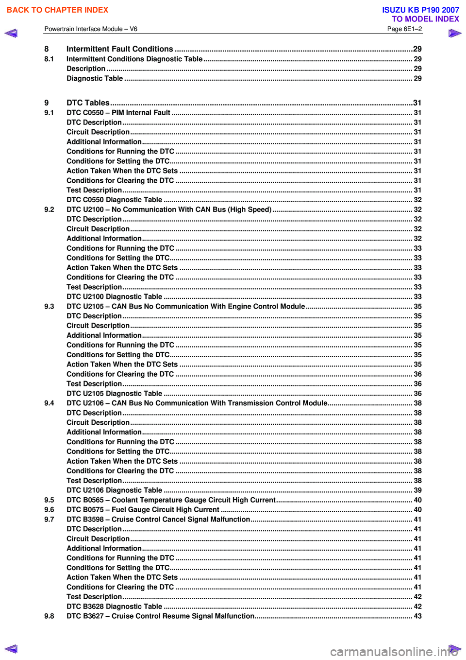
8 Intermittent Fault Conditions ..............................................................................................................29
8.1 Intermittent Conditions Diagnostic Table ....................................................................................... ................... 29
Description ........................................................................................................................................................... 29
Diagnostic Table .................................................................................................................................................. 29
9 DTC Tables ............................................................................................................................................31
9.1 DTC C0550 – PIM Internal Fault ................................................................................................. ......................... 31
DTC Description ................................................................................................................................................... 31
Circuit Description ............................................................................................................................................... 31
Additional Information......................................................................................................... ................................ 31
Conditions for Running the DTC ................................................................................................. ....................... 31
Conditions for Setting the DTC........................................................................................................................... 31
Action Taken When the DTC Sets ................................................................................................. ..................... 31
Conditions for Clearing the DTC ........................................................................................................................ 31
Test Description ................................................................................................................................................... 31
DTC C0550 Diagnostic Table ..................................................................................................... ......................... 32
9.2 DTC U2100 – No Communication With CAN Bus (High Speed) ....................................................................... 32
DTC Description ................................................................................................................................................... 32
Circuit Description ............................................................................................................................................... 32
Additional Information......................................................................................................... ................................ 32
Conditions for Running the DTC ................................................................................................. ....................... 33
Conditions for Setting the DTC........................................................................................................................... 33
Action Taken When the DTC Sets ................................................................................................. ..................... 33
Conditions for Clearing the DTC ........................................................................................................................ 33
Test Description ................................................................................................................................................... 33
DTC U2100 Diagnostic Table ..................................................................................................... ......................... 33
9.3 DTC U2105 – CAN Bus No Communication With Engine Control Module ...................................................... 35
DTC Description ................................................................................................................................................... 35
Circuit Description ............................................................................................................................................... 35
Additional Information......................................................................................................... ................................ 35
Conditions for Running the DTC ................................................................................................. ....................... 35
Conditions for Setting the DTC........................................................................................................................... 35
Action Taken When the DTC Sets ................................................................................................. ..................... 35
Conditions for Clearing the DTC ........................................................................................................................ 36
Test Description ................................................................................................................................................... 36
DTC U2105 Diagnostic Table ..................................................................................................... ......................... 36
9.4 DTC U2106 – CAN Bus No Communication With Transmission Control Module........................................... 38
DTC Description ................................................................................................................................................... 38
Circuit Description ............................................................................................................................................... 38
Additional Information......................................................................................................... ................................ 38
Conditions for Running the DTC ................................................................................................. ....................... 38
Conditions for Setting the DTC........................................................................................................................... 38
Action Taken When the DTC Sets ................................................................................................. ..................... 38
Conditions for Clearing the DTC ........................................................................................................................ 38
Test Description ................................................................................................................................................... 38
DTC U2106 Diagnostic Table ..................................................................................................... ......................... 39
9.5 DTC B0565 – Coolant Temperature Gauge Circuit High Current ..................................................................... 40
9.6 DTC B0575 – Fuel Gauge Circuit High Current ................................................................................................. 40
9.7 DTC B3598 – Cruise Control Cancel Signal Malfunction........................................................................... ....... 41
DTC Description ................................................................................................................................................... 41
Circuit Description ............................................................................................................................................... 41
Additional Information......................................................................................................... ................................ 41
Conditions for Running the DTC ................................................................................................. ....................... 41
Conditions for Setting the DTC........................................................................................................................... 41
Action Taken When the DTC Sets ................................................................................................. ..................... 41
Conditions for Clearing the DTC ........................................................................................................................ 41
Test Description ................................................................................................................................................... 42
DTC B3628 Diagnostic Table ..................................................................................................... ......................... 42
9.8 DTC B3627 – Cruise Control Resume Signal Malfunction........................................................................... ..... 43
BACK TO CHAPTER INDEX
TO MODEL INDEX
ISUZU KB P190 2007
Page 3682 of 6020
Powertrain Interface Module – V6 Page 6E1–21
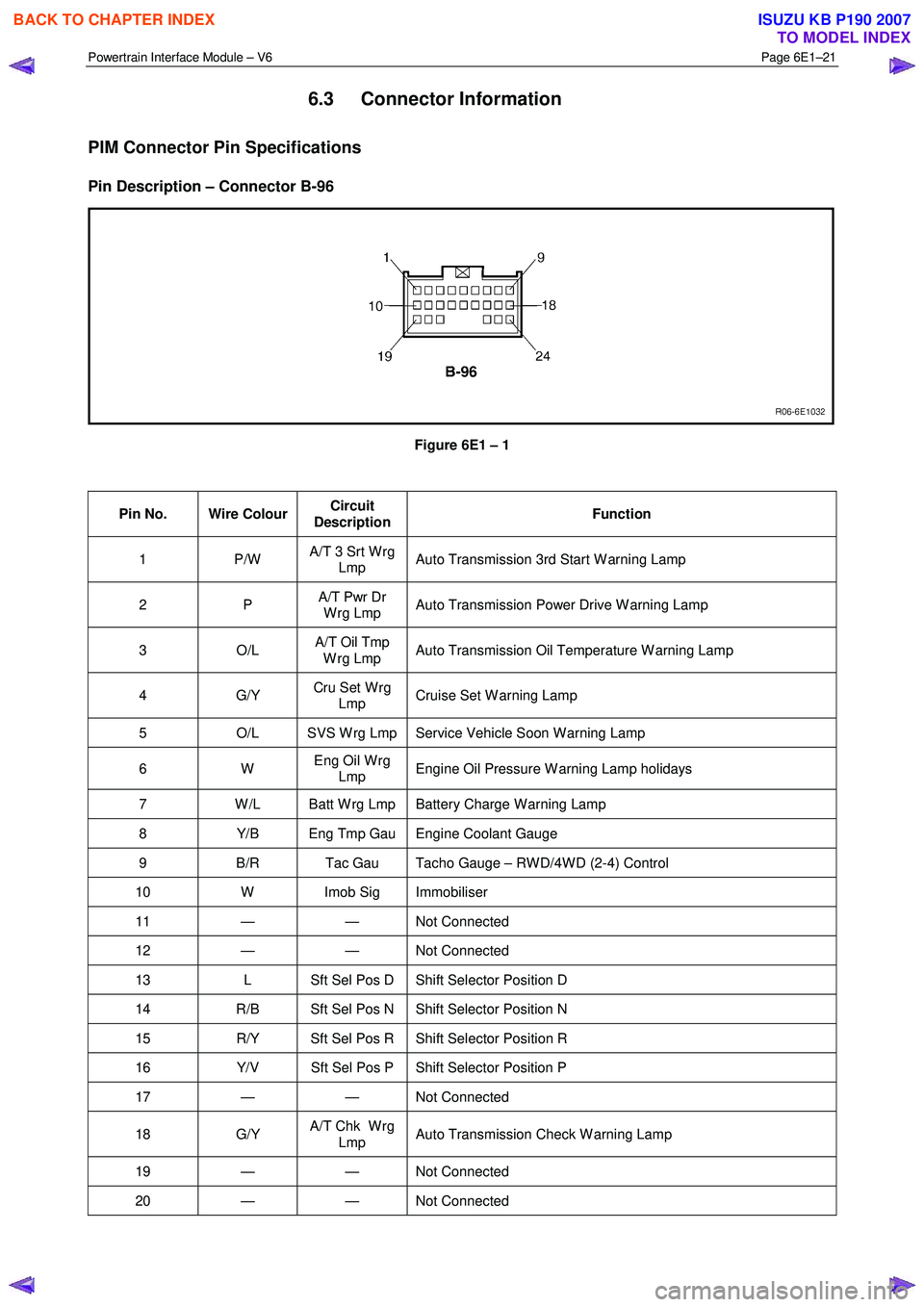
6.3 Connector Information
PIM Connector Pin Specifications
Pin Description – Connector B-96
Figure 6E1 – 1
Pin No. Wire Colour Circuit
Description Function
1 P/W
A/T 3 Srt W rg
Lmp Auto Transmission 3rd Start W arning Lamp
2 P
A/T Pwr Dr
W rg Lmp Auto Transmission Power Drive W arning Lamp
3 O/L A/T Oil Tmp
W rg Lmp Auto Transmission Oil Temperature W arning Lamp
4 G/Y
Cru Set W rg
Lmp Cruise Set W arning Lamp
5
O/L SVS W rg Lmp Service Vehicle Soon W arning Lamp
6 W Eng Oil W rg
Lmp Engine Oil Pressure W arning Lamp holidays
7
W /L Batt W rg Lmp Battery Charge W arning Lamp
8 Y/B Eng Tmp Gau Engine Coolant Gauge
9 B/R Tac Gau Tacho Gauge – RW D/4W D (2-4) Control
10 W Imob Sig Immobiliser
11 — — Not Connected
12 — — Not Connected
13 L Sft Sel Pos D Shift Selector Position D
14 R/B Sft Sel Pos N Shift Selector Position N
15 R/Y Sft Sel Pos R Shift Selector Position R
16 Y/V Sft Sel Pos P Shift Selector Position P
17 — — Not Connected
18 G/Y A/T Chk W rg
Lmp Auto Transmission Check W arning Lamp
19 — — Not
Connected
20 — — Not Connected
BACK TO CHAPTER INDEX
TO MODEL INDEX
ISUZU KB P190 2007
Page 3701 of 6020
Powertrain Interface Module – V6 Page 6E1–40
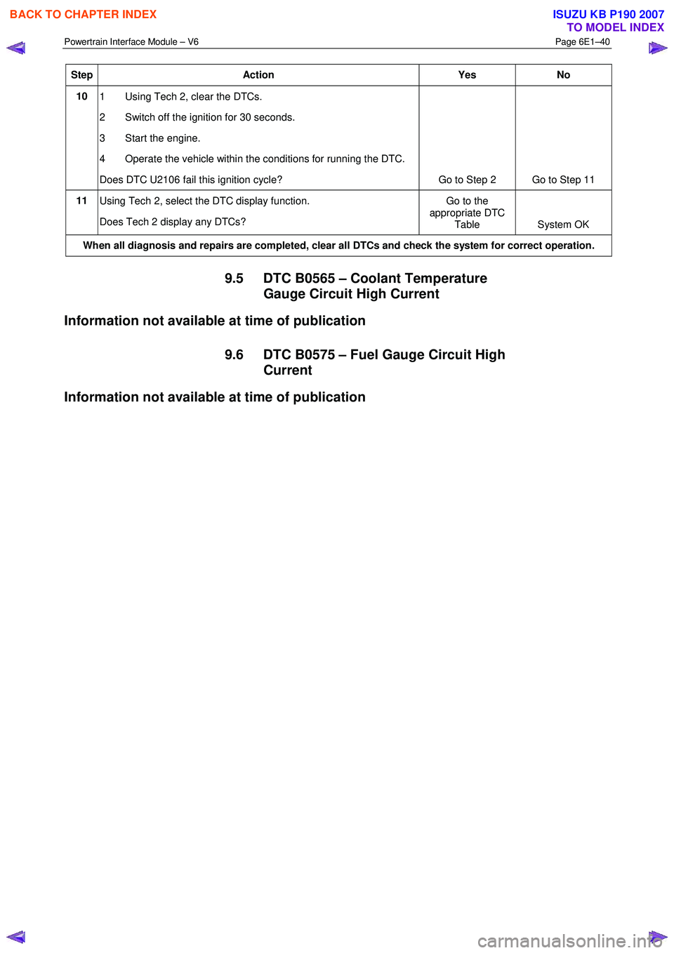
Step Action Yes No
10
1 Using Tech 2, clear the DTCs.
2 Switch off the ignition for 30 seconds.
3 Start the engine.
4 Operate the vehicle within the conditions for running the DTC.
Does DTC U2106 fail this ignition cycle? Go to Step 2 Go to Step 11
11
Using Tech 2, select the DTC display function.
Does Tech 2 display any DTCs? Go to the
appropriate DTC Table System OK
When all diagnosis and repairs are completed, clear all DTCs and check the system for correct operation.
9.5 DTC B0565 – Coolant Temperature
Gauge Circuit High Current
Information not available at time of publication
9.6 DTC B0575 – Fuel Gauge Circuit High Current
Information not available at time of publication
BACK TO CHAPTER INDEX
TO MODEL INDEX
ISUZU KB P190 2007