2007 ISUZU KB P190 engine coolant
[x] Cancel search: engine coolantPage 3520 of 6020
Engine Management – V6 – Diagnostics Page 6C1-2–242
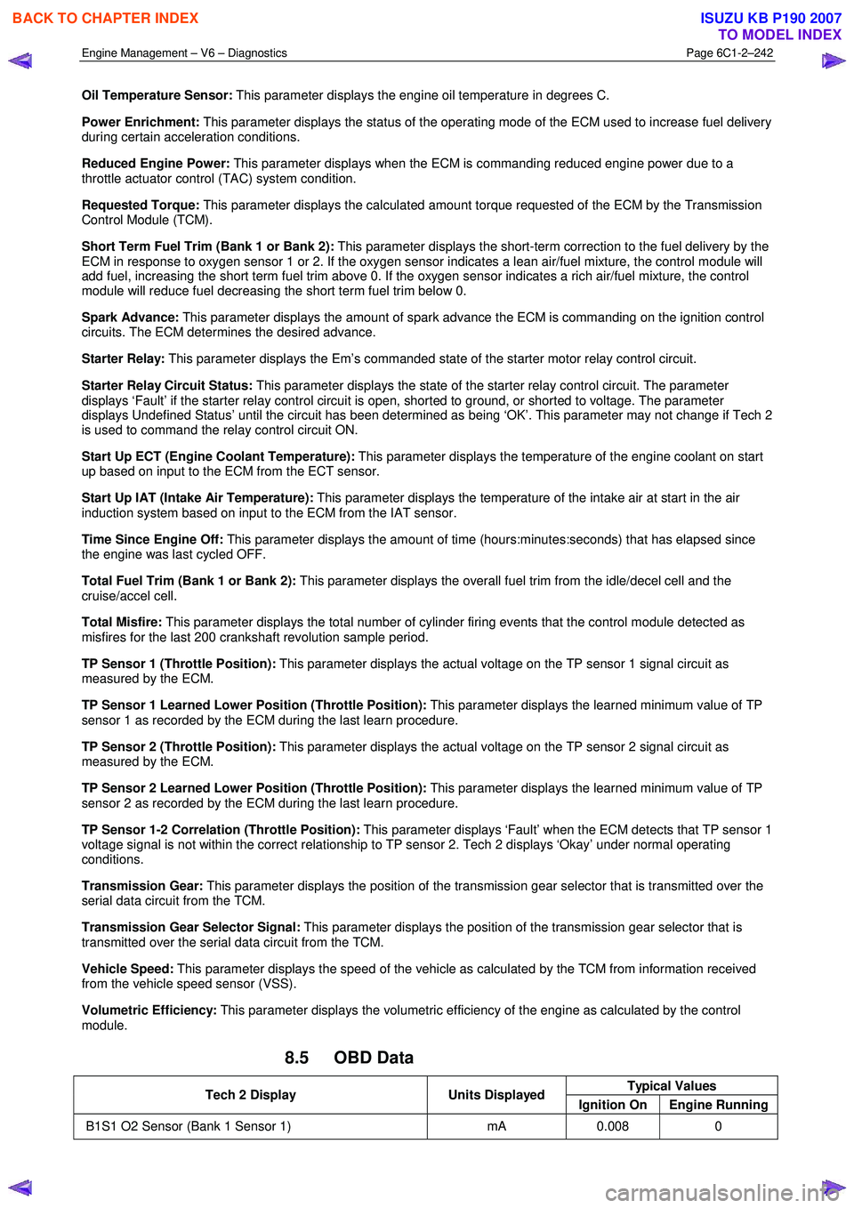
Oil Temperature Sensor: This parameter displays the engine oil temperature in degrees C.
Power Enrichment: This parameter displays the status of the operating mode of the ECM used to increase fuel delivery
during certain acceleration conditions.
Reduced Engine Power: This parameter displays when the ECM is commanding reduced engine power due to a
throttle actuator control (TAC) system condition.
Requested Torque: This parameter displays the calculated amount torque requested of the ECM by the Transmission
Control Module (TCM).
Short Term Fuel Trim (Bank 1 or Bank 2): This parameter displays the short-term correction to the fuel delivery by the
ECM in response to oxygen sensor 1 or 2. If the oxygen sensor indicates a lean air/fuel mixture, the control module will
add fuel, increasing the short term fuel trim above 0. If the oxygen sensor indicates a rich air/fuel mixture, the control
module will reduce fuel decreasing the short term fuel trim below 0.
Spark Advance: This parameter displays the amount of spark advance the ECM is commanding on the ignition control
circuits. The ECM determines the desired advance.
Starter Relay: This parameter displays the Em’s commanded state of the starter motor relay control circuit.
Starter Relay Circuit Status: This parameter displays the state of the starter relay control circuit. The parameter
displays ‘Fault’ if the starter relay control circuit is open, shorted to ground, or shorted to voltage. The parameter
displays Undefined Status’ until the circuit has been determined as being ‘OK’. This parameter may not change if Tech 2
is used to command the relay control circuit ON.
Start Up ECT (Engine Coolant Temperature): This parameter displays the temperature of the engine coolant on start
up based on input to the ECM from the ECT sensor.
Start Up IAT (Intake Air Temperature): This parameter displays the temperature of the intake air at start in the air
induction system based on input to the ECM from the IAT sensor.
Time Since Engine Off: This parameter displays the amount of time (hours:minutes:seconds) that has elapsed since
the engine was last cycled OFF.
Total Fuel Trim (Bank 1 or Bank 2): This parameter displays the overall fuel trim from the idle/decel cell and the
cruise/accel cell.
Total Misfire: This parameter displays the total number of cylinder firing events that the control module detected as
misfires for the last 200 crankshaft revolution sample period.
TP Sensor 1 (Throttle Position): This parameter displays the actual voltage on the TP sensor 1 signal circuit as
measured by the ECM.
TP Sensor 1 Learned Lower Position (Throttle Position): This parameter displays the learned minimum value of TP
sensor 1 as recorded by the ECM during the last learn procedure.
TP Sensor 2 (Throttle Position): This parameter displays the actual voltage on the TP sensor 2 signal circuit as
measured by the ECM.
TP Sensor 2 Learned Lower Position (Throttle Position): This parameter displays the learned minimum value of TP
sensor 2 as recorded by the ECM during the last learn procedure.
TP Sensor 1-2 Correlation (Throttle Position): This parameter displays ‘Fault’ when the ECM detects that TP sensor 1
voltage signal is not within the correct relationship to TP sensor 2. Tech 2 displays ‘Okay’ under normal operating
conditions.
Transmission Gear: This parameter displays the position of the transmission gear selector that is transmitted over the
serial data circuit from the TCM.
Transmission Gear Selector Signal: This parameter displays the position of the transmission gear selector that is
transmitted over the serial data circuit from the TCM.
Vehicle Speed: This parameter displays the speed of the vehicle as calculated by the TCM from information received
from the vehicle speed sensor (VSS).
Volumetric Efficiency: This parameter displays the volumetric efficiency of the engine as calculated by the control
module.
8.5 OBD Data
Typical Values Tech 2 Display Units Displayed
Ignition On Engine Running
B1S1 O2 Sensor (Bank 1 Sensor 1) mA 0.008 0
BACK TO CHAPTER INDEX
TO MODEL INDEX
ISUZU KB P190 2007
Page 3521 of 6020
Engine Management – V6 – Diagnostics Page 6C1-2–243
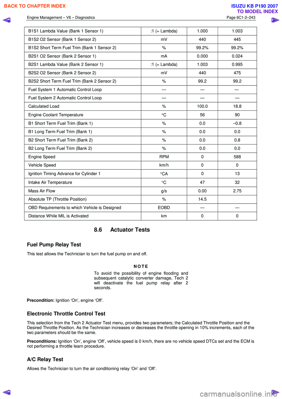
B1S1 Lambda Value (Bank 1 Sensor 1) :1 (= Lambda) 1.000 1.003
B1S2 O2 Sensor (Bank 1 Sensor 2) mV 440 445
B1S2 Short Term Fuel Trim (Bank 1 Sensor 2) % 99.2% 99.2%
B2S1 O2 Sensor (Bank 2 Sensor 1) mA 0.000 0.024
B2S1 Lambda Value (Bank 2 Sensor 1) :1 (= Lambda) 1.003 0.995
B2S2 O2 Sensor (Bank 2 Sensor 2) mV 440 475
B2S2 Short Term Fuel Trim (Bank 2 Sensor 2) % 99.2 99.2
Fuel System 1 Automatic Control Loop — — —
Fuel System 2 Automatic Control Loop — — —
Calculated Load % 100.0 18.8
Engine Coolant Temperature
°C 56 90
B1 Short Term Fuel Trim (Bank 1)
% 0.0 –0.8
B1 Long Term Fuel Trim (Bank 1) % 0.0 0.0
B2 Short Term Fuel Trim (Bank 2) % 0.0 0.8
B2 Long Term Fuel Trim (Bank 2) % 0.0 0.0
Engine Speed RPM 0 588
Vehicle Speed km/h 0 0
Ignition Timing Advance for Cylinder 1
°CA 0 13
Intake Air Temperature
°C 47 32
Mass Air Flow
g/s 0.00 2.75
Absolute TP (Throttle Position) % 14.5
OBD Requirements to which Vehicle is Designed EOBD — —
Distance W hile MIL is Activated km 0 0
8.6 Actuator Tests
Fuel Pump Relay Test
This test allows the Technician to turn the fuel pump on and off.
NOTE
To avoid the possibility of engine flooding and
subsequent catalytic converter damage, Tech 2
will deactivate the fuel pump relay after 2
seconds.
Precondition: Ignition ‘On’, engine ‘Off’.
Electronic Throttle Control Test
This selection from the Tech 2 Actuator Test menu, provides two parameters; the Calculated Throttle Position and the
Desired Throttle Position. As the Technician increases or decreases the throttle opening in 10% increments, each of the
two parameters should be the same.
Preconditions: Ignition ‘On’, engine ‘Off’, vehicle speed is 0 km/h, there are no vehicle speed DTCs set and the ECM is
not performing a throttle learn procedure.
A/C Relay Test
Allows the Technician to turn the air conditioning relay ‘On’ and ‘Off’.
BACK TO CHAPTER INDEX
TO MODEL INDEX
ISUZU KB P190 2007
Page 3522 of 6020
Engine Management – V6 – Diagnostics Page 6C1-2–244
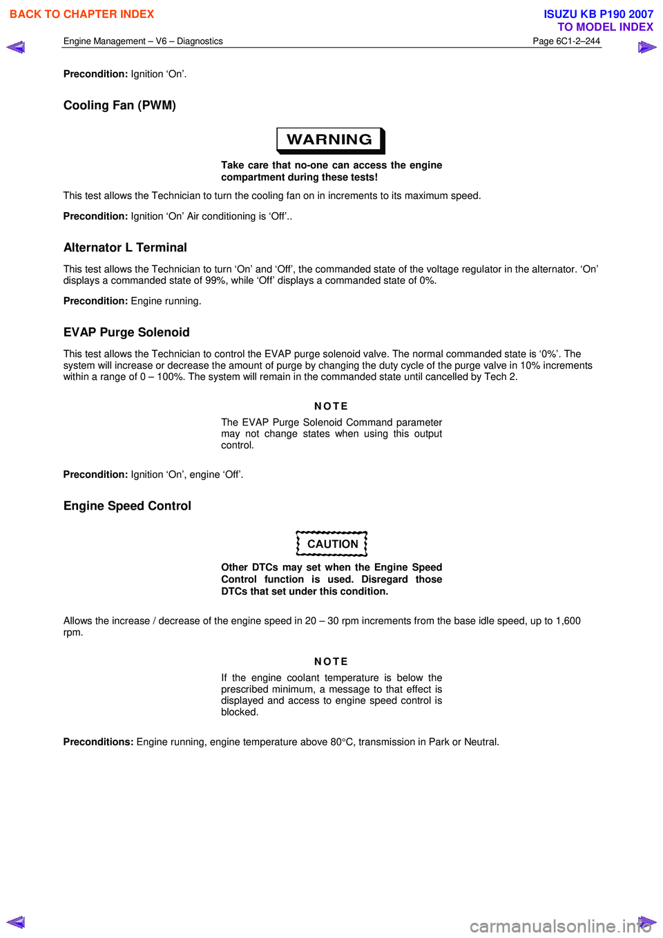
Precondition: Ignition ‘On’.
Cooling Fan (PWM)
Take care that no-one can access the engine
compartment during these tests!
This test allows the Technician to turn the cooling fan on in increments to its maximum speed.
Precondition: Ignition ‘On’ Air conditioning is ‘Off’..
Alternator L Terminal
This test allows the Technician to turn ‘On’ and ‘Off’, the commanded state of the voltage regulator in the alternator. ‘On’
displays a commanded state of 99%, while ‘Off’ displays a commanded state of 0%.
Precondition: Engine running.
EVAP Purge Solenoid
This test allows the Technician to control the EVAP purge solenoid valve. The normal commanded state is ‘0%’. The
system will increase or decrease the amount of purge by changing the duty cycle of the purge valve in 10% increments
within a range of 0 – 100%. The system will remain in the commanded state until cancelled by Tech 2.
NOTE
The EVAP Purge Solenoid Command parameter
may not change states when using this output
control.
Precondition: Ignition ‘On’, engine ‘Off’.
Engine Speed Control
Other DTCs may set when the Engine Speed
Control function is used. Disregard those
DTCs that set under this condition.
Allows the increase / decrease of the engine speed in 20 – 30 rpm increments from the base idle speed, up to 1,600
rpm.
NOTE
If the engine coolant temperature is below the
prescribed minimum, a message to that effect is
displayed and access to engine speed control is
blocked.
Preconditions: Engine running, engine temperature above 80 °C, transmission in Park or Neutral.
BACK TO CHAPTER INDEX
TO MODEL INDEX
ISUZU KB P190 2007
Page 3525 of 6020
Engine Management – V6 – Service Operations Page 6C1-3–1
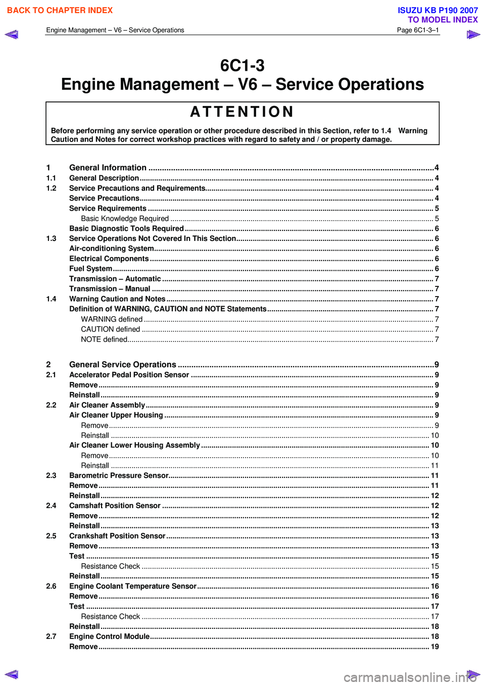
6C1-3
Engine Management – V6 – Service Operations
ATTENTION
Before performing any service operation or other procedure described in this Section, refer to 1.4 Warning
Caution and Notes for correct workshop practices with regard to safety and / or property damage.
1 General Information ............................................................................................................ ...................4
1.1 General Description ............................................................................................................ ................................... 4
1.2 Service Precautions and Requirements........................................................................................... .................... 4
Service Precautions............................................................................................................................................... 4
Service Requirements ........................................................................................................................................... 5
Basic Knowledge Required ....................................................................................................... ......................... 5
Basic Diagnostic Tools Required ......................................................................................................................... 6
1.3 Service Operations Not Covered In This Section................................................................................. ............... 6
Air-conditioning System........................................................................................................................................ 6
Electrical Components .......................................................................................................................................... 6
Fuel System ............................................................................................................................................................ 6
Transmission – Automatic ....................................................................................................... ............................. 7
Transmission – Manual ......................................................................................................................................... 7
1.4 Warning Caution and Notes .................................................................................................................................. 7
Definition of WARNING, CAUTION and NOTE Statements ............................................................................. .... 7
WARNING defined ............................................................................................................................................. 7
CAUTION defined .............................................................................................................................................. 7
NOTE defined..................................................................................................................................................... 7
2 General Service Operations ..................................................................................................... .............9
2.1 Accelerator Pedal Position Sensor .............................................................................................. ........................ 9
Remove ................................................................................................................................................................... 9
Reinstall .................................................................................................................................................................. 9
2.2 Air Cleaner Assembly ............................................................................................................................................ 9
Air Cleaner Upper Housing ...................................................................................................... ............................. 9
Remove .............................................................................................................................................................. 9
Reinstall ........................................................................................................................................................... 10
Air Cleaner Lower Housing Assembly ............................................................................................. .................. 10
Remove ............................................................................................................................................................ 10
Reinstall ........................................................................................................................................................... 11
2.3 Barometric Pressure Sensor..................................................................................................... .......................... 11
Remove ................................................................................................................................................................. 11
Reinstall ................................................................................................................................................................ 12
2.4 Camshaft Position Sensor ....................................................................................................... ........................... 12
Remove ................................................................................................................................................................. 12
Reinstall ................................................................................................................................................................ 13
2.5 Crankshaft Position Sensor ..................................................................................................... ........................... 13
Remove ................................................................................................................................................................. 13
Test ....................................................................................................................................................................... 15
Resistance Check ............................................................................................................... ............................. 15
Reinstall ................................................................................................................................................................ 15
2.6 Engine Coolant Temperature Sensor .............................................................................................. ................... 16
Remove ................................................................................................................................................................. 16
Test ....................................................................................................................................................................... 17
Resistance Check ............................................................................................................... ............................. 17
Reinstall ................................................................................................................................................................ 18
2.7 Engine Control Module.......................................................................................................... .............................. 18
Remove ................................................................................................................................................................. 19
BACK TO CHAPTER INDEX
TO MODEL INDEX
ISUZU KB P190 2007
Page 3531 of 6020
Engine Management – V6 – Service Operations Page 6C1-3–7
Transmission – Automatic
For automatic transmission sensors and components, refer to 7C4 Automatic Transmission – 4L60E – On-vehicle
Servicing.
Transmission – Manual
For manual transmission sensors and other components, refer to 7B1 Manual Transmission – V6.
1.4 Warning Caution and Notes
This Section contains various W ARNINGS, CAUTIONS and NOTE statements that you must observe carefully to reduce
the risk of death or injury during service, repair procedures or vehicle operation. Incorrect service or repair procedures
may damage the vehicle or cause operational faults. W ARNINGS, CAUTION and NOTE statements are not exhaustive.
GM Holden LTD can not possibly warn of all the potentially hazardous consequences of failure to follow these
instructions.
Definition of WARNING, CAUTION and NOTE Statements
Diagnosis and repair procedures in this Section contain both general and specific W ARNING, CAUTION and NOTE
statements. GM Holden LTD is dedicated to the presentation of service information that helps the technician to diagnose
and repair the systems necessary for proper operation of the vehicle. Certain procedures may present a hazard to the
technician if they are not followed in the recommended manner. W ARNING, CAUTION and NOTE statements are
designed to help prevent these hazards from occurring, but not all hazards can be foreseen.
WARNING defined
A W ARNING statement immediately precedes an operating procedure or maintenance practice which, if not correctly
followed, could result in death or injury. A W ARNING statement alerts you to take necessary action or not to take a
prohibited action. If a W ARNING statement is ignored, the following consequences may occur:
• Death or injury to the technician or other personnel working on the vehicle,
• Death or injury to other people in or near the workplace area, and / or
• Death or injury to the driver / or passenger(s) of the vehicle or other people, if the vehicle has been improperly
repaired.
CAUTION defined
A CAUTION statement immediately precedes an operating procedure or maintenance practice which, if not correctly
followed, could result in damage to or destruction of equipment, or corruption of data. If a CAUTION statement is ignored,
the following consequences may occur:
• Damage to the vehicle,
• Unnecessary vehicle repairs or component replacement,
• Faulty operation or performance of any system or component being repaired,
• Damage to any system or components which depend on the proper operation of the system or component being
repaired,
• Faulty operation or performance of any systems or components which depend on the proper operation or
performance of the system or component under repair,
• Damage to fasteners, basic tools or special tools and / or
• Leakage of coolant, lubricant or other vital fluids.
NOTE defined
A NOTE statement immediately precedes or follows an operating procedure, maintenance practice or condition that
requires highlighting. A NOTE statement also emphasises necessary characteristics of a diagnostic or repair procedure.
A NOTE statement is designed to:
• Clarify a procedure,
• Present additional information for accomplishing a procedure,
BACK TO CHAPTER INDEX
TO MODEL INDEX
ISUZU KB P190 2007
Page 3540 of 6020
Engine Management – V6 – Service Operations Page 6C1-3–16
2.6 Engine Coolant Temperature Sensor
Remove
To avoid serious personal injury, never
remove the engine coolant temperature (ECT)
sensor when the engine is hot. Allow the
engine to cool to ambient temperature (less
than 50 °
°°
°
C) before performing this procedure.
1 Turn the ignition switch off.
To avoid serious personal injury, never
remove the coolant filler cap when the engine
is hot. Allow the engine to cool to ambient
temperature (less than 50 °
°°
°
C) before
performing this procedure.
2 Allow the engine to cool to ambient temperature less than 50 °C, and slowly remove coolant filler cap located on the
coolant outlet housing.
3 Drain approximately two litres of coolant into a suitable container, refer to 6B1 – Engine Cooling – V6.
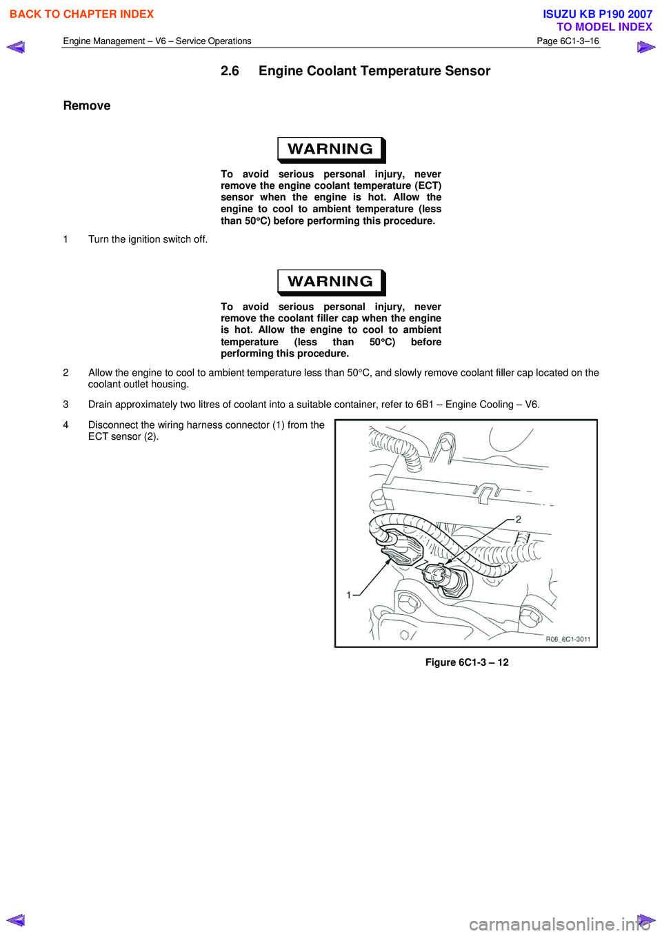
4 Disconnect the wiring harness connector (1) from the ECT sensor (2).
Figure 6C1-3 – 12
BACK TO CHAPTER INDEX
TO MODEL INDEX
ISUZU KB P190 2007
Page 3541 of 6020
Engine Management – V6 – Service Operations Page 6C1-3–17
Clean the area around the ECT before
removal to avoid debris from entering the
engine.
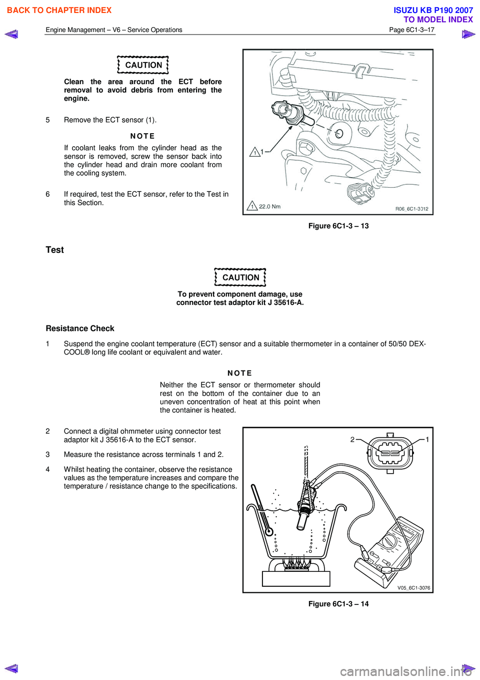
5 Remove the ECT sensor (1). NOTE
If coolant leaks from the cylinder head as the
sensor is removed, screw the sensor back into
the cylinder head and drain more coolant from
the cooling system.
6 If required, test the ECT sensor, refer to the Test in this Section.
Figure 6C1-3 – 13
Test
To prevent component damage, use
connector test adaptor kit J 35616-A.
Resistance Check
1 Suspend the engine coolant temperature (ECT) sensor and a suitable thermometer in a container of 50/50 DEX- COOL® long life coolant or equivalent and water.
NOTE
Neither the ECT sensor or thermometer should
rest on the bottom of the container due to an
uneven concentration of heat at this point when
the container is heated.
2 Connect a digital ohmmeter using connector test adaptor kit J 35616-A to the ECT sensor.
3 Measure the resistance across terminals 1 and 2.
4 W hilst heating the container, observe the resistance values as the temperature increases and compare the
temperature / resistance change to the specifications.
Figure 6C1-3 – 14
BACK TO CHAPTER INDEX
TO MODEL INDEX
ISUZU KB P190 2007
Page 3542 of 6020
Engine Management – V6 – Service Operations Page 6C1-3–18
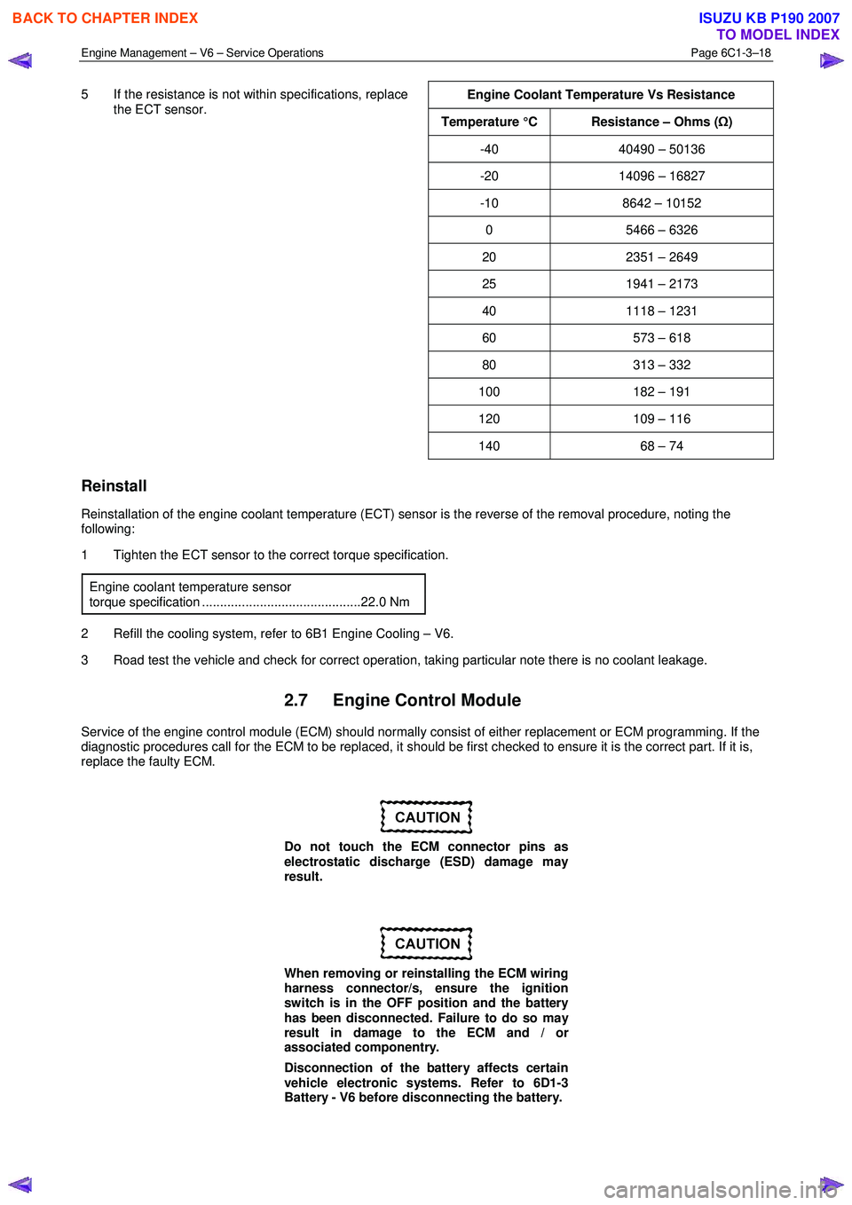
5 If the resistance is not within specifications, replace
the ECT sensor.
Engine Coolant Temperature Vs Resistance
Temperature °C Resistance – Ohms (
Ω)
-40 40490 – 50136
-20 14096 – 16827
-10 8642 – 10152
0 5466 – 6326
20 2351 – 2649
25 1941 – 2173
40 1118 – 1231
60 573 – 618
80 313 – 332
100 182 – 191
120 109 – 116
140 68 – 74
Reinstall
Reinstallation of the engine coolant temperature (ECT) sensor is the reverse of the removal procedure, noting the
following:
1 Tighten the ECT sensor to the correct torque specification.
Engine coolant temperature sensor
torque specification ............................................22.0 Nm
2 Refill the cooling system, refer to 6B1 Engine Cooling – V6.
3 Road test the vehicle and check for correct operation, taking particular note there is no coolant leakage.
2.7 Engine Control Module
Service of the engine control module (ECM) should normally consist of either replacement or ECM programming. If the
diagnostic procedures call for the ECM to be replaced, it should be first checked to ensure it is the correct part. If it is,
replace the faulty ECM.
Do not touch the ECM connector pins as
electrostatic discharge (ESD) damage may
result.
When removing or reinstalling the ECM wiring
harness connector/s, ensure the ignition
switch is in the OFF position and the battery
has been disconnected. Failure to do so may
result in damage to the ECM and / or
associated componentry.
Disconnection of the battery affects certain
vehicle electronic systems. Refer to 6D1-3
Battery - V6 before disconnecting the battery.
BACK TO CHAPTER INDEX
TO MODEL INDEX
ISUZU KB P190 2007