Page 2658 of 6020
Engine Mechanical – V6 Page 6A1–179
1 Ensure all fasteners are tightened to the correct torque specification.
2 Using crankshaft rotation Tool No. EN-46111 (1), align the crankshaft sprocket timing mark (2) with the
indexing mark (3) on the oil pump housing.
Figure 6A1 – 310
3 Ensure the deck face is clean and the cylinder head locating pins are securely mounted in the cylinder
block deck face.
4 Install a new cylinder head gasket (1) using the deck face locating pins for retention.
Figure 6A1 – 311
5 Align the cylinder head with the locating pins.
6 Place the cylinder head in position on the deck face.
NOTE
Do not allow oil on the cylinder head bolt
bosses.
CAUTION
Do not reuse the old M11 cylinder head bolts
(1 to 8 inclusive).
7 Install new M11 cylinder head bolt (1), eight places, and tighten in the sequence shown and to the correct
torque specification.
Figure 6A1 – 312
BACK TO CHAPTER INDEX
TO MODEL INDEX
ISUZU KB P190 2007
Page 2662 of 6020

Engine Mechanical – V6 Page 6A1–183
• The hard rubber surface is covered with heat check cracks,
• The rubber is split through the centre of the engine mount, or
• The rubber is separated from the metal plate portion of the engine mount.
5 Remove the engine lift brackets, Tool No. EN-46114 from the engine.
Reinstall
The reinstallation procedure for the engine mounts is the reverse of the removal procedure, noting the following:
Ensure all fasteners are tightened to the correct torque specification.
Engine mount bracket to
cylinder block attaching bolt
torque specification
................................................................43.0 – 57.0 Nm
Engine mount to bracket attaching nut
torque specification
................................................................70.0 – 90.0 Nm
Engine mount to frame attaching nut
torque specification
................................................................44.0 – 60.0 Nm
BACK TO CHAPTER INDEX
TO MODEL INDEX
ISUZU KB P190 2007
Page 2663 of 6020

Engine Mechanical – V6 Page 6A1–184
4 Major Service Operations
ATTENTION
The V6 engine is a combination of numerous components, containing machined, honed, polished and lapped
surfaces manufactured on the latest, high technology production equipment. Many of the components
contain tolerances measured in thousandths of a millimetre. Consequently, when any engine component is to
be serviced, care and cleanliness are extremely important.
Prior to re-assembly of the V6 engine, all components must be cleaned and inspected in accordance with the
relevant procedures throughout this section, and replaced or repaired where required.
In addition to cleaning and inspecting components, a liberal coating of engine oil should be applied to friction
surfaces during assembly to protect and lubricate the surfaces on initial operation.
When performing any service operation contained in this Section, it should be understood that correct
cleaning and protection of machined surfaces and friction areas is part of the repair procedure. This is
considered standard workshop practice, even if not specifically stated. Torque values must be used as
specified during reassembly to ensure correct retention of all components.
Through out this section, fastener torque wrench specifications may be accompanied with the following
identification marks:
■ Fasteners must be replaced after loosening.
Fasteners either have micro encapsulated sealant applied or incorporate a mechanical thread lock and
should only be re-used once. If in doubt, replacement is recommended.
If one of these identification marks is present alongside a fastener torque wrench specification, the
recommendation regarding that fastener must be adhered to.
4.1 Engine Removal
CAUTION
• Allow the engine to cool to at least 50 °
°°
°
C,
before attempting fastener removal.
• As aluminium has a greater rate of thermal
expansion than that of cast iron,
aluminium bolt hole threads will change
dimension to a larger extent than cast iron
bolt threads.
• If a bolt or other threaded component is
removed before the engine is allowed to
cool to at least 50 °
°°
°
C, threads could be
pulled from the cylinder block or cylinder
head.
• Do not use impact tools to remove bolts
during engine disassembly. While this may
be common practice with cast iron engine
components, use of these tools is likely to
pull the aluminium threads in the cylinder
block or head of this engine.
BACK TO CHAPTER INDEX
TO MODEL INDEX
ISUZU KB P190 2007
Page 2666 of 6020

Engine Mechanical – V6 Page 6A1–187
Plug the fuel feed hose after removal to
prevent dirt entering the pipe.
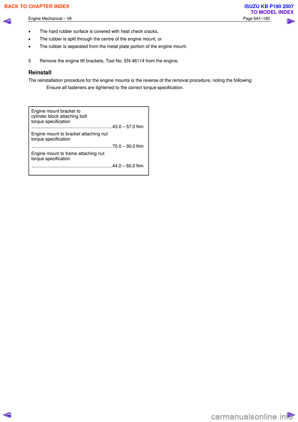
12 Disconnect the fuel pipe connector and injector harness connector.
13 Disconnect the fuel feed hose from the fuel rail (1), refer to 6C Fuel system.
14 Pull out release bar (2) of the fuel injector harness wiring connector (3).
15 Disconnect the fuel injector harness wiring connector from the fuel injector wiring harness (4).
Figure 6A1 – 321
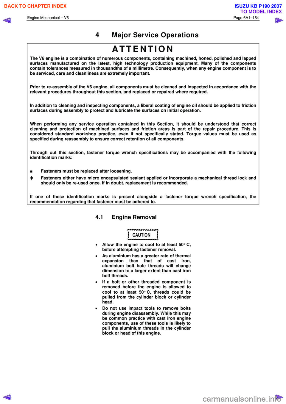
16 To disconnect the throttle body connector (1) the following procedure must be followed.
17 Retract the throttle body wiring connector lock (3) while pressing the connector latch in the direction of
the arrow (4).
18 Disconnect the throttle body wiring connector (1).
19 Release the throttle body connector wiring harness from its retaining clip (5).
Take care not to break the barbed retainer
pin (6), when removing the harness. Should
the pin be damaged it is vital that a new
harness retainer be fitted.
20 Remove the main wiring harness retainer pin (6) from the intake manifold by pushing from the front to the
rear using a suitable length of 5mm steel rod or an
allen key.
Figure 6A1 – 322
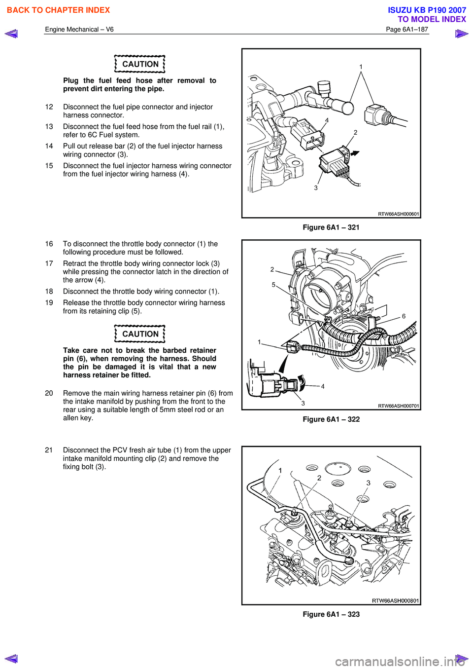
21 Disconnect the PCV fresh air tube (1) from the upper intake manifold mounting clip (2) and remove the
fixing bolt (3).
Figure 6A1 – 323
BACK TO CHAPTER INDEX
TO MODEL INDEX
ISUZU KB P190 2007
Page 2671 of 6020
Engine Mechanical – V6 Page 6A1–192
44 Remove the left-hand side engine mount (1), (automatic transmission only).
Figure 6A1 – 336
45 Unclip the oil level sensor harness from the heat shield (1).
a Remove the heat shield retaining screw (2).
b Remove the lower starter motor attaching bolt (3).
c Remove the heat shield.
d Remove the upper starter motor retaining bolt (3).
46 Remove the starter motor from the engine block and lower the starter motor as far as possible to gain
access to the wiring harness connections.
47 Remove the starter motor, (automatic transmission only).
Figure 6A1 – 337
48 Reinstall the left-hand side engine mount (1), (automatic transmission only).
49 Remove the transmission assembly, refer to 7C1 Automatic – 4L60E – General Information.
BACK TO CHAPTER INDEX
TO MODEL INDEX
ISUZU KB P190 2007
Page 2672 of 6020
Engine Mechanical – V6 Page 6A1–193
Figure 6A1 – 338
50 Unplug the connector from the oil level sensor (1).
51 Remove the attaching bolt (2) holding the ground cable to the engine block.
Figure 6A1 – 339
52 Remove the accessory drive belt using a socket wrench (1), to reduce tension rotate the drive belt
tensioner (2) clockwise, then while holding the
tensioner in the reduced tension position, remove the
accessory drive belt (3).
Figure 6A1 – 340
53 Remove the power steering pump bolts (two places), remove the pump (1) from the mounting bracket and
disconnect the power steering hoses (two places)
from the pump body.
NOTE
Plug the open ends of the power steering hoses
to prevent the ingress of contaminants.
Figure 6A1 – 341
BACK TO CHAPTER INDEX
TO MODEL INDEX
ISUZU KB P190 2007
Page 2678 of 6020
Engine Mechanical – V6 Page 6A1–199
5 Remove the two long bolts (1) attaching the rear of
the oil pan to the crankshaft rear oil seal housing.
6 Remove the remaining eleven bolts attaching the oil pan to the cylinder block.
7 Using the shear points located at the edge of the oil pan shear the RTV sealant.
8 Remove the oil pan from the cylinder block.
Figure 6A1 – 353
BACK TO CHAPTER INDEX
TO MODEL INDEX
ISUZU KB P190 2007
Page 2680 of 6020

Engine Mechanical – V6 Page 6A1–201
Inspect
1 Inspect the exterior of the oil pan for the following
conditions:
• Damage to the drain plug or drain plug hole,
• Damage to the transmission mounting bosses,
• Damage to the oil level sensor threads, and
• Dents or damage to the exterior.
2 Inspect the interior of the oil pan for the following conditions:
• Gouges or damage to the oil pan sealing
surfaces,
• Damage to the crankshaft oil deflector,
• Damage to the bolt holes,
• Damage to the oil suction tube mounting
bosses, and
• Damage to the crankshaft oil deflector mounting
bosses.
Figure 6A1 – 355
3 Inspect the oil pan deflector for damage.
4 Repair or replace the oil pan deflector and/or oil pan as required.
Figure 6A1 – 356
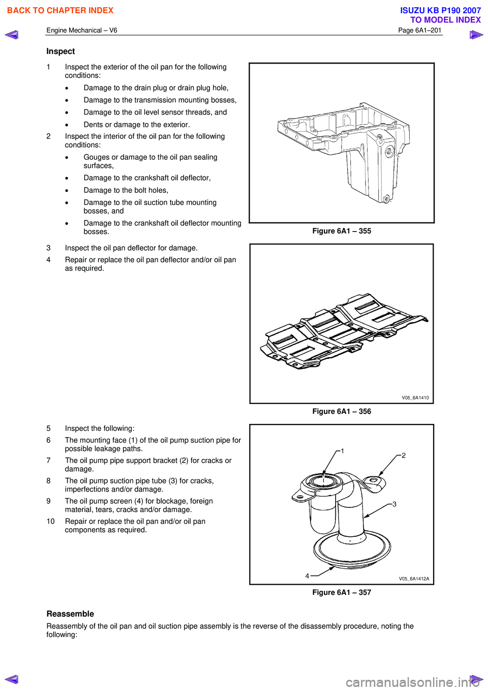
5 Inspect the following:
6 The mounting face (1) of the oil pump suction pipe for possible leakage paths.
7 The oil pump pipe support bracket (2) for cracks or damage.
8 The oil pump suction pipe tube (3) for cracks, imperfections and/or damage.
9 The oil pump screen (4) for blockage, foreign material, tears, cracks and/or damage.
10 Repair or replace the oil pan and/or oil pan components as required.
Figure 6A1 – 357
Reassemble
Reassembly of the oil pan and oil suction pipe assembly is the reverse of the disassembly procedure, noting the
following:
BACK TO CHAPTER INDEX
TO MODEL INDEX
ISUZU KB P190 2007