2007 ISUZU KB P190 turbo
[x] Cancel search: turboPage 1090 of 6020
6E-56 Engine Control System (4JH1)
DTC
(Symptom Code) Flash
Code MIL
Status DTC Name on
scan tool Condition for
Running the DTC Condition for
Setting the DTC Possible Cause
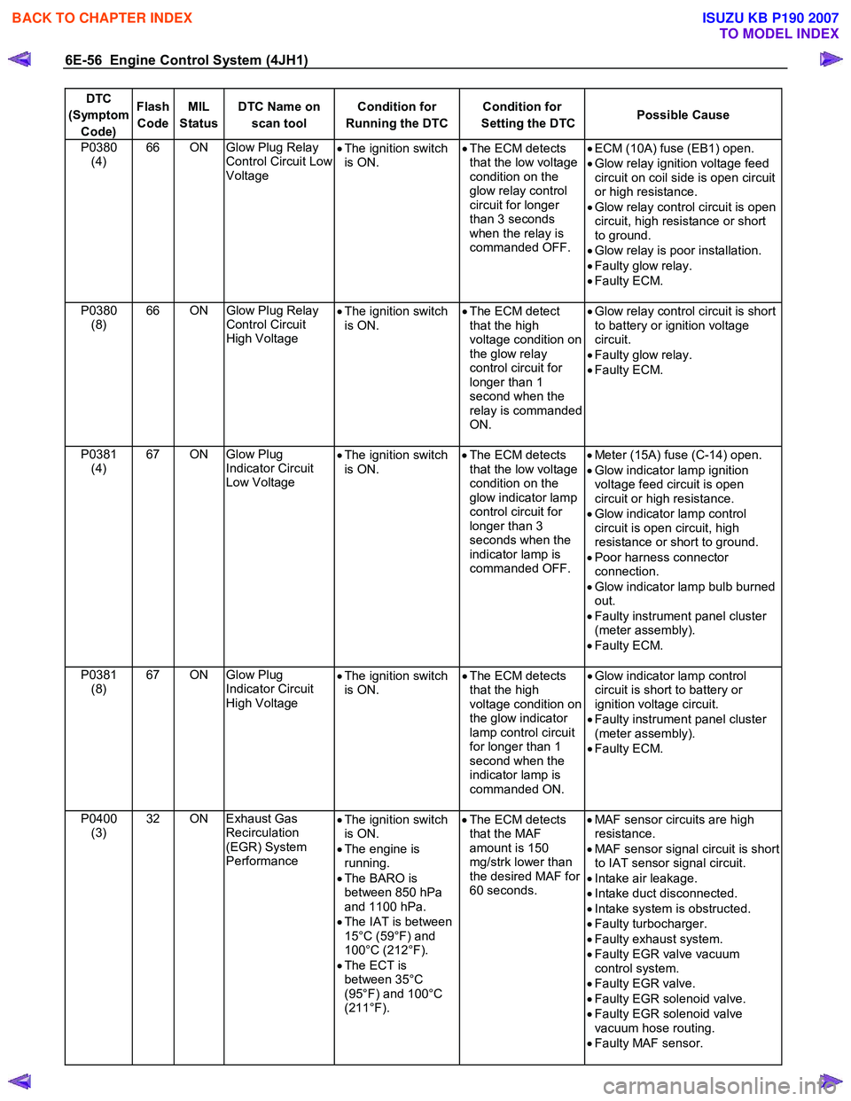
P0380
(4) 66 ON Glow Plug Relay
Control Circuit Low
Voltage •
The ignition switch
is ON. •
The ECM detects
that the low voltage
condition on the
glow relay control
circuit for longer
than 3 seconds
when the relay is
commanded OFF.
•
ECM (10A) fuse (EB1) open.
• Glow relay ignition voltage feed
circuit on coil side is open circuit
or high resistance.
• Glow relay control circuit is open
circuit, high resistance or short
to ground.
• Glow relay is poor installation.
• Faulty glow relay.
• Faulty ECM.
P0380 (8) 66 ON
Glow Plug Relay
Control Circuit
High Voltage •
The ignition switch
is ON. •
The ECM detect
that the high
voltage condition on
the glow relay
control circuit for
longer than 1
second when the
relay is commanded
ON.
•
Glow relay control circuit is short
to battery or ignition voltage
circuit.
• Faulty glow relay.
• Faulty ECM.
P0381 (4) 67 ON Glow Plug
Indicator Circuit
Low Voltage •
The ignition switch
is ON.
•
The ECM detects
that the low voltage
condition on the
glow indicator lamp
control circuit for
longer than 3
seconds when the
indicator lamp is
commanded OFF.
•
Meter (15A) fuse (C-14) open.
• Glow indicator lamp ignition
voltage feed circuit is open
circuit or high resistance.
• Glow indicator lamp control
circuit is open circuit, high
resistance or short to ground.
• Poor harness connector
connection.
• Glow indicator lamp bulb burned
out.
• Faulty instrument panel cluster
(meter assembly).
• Faulty ECM.
P0381 (8) 67 ON Glow Plug
Indicator Circuit
High Voltage •
The ignition switch
is ON. •
The ECM detects
that the high
voltage condition on
the glow indicator
lamp control circuit
for longer than 1
second when the
indicator lamp is
commanded ON.
•
Glow indicator lamp control
circuit is short to battery or
ignition voltage circuit.
• Faulty instrument panel cluster
(meter assembly).
• Faulty ECM.
P0400 (3) 32 ON Exhaust Gas
Recirculation
(EGR) System
Performance •
The ignition switch
is ON.
• The engine is
running.
• The BARO is
between 850 hPa
and 1100 hPa.
• The IAT is between
15°C (59°F) and
100°C (212°F).
• The ECT is
between 35°C
(95°F) and 100°C
(211°F).
•
The ECM detects
that the MAF
amount is 150
mg/strk lower than
the desired MAF for
60 seconds.
•
MAF sensor circuits are high
resistance.
• MAF sensor signal circuit is short
to IAT sensor signal circuit.
• Intake air leakage.
• Intake duct disconnected.
• Intake system is obstructed.
• Faulty turbocharger.
• Faulty exhaust system.
• Faulty EGR valve vacuum
control system.
• Faulty EGR valve.
• Faulty EGR solenoid valve.
• Faulty EGR solenoid valve
vacuum hose routing.
• Faulty MAF sensor.
BACK TO CHAPTER INDEX
TO MODEL INDEX
ISUZU KB P190 2007
Page 1100 of 6020
6E-66 Engine Control System (4JH1)
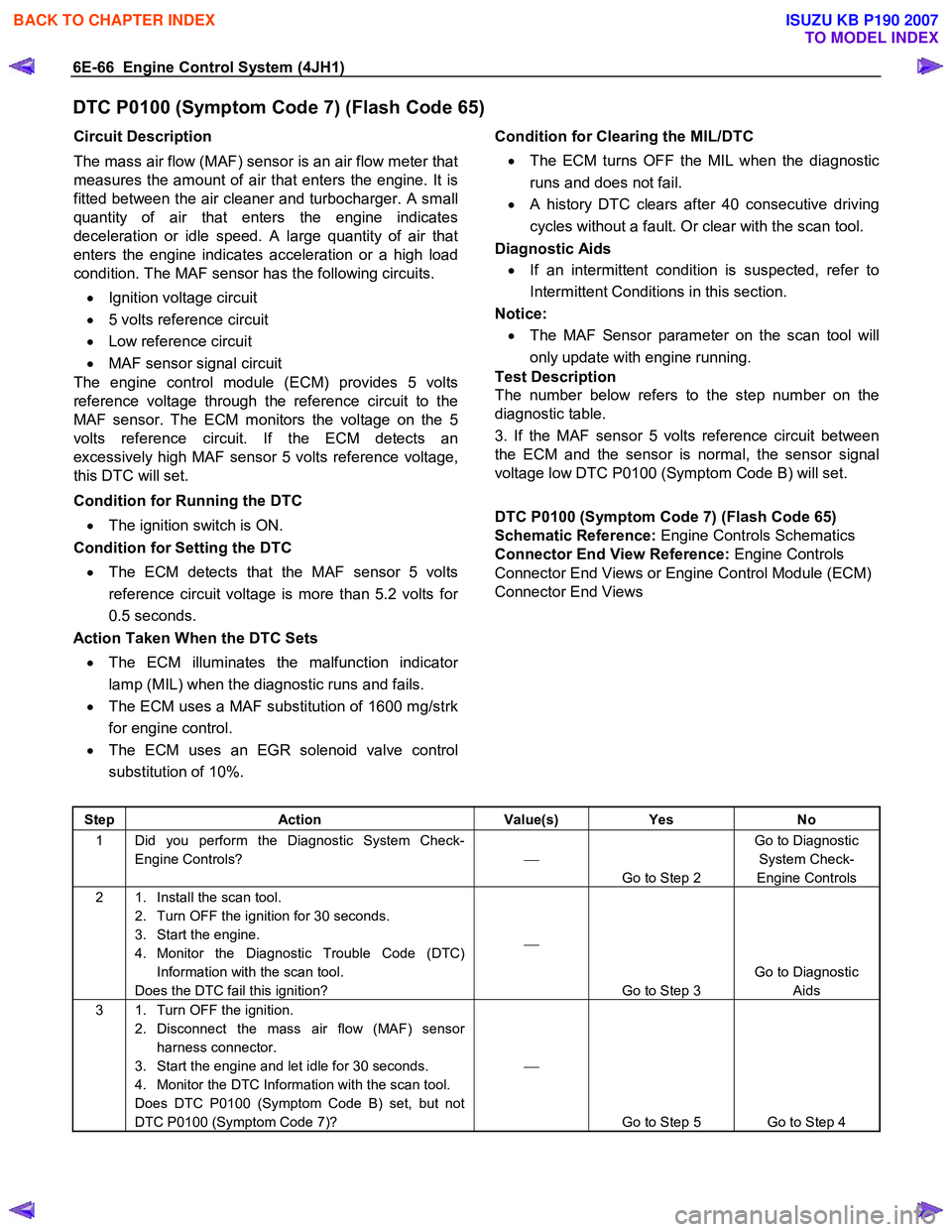
DTC P0100 (Symptom Code 7) (Flash Code 65)
Circuit Description
The mass air flow (MAF) sensor is an air flow meter that
measures the amount of air that enters the engine. It is
fitted between the air cleaner and turbocharger. A small
quantity of air that enters the engine indicates
deceleration or idle speed. A large quantity of air that
enters the engine indicates acceleration or a high load
condition. The MAF sensor has the following circuits.
• Ignition voltage circuit
• 5 volts reference circuit
• Low reference circuit
• MAF sensor signal circuit
The engine control module (ECM) provides 5 volts
reference voltage through the reference circuit to the
MAF sensor. The ECM monitors the voltage on the 5
volts reference circuit. If the ECM detects an
excessively high MAF sensor 5 volts reference voltage,
this DTC will set.
Condition for Running the DTC
• The ignition switch is ON.
Condition for Setting the DTC
• The ECM detects that the MAF sensor 5 volts
reference circuit voltage is more than 5.2 volts fo
r
0.5 seconds.
Action Taken When the DTC Sets
• The ECM illuminates the malfunction indicato
r
lamp (MIL) when the diagnostic runs and fails.
• The ECM uses a MAF substitution of 1600 mg/strk
for engine control.
• The ECM uses an EGR solenoid valve control
substitution of 10%.
Condition for Clearing the MIL/DTC
• The ECM turns OFF the MIL when the diagnostic
runs and does not fail.
• A history DTC clears after 40 consecutive driving
cycles without a fault. Or clear with the scan tool.
Diagnostic Aids
• If an intermittent condition is suspected, refer to
Intermittent Conditions in this section.
Notice: • The MAF Sensor parameter on the scan tool will
only update with engine running.
Test Description
The number below refers to the step number on the
diagnostic table.
3. If the MAF sensor 5 volts reference circuit between
the ECM and the sensor is normal, the sensor signal
voltage low DTC P0100 (Symptom Code B) will set.
DTC P0100 (Symptom Code 7) (Flash Code 65)
Schematic Reference: Engine Controls Schematics
Connector End View Reference: Engine Controls
Connector End Views or Engine Control Module (ECM)
Connector End Views
Step Action Value(s) Yes No
1 Did you perform the Diagnostic System Check-
Engine Controls?
Go to Step 2 Go to Diagnostic
System Check-
Engine Controls
2 1. Install the scan tool. 2. Turn OFF the ignition for 30 seconds.
3. Start the engine.
4. Monitor the Diagnostic Trouble Code (DTC) Information with the scan tool.
Does the DTC fail this ignition?
Go to Step 3 Go to Diagnostic
Aids
3 1. Turn OFF the ignition. 2. Disconnect the mass air flow (MAF) sensor harness connector.
3. Start the engine and let idle for 30 seconds.
4. Monitor the DTC Information with the scan tool.
Does DTC P0100 (Symptom Code B) set, but not
DTC P0100 (Symptom Code 7)?
Go to Step 5 Go to Step 4
BACK TO CHAPTER INDEX
TO MODEL INDEX
ISUZU KB P190 2007
Page 1102 of 6020
6E-68 Engine Control System (4JH1)
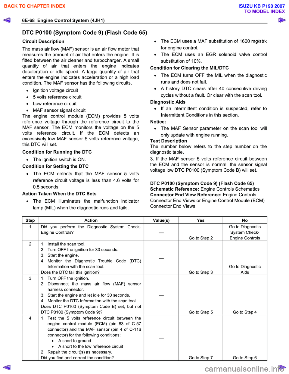
DTC P0100 (Symptom Code 9) (Flash Code 65)
Circuit Description
The mass air flow (MAF) sensor is an air flow meter that
measures the amount of air that enters the engine. It is
fitted between the air cleaner and turbocharger. A small
quantity of air that enters the engine indicates
deceleration or idle speed. A large quantity of air that
enters the engine indicates acceleration or a high load
condition. The MAF sensor has the following circuits.
• Ignition voltage circuit
• 5 volts reference circuit
• Low reference circuit
• MAF sensor signal circuit
The engine control module (ECM) provides 5 volts
reference voltage through the reference circuit to the
MAF sensor. The ECM monitors the voltage on the 5
volts reference circuit. If the ECM detects an
excessively low MAF sensor 5 volts reference voltage,
this DTC will set.
Condition for Running the DTC
• The ignition switch is ON.
Condition for Setting the DTC
• The ECM detects that the MAF sensor 5 volts
reference circuit voltage is less than 4.6 volts fo
r
0.5 seconds.
Action Taken When the DTC Sets
• The ECM illuminates the malfunction indicato
r
lamp (MIL) when the diagnostic runs and fails.
•
The ECM uses a MAF substitution of 1600 mg/strk
for engine control.
• The ECM uses an EGR solenoid valve control
substitution of 10%.
Condition for Clearing the MIL/DTC
• The ECM turns OFF the MIL when the diagnostic
runs and does not fail.
• A history DTC clears after 40 consecutive driving
cycles without a fault. Or clear with the scan tool.
Diagnostic Aids
• If an intermittent condition is suspected, refer to
Intermittent Conditions in this section.
Notice: • The MAF Sensor parameter on the scan tool will
only update with engine running.
Test Description
The number below refers to the step number on the
diagnostic table.
3. If the MAF sensor 5 volts reference circuit between
the ECM and the sensor is normal, the sensor signal
voltage low DTC P0100 (Symptom Code B) will set.
DTC P0100 (Symptom Code 9) (Flash Code 65)
Schematic Reference: Engine Controls Schematics
Connector End View Reference: Engine Controls
Connector End Views or Engine Control Module (ECM)
Connector End Views
Step Action Value(s) Yes No
1 Did you perform the Diagnostic System Check-
Engine Controls?
Go to Step 2 Go to Diagnostic
System Check-
Engine Controls
2 1. Install the scan tool. 2. Turn OFF the ignition for 30 seconds.
3. Start the engine.
4. Monitor the Diagnostic Trouble Code (DTC) Information with the scan tool.
Does the DTC fail this ignition?
Go to Step 3 Go to Diagnostic
Aids
3 1. Turn OFF the ignition. 2. Disconnect the mass air flow (MAF) sensor harness connector.
3. Start the engine and let idle for 30 seconds.
4. Monitor the DTC Information with the scan tool.
Does DTC P0100 (Symptom Code B) set, but not
DTC P0100 (Symptom Code 9)?
Go to Step 5 Go to Step 4
4 1. Test the 5 volts reference circuit between the engine control module (ECM) (pin 83 of C-57
connector) and the MAF sensor (pin 4 of C-116
connector) for the following conditions: • A short to ground
• A short to the low reference circuit
2. Repair the circuit(s) as necessary.
Did you find and correct the condition?
Go to Step 7 Go to Step 6
BACK TO CHAPTER INDEX
TO MODEL INDEX
ISUZU KB P190 2007
Page 1104 of 6020
6E-70 Engine Control System (4JH1)
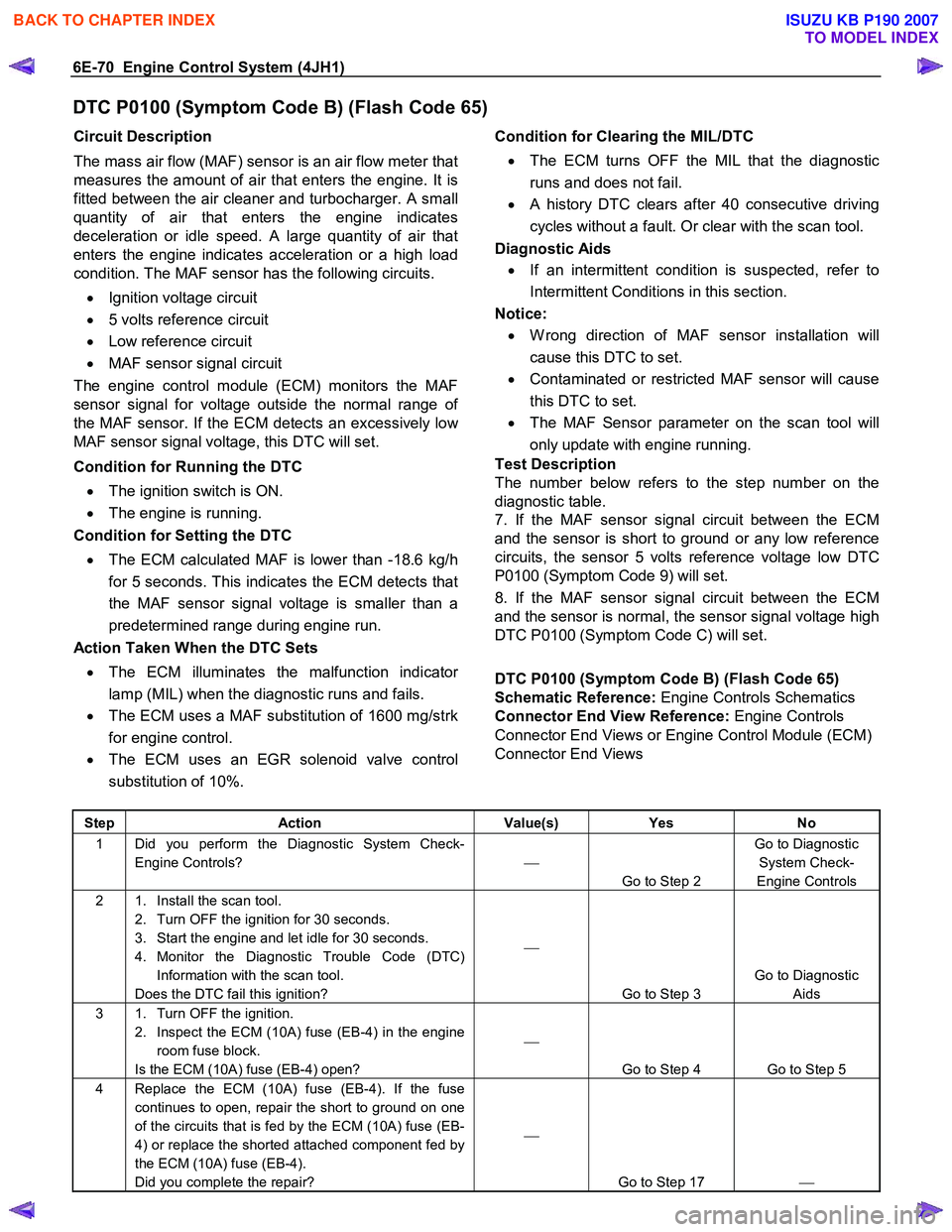
DTC P0100 (Symptom Code B) (Flash Code 65)
Circuit Description
The mass air flow (MAF) sensor is an air flow meter that
measures the amount of air that enters the engine. It is
fitted between the air cleaner and turbocharger. A small
quantity of air that enters the engine indicates
deceleration or idle speed. A large quantity of air that
enters the engine indicates acceleration or a high load
condition. The MAF sensor has the following circuits.
• Ignition voltage circuit
• 5 volts reference circuit
• Low reference circuit
• MAF sensor signal circuit
The engine control module (ECM) monitors the MAF
sensor signal for voltage outside the normal range o
f
the MAF sensor. If the ECM detects an excessively low
MAF sensor signal voltage, this DTC will set.
Condition for Running the DTC
• The ignition switch is ON.
• The engine is running.
Condition for Setting the DTC
• The ECM calculated MAF is lower than -18.6 kg/h
for 5 seconds. This indicates the ECM detects that
the MAF sensor signal voltage is smaller than a
predetermined range during engine run.
Action Taken When the DTC Sets
• The ECM illuminates the malfunction indicato
r
lamp (MIL) when the diagnostic runs and fails.
• The ECM uses a MAF substitution of 1600 mg/strk
for engine control.
• The ECM uses an EGR solenoid valve control
substitution of 10%.
Condition for Clearing the MIL/DTC
• The ECM turns OFF the MIL that the diagnostic
runs and does not fail.
• A history DTC clears after 40 consecutive driving
cycles without a fault. Or clear with the scan tool.
Diagnostic Aids
• If an intermittent condition is suspected, refer to
Intermittent Conditions in this section.
Notice: • W rong direction of MAF sensor installation will
cause this DTC to set.
• Contaminated or restricted MAF sensor will cause
this DTC to set.
• The MAF Sensor parameter on the scan tool will
only update with engine running.
Test Description
The number below refers to the step number on the
diagnostic table.
7. If the MAF sensor signal circuit between the ECM
and the sensor is short to ground or any low reference
circuits, the sensor 5 volts reference voltage low DTC
P0100 (Symptom Code 9) will set.
8. If the MAF sensor signal circuit between the ECM
and the sensor is normal, the sensor signal voltage high
DTC P0100 (Symptom Code C) will set.
DTC P0100 (Symptom Code B) (Flash Code 65)
Schematic Reference: Engine Controls Schematics
Connector End View Reference: Engine Controls
Connector End Views or Engine Control Module (ECM)
Connector End Views
Step Action Value(s) Yes No
1 Did you perform the Diagnostic System Check-
Engine Controls?
Go to Step 2 Go to Diagnostic
System Check-
Engine Controls
2 1. Install the scan tool. 2. Turn OFF the ignition for 30 seconds.
3. Start the engine and let idle for 30 seconds.
4. Monitor the Diagnostic Trouble Code (DTC) Information with the scan tool.
Does the DTC fail this ignition?
Go to Step 3 Go to Diagnostic
Aids
3 1. Turn OFF the ignition. 2. Inspect the ECM (10A) fuse (EB-4) in the engine room fuse block.
Is the ECM (10A) fuse (EB-4) open?
Go to Step 4 Go to Step 5
4 Replace the ECM (10A) fuse (EB-4). If the fuse continues to open, repair the short to ground on one
of the circuits that is fed by the ECM (10A) fuse (EB-
4) or replace the shorted attached component fed by
the ECM (10A) fuse (EB-4).
Did you complete the repair?
Go to Step 17
BACK TO CHAPTER INDEX
TO MODEL INDEX
ISUZU KB P190 2007
Page 1107 of 6020

Engine Control System (4JH1) 6E-73
DTC P0100 (Symptom Code C) (Flash Code 65)
Circuit Description
The mass air flow (MAF) sensor is an air flow meter that
measures the amount of air that enters the engine. It is
fitted between the air cleaner and turbocharger. A small
quantity of air that enters the engine indicates
deceleration or idle speed.
A large quantity of air that
enters the engine indicates acceleration or a high load
condition. The MAF sensor has the following circuits.
• Ignition voltage circuit
• 5 volts reference circuit
• Low reference circuit
• MAF sensor signal circuit
The engine control module (ECM) monitors the MAF
sensor signal for voltage outside the normal range o
f
the MAF sensor. If the ECM detects an excessively high
MAF sensor signal voltage, this DTC will set.
Condition for Running the DTC
• The ignition switch is ON.
• The engine is running.
Condition for Setting the DTC
• The ECM calculated MAF is higher than 984 kg/h
for 10 seconds. This indicates the ECM detects
that the MAF sensor signal voltage is higher than a
predetermined range during engine run.
Action Taken When the DTC Sets
• The ECM illuminates the malfunction indicato
r
lamp (MIL) when the diagnostic runs and fails.
• The ECM uses a MAF substitution of 1600 mg/strk
for engine control.
• The ECM uses an EGR solenoid valve control
substitution of 10%.
Condition for Clearing the MIL/DTC
• The ECM turns OFF the MIL when the diagnostic
runs and does not fail.
• A history DTC clears after 40 consecutive driving
cycles without a fault. Or clear with the scan tool.
Diagnostic Aids
• If an intermittent condition is suspected, refer to
Intermittent Conditions in this section.
Notice: • The MAF Sensor parameter on the scan tool will
only update with engine running.
Test Description
The number below refers to the step number on the
diagnostic table.
3. If the MAF sensor signal circuit between the ECM
and the sensor is normal, the sensor signal voltage lo
w
DTC P0100 (Symptom Code B) will set.
DTC P0100
(Symptom Code C) (Flash Code 65)
Schematic Reference: Engine Controls Schematics
Connector End View Reference: Engine Controls
Connector End Views or Engine Control Module (ECM)
Connector End Views
Step Action Value(s) Yes No
1 Did you perform the Diagnostic System Check-
Engine Controls?
Go to Step 2 Go to Diagnostic
System Check-
Engine Controls
2 1. Install the scan tool. 2. Turn OFF the ignition for 30 seconds.
3. Start the engine and let idle for 30 seconds.
4. Monitor the Diagnostic Trouble Code (DTC) Information with the scan tool.
Does the DTC fail this ignition?
Go to Step 3 Go to Diagnostic
Aids
3 1. Turn OFF the ignition. 2. Disconnect the mass air flow (MAF) sensor harness connector.
3. Start the engine and let idle for 30 seconds.
4. Monitor the DTC Information with the scan tool.
Does DTC P0100 (Symptom Code B) set, but not
DTC P0100 (Symptom Code C)?
Go to Step 4 Go to Step 5
BACK TO CHAPTER INDEX
TO MODEL INDEX
ISUZU KB P190 2007
Page 1109 of 6020
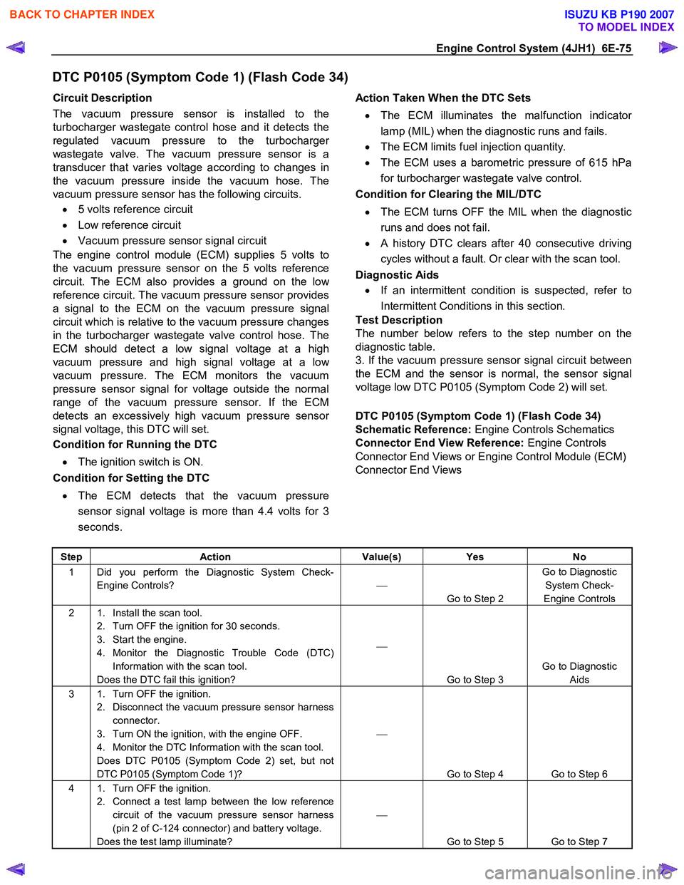
Engine Control System (4JH1) 6E-75
DTC P0105 (Symptom Code 1) (Flash Code 34)
Circuit Description
The vacuum pressure sensor is installed to the
turbocharger wastegate control hose and it detects the
regulated vacuum pressure to the turbocharge
r
wastegate valve. The vacuum pressure sensor is a
transducer that varies voltage according to changes in
the vacuum pressure inside the vacuum hose. The
vacuum pressure sensor has the following circuits.
• 5 volts reference circuit
• Low reference circuit
• Vacuum pressure sensor signal circuit
The engine control module (ECM) supplies 5 volts to
the vacuum pressure sensor on the 5 volts reference
circuit. The ECM also provides a ground on the lo
w
reference circuit. The vacuum pressure sensor provides
a signal to the ECM on the vacuum pressure signal
circuit which is relative to the vacuum pressure changes
in the turbocharger wastegate valve control hose. The
ECM should detect a low signal voltage at a high
vacuum pressure and high signal voltage at a lo
w
vacuum pressure. The ECM monitors the vacuum
pressure sensor signal for voltage outside the normal
range of the vacuum pressure sensor. If the ECM
detects an excessively high vacuum pressure senso
r
signal voltage, this DTC will set.
Condition for Running the DTC
• The ignition switch is ON.
Condition for Setting the DTC
• The ECM detects that the vacuum pressure
sensor signal voltage is more than 4.4 volts for 3
seconds.
Action Taken When the DTC Sets
• The ECM illuminates the malfunction indicato
r
lamp (MIL) when the diagnostic runs and fails.
• The ECM limits fuel injection quantity.
• The ECM uses a barometric pressure of 615 hPa
for turbocharger wastegate valve control.
Condition for Clearing the MIL/DTC
• The ECM turns OFF the MIL when the diagnostic
runs and does not fail.
• A history DTC clears after 40 consecutive driving
cycles without a fault. Or clear with the scan tool.
Diagnostic Aids
• If an intermittent condition is suspected, refer to
Intermittent Conditions in this section.
Test Description
The number below refers to the step number on the
diagnostic table.
3. If the vacuum pressure sensor signal circuit between
the ECM and the sensor is normal, the sensor signal
voltage low DTC P0105 (Symptom Code 2) will set.
DTC P0105 (Symptom Code 1) (Flash Code 34)
Schematic Reference: Engine Controls Schematics
Connector End View Reference: Engine Controls
Connector End Views or Engine Control Module (ECM)
Connector End Views
Step Action Value(s) Yes No
1 Did you perform the Diagnostic System Check-
Engine Controls?
Go to Step 2 Go to Diagnostic
System Check-
Engine Controls
2 1. Install the scan tool. 2. Turn OFF the ignition for 30 seconds.
3. Start the engine.
4. Monitor the Diagnostic Trouble Code (DTC) Information with the scan tool.
Does the DTC fail this ignition?
Go to Step 3 Go to Diagnostic
Aids
3 1. Turn OFF the ignition. 2. Disconnect the vacuum pressure sensor harness connector.
3. Turn ON the ignition, with the engine OFF.
4. Monitor the DTC Information with the scan tool.
Does DTC P0105 (Symptom Code 2) set, but not
DTC P0105 (Symptom Code 1)?
Go to Step 4 Go to Step 6
4 1. Turn OFF the ignition. 2. Connect a test lamp between the low reference circuit of the vacuum pressure sensor harness
(pin 2 of C-124 connector) and battery voltage.
Does the test lamp illuminate?
Go to Step 5 Go to Step 7
BACK TO CHAPTER INDEX
TO MODEL INDEX
ISUZU KB P190 2007
Page 1112 of 6020
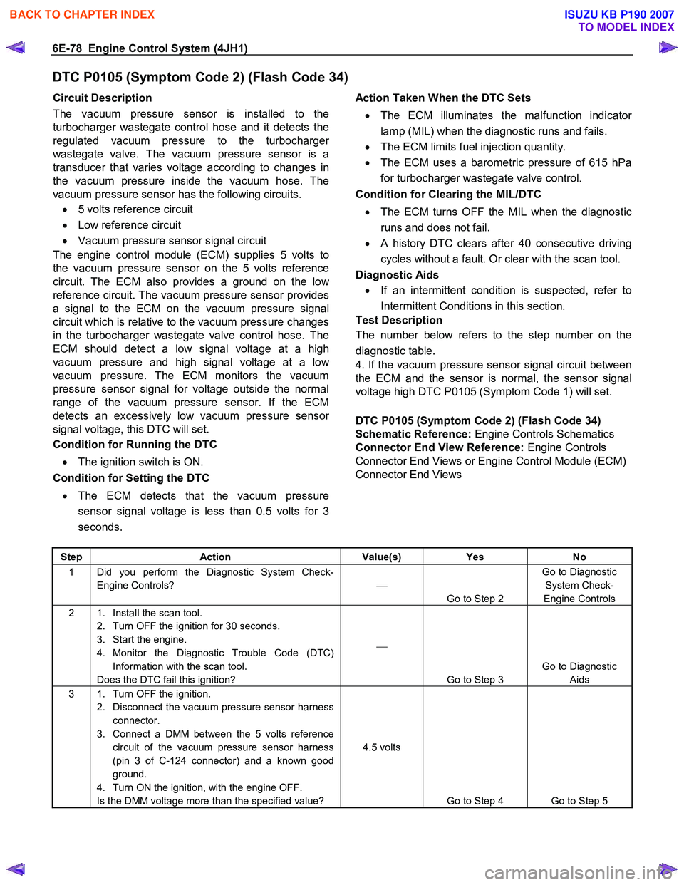
6E-78 Engine Control System (4JH1)
DTC P0105 (Symptom Code 2) (Flash Code 34)
Circuit Description
The vacuum pressure sensor is installed to the
turbocharger wastegate control hose and it detects the
regulated vacuum pressure to the turbocharge
r
wastegate valve. The vacuum pressure sensor is a
transducer that varies voltage according to changes in
the vacuum pressure inside the vacuum hose. The
vacuum pressure sensor has the following circuits.
• 5 volts reference circuit
• Low reference circuit
• Vacuum pressure sensor signal circuit
The engine control module (ECM) supplies 5 volts to
the vacuum pressure sensor on the 5 volts reference
circuit. The ECM also provides a ground on the lo
w
reference circuit. The vacuum pressure sensor provides
a signal to the ECM on the vacuum pressure signal
circuit which is relative to the vacuum pressure changes
in the turbocharger wastegate valve control hose. The
ECM should detect a low signal voltage at a high
vacuum pressure and high signal voltage at a lo
w
vacuum pressure. The ECM monitors the vacuum
pressure sensor signal for voltage outside the normal
range of the vacuum pressure sensor. If the ECM
detects an excessively low vacuum pressure senso
r
signal voltage, this DTC will set.
Condition for Running the DTC
• The ignition switch is ON.
Condition for Setting the DTC
• The ECM detects that the vacuum pressure
sensor signal voltage is less than 0.5 volts for 3
seconds.
Action Taken When the DTC Sets
• The ECM illuminates the malfunction indicato
r
lamp (MIL) when the diagnostic runs and fails.
• The ECM limits fuel injection quantity.
• The ECM uses a barometric pressure of 615 hPa
for turbocharger wastegate valve control.
Condition for Clearing the MIL/DTC
• The ECM turns OFF the MIL when the diagnostic
runs and does not fail.
• A history DTC clears after 40 consecutive driving
cycles without a fault. Or clear with the scan tool.
Diagnostic Aids
• If an intermittent condition is suspected, refer to
Intermittent Conditions in this section.
Test Description
The number below refers to the step number on the
diagnostic table.
4. If the vacuum pressure sensor signal circuit between
the ECM and the sensor is normal, the sensor signal
voltage high DTC P0105 (Symptom Code 1) will set.
DTC P0105 (Symptom Code 2) (Flash Code 34)
Schematic Reference: Engine Controls Schematics
Connector End View Reference: Engine Controls
Connector End Views or Engine Control Module (ECM)
Connector End Views
Step Action Value(s) Yes No
1 Did you perform the Diagnostic System Check-
Engine Controls?
Go to Step 2 Go to Diagnostic
System Check-
Engine Controls
2 1. Install the scan tool. 2. Turn OFF the ignition for 30 seconds.
3. Start the engine.
4. Monitor the Diagnostic Trouble Code (DTC) Information with the scan tool.
Does the DTC fail this ignition?
Go to Step 3 Go to Diagnostic
Aids
3 1. Turn OFF the ignition. 2. Disconnect the vacuum pressure sensor harness connector.
3. Connect a DMM between the 5 volts reference circuit of the vacuum pressure sensor harness
(pin 3 of C-124 connector) and a known good
ground.
4. Turn ON the ignition, with the engine OFF.
Is the DMM voltage more than the specified value? 4.5 volts
Go to Step 4 Go to Step 5
BACK TO CHAPTER INDEX
TO MODEL INDEX
ISUZU KB P190 2007
Page 1115 of 6020
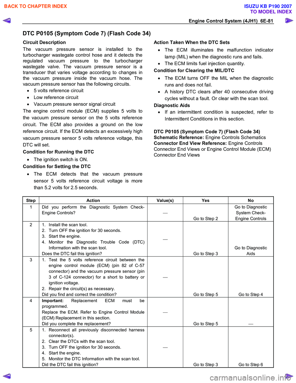
Engine Control System (4JH1) 6E-81
DTC P0105 (Symptom Code 7) (Flash Code 34)
Circuit Description
The vacuum pressure sensor is installed to the
turbocharger wastegate control hose and it detects the
regulated vacuum pressure to the turbocharge
r
wastegate valve. The vacuum pressure sensor is a
transducer that varies voltage according to changes in
the vacuum pressure inside the vacuum hose. The
vacuum pressure sensor has the following circuits.
• 5 volts reference circuit
• Low reference circuit
• Vacuum pressure sensor signal circuit
The engine control module (ECM) supplies 5 volts to
the vacuum pressure sensor on the 5 volts reference
circuit. The ECM also provides a ground on the lo
w
reference circuit. If the ECM detects an excessively high
vacuum pressure sensor 5 volts reference voltage, this
DTC will set.
Condition for Running the DTC
• The ignition switch is ON.
Condition for Setting the DTC
• The ECM detects that the vacuum pressure
sensor 5 volts reference circuit voltage is more
than 5.2 volts for 2.5 seconds.
Action Taken When the DTC Sets
• The ECM illuminates the malfunction indicato
r
lamp (MIL) when the diagnostic runs and fails.
• The ECM limits fuel injection quantity.
Condition for Clearing the MIL/DTC
• The ECM turns OFF the MIL when the diagnostic
runs and does not fail.
• A history DTC clears after 40 consecutive driving
cycles without a fault. Or clear with the scan tool.
Diagnostic Aids
• If an intermittent condition is suspected, refer to
Intermittent Conditions in this section.
DTC P0105 (Symptom Code 7) (Flash Code 34)
Schematic Reference: Engine Controls Schematics
Connector End View Reference: Engine Controls
Connector End Views or Engine Control Module (ECM)
Connector End Views
Step Action Value(s) Yes No
1 Did you perform the Diagnostic System Check-
Engine Controls?
Go to Step 2 Go to Diagnostic
System Check-
Engine Controls
2 1. Install the scan tool. 2. Turn OFF the ignition for 30 seconds.
3. Start the engine.
4. Monitor the Diagnostic Trouble Code (DTC) Information with the scan tool.
Does the DTC fail this ignition?
Go to Step 3 Go to Diagnostic
Aids
3 1. Test the 5 volts reference circuit between the engine control module (ECM) (pin 82 of C-57
connector) and the vacuum pressure sensor (pin
3 of C-124 connector) for a short to battery or
ignition voltage.
2. Repair the circuit(s) as necessary.
Did you find and correct the condition?
Go to Step 5 Go to Step 4
4 Important: Replacement ECM must be
programmed.
Replace the ECM. Refer to Engine Control Module
(ECM) Replacement in this section.
Did you complete the replacement?
Go to Step 5
5 1. Reconnect all previously disconnected harness
connector(s).
2. Clear the DTCs with the scan tool.
3. Turn OFF the ignition for 30 seconds.
4. Start the engine.
5. Monitor the DTC Information with the scan tool.
Did the DTC fail this ignition?
Go to Step 3 Go to Step 6
BACK TO CHAPTER INDEX
TO MODEL INDEX
ISUZU KB P190 2007