2007 ISUZU KB P190 turbo
[x] Cancel search: turboPage 1971 of 6020
6E-354 ENGINE CONTROL SYSTEM (4JK1/4JJ1)
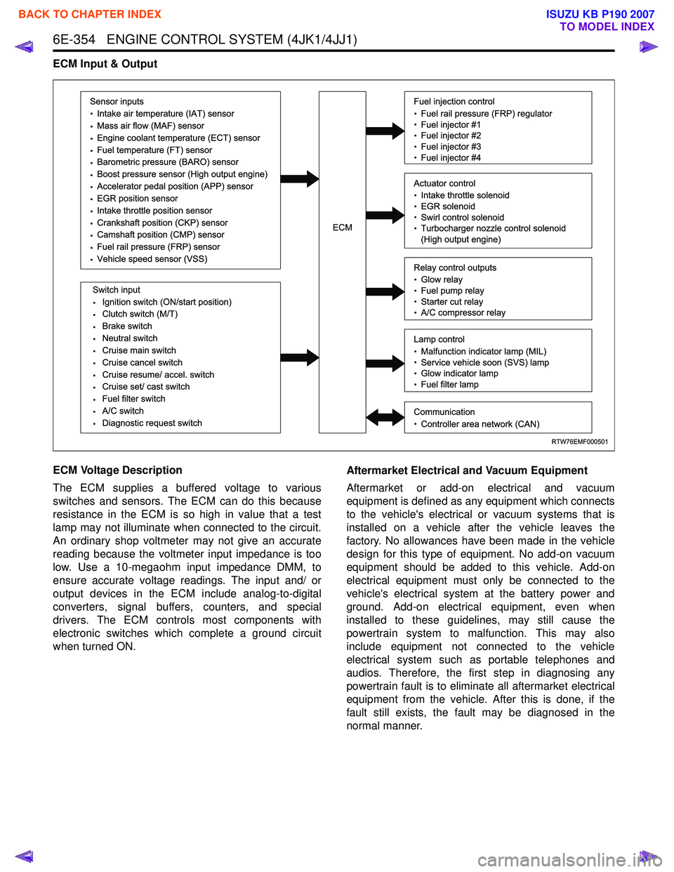
ECM Input & Output
ECM Voltage Description
The ECM supplies a buffered voltage to various
switches and sensors. The ECM can do this because
resistance in the ECM is so high in value that a test
lamp may not illuminate when connected to the circuit.
An ordinary shop voltmeter may not give an accurate
reading because the voltmeter input impedance is too
low. Use a 10-megaohm input impedance DMM, to
ensure accurate voltage readings. The input and/ or
output devices in the ECM include analog-to-digital
converters, signal buffers, counters, and special
drivers. The ECM controls most components with
electronic switches which complete a ground circuit
when turned ON. Aftermarket Electrical and Vacuum Equipment
Aftermarket or add-on electrical and vacuum
equipment is defined as any equipment which connects
to the vehicle's electrical or vacuum systems that is
installed on a vehicle after the vehicle leaves the
factory. No allowances have been made in the vehicle
design for this type of equipment. No add-on vacuum
equipment should be added to this vehicle. Add-on
electrical equipment must only be connected to the
vehicle's electrical system at the battery power and
ground. Add-on electrical equipment, even when
installed to these guidelines, may still cause the
powertrain system to malfunction. This may also
include equipment not connected to the vehicle
electrical system such as portable telephones and
audios. Therefore, the first step in diagnosing any
powertrain fault is to eliminate all aftermarket electrical
equipment from the vehicle. After this is done, if the
fault still exists, the fault may be diagnosed in the
normal manner.
RTW76EMF000501
Sensor inputs
· Intake air temperature (IAT) sensor
· Mass air flow (MAF) sensor
· Engine coolant temperature (ECT) sensor
· Fuel temperature (FT) sensor
· Barometric pressure (BARO) sensor
· Boost pressure sensor (High output engine)
· Accelerator pedal position (APP) sensor
· EGR position sensor
· Intake throttle position sensor
· Crankshaft position (CKP) sensor
· Camshaft position (CMP) sensor
· Fuel rail pressure (FRP) sensor
· Vehicle speed sensor (VSS)
Switch input
· Ignition switch (ON/start position)
· Clutch switch (M/T)
· Brake switch
· Neutral switch
· Cruise main switch
· Cruise cancel switch
· Cruise resume/ accel. switch
· Cruise set/ cast switch
· Fuel filter switch
· A/C switch
· Diagnostic request switch
Fuel injection control
· Fuel rail pressure (FRP) regulator
· Fuel injector #1
· Fuel injector #2
· Fuel injector #3
· Fuel injector #4
Relay control outputs
· Glow relay
· Fuel pump relay
· Starter cut relay
· A/C compressor relay
Lamp control
· Malfunction indicator lamp (MIL)
· Service vehicle soon (SVS) lamp
· Glow indicator lamp
· Fuel filter lamp
Communication
· Controller area network (CAN)
Actuator control
· Intake throttle solenoid
· EGR solenoid
· Swirl control solenoid
· Turbocharger nozzle control solenoid
(High output engine)ECM
BACK TO CHAPTER INDEX
TO MODEL INDEX
ISUZU KB P190 2007
Page 1975 of 6020
6E-358 ENGINE CONTROL SYSTEM (4JK1/4JJ1)
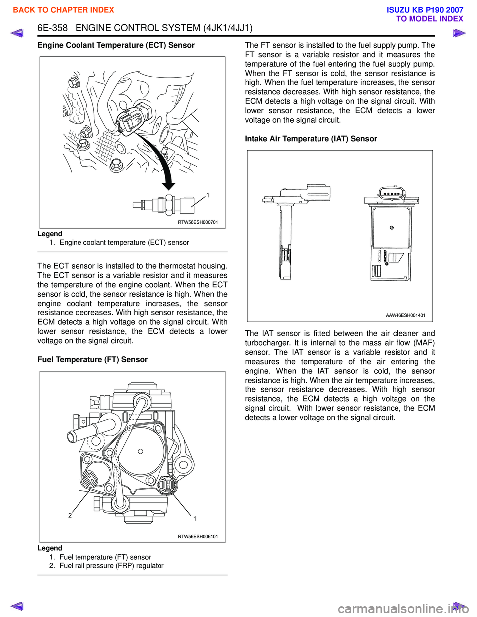
Engine Coolant Temperature (ECT) Sensor
Legend1. Engine coolant temperature (ECT) sensor
The ECT sensor is installed to the thermostat housing.
The ECT sensor is a variable resistor and it measures
the temperature of the engine coolant. When the ECT
sensor is cold, the sensor resistance is high. When the
engine coolant temperature increases, the sensor
resistance decreases. With high sensor resistance, the
ECM detects a high voltage on the signal circuit. With
lower sensor resistance, the ECM detects a lower
voltage on the signal circuit.
Fuel Temperature (FT) Sensor
Legend 1. Fuel temperature (FT) sensor
2. Fuel rail pressure (FRP) regulator
The FT sensor is installed to the fuel supply pump. The
FT sensor is a variable resistor and it measures the
temperature of the fuel entering the fuel supply pump.
When the FT sensor is cold, the sensor resistance is
high. When the fuel temperature increases, the sensor
resistance decreases. With high sensor resistance, the
ECM detects a high voltage on the signal circuit. With
lower sensor resistance, the ECM detects a lower
voltage on the signal circuit.
Intake Air Temperature (IAT) Sensor
The IAT sensor is fitted between the air cleaner and
turbocharger. It is internal to the mass air flow (MAF)
sensor. The IAT sensor is a variable resistor and it
measures the temperature of the air entering the
engine. When the IAT sensor is cold, the sensor
resistance is high. When the air temperature increases,
the sensor resistance decreases. With high sensor
resistance, the ECM detects a high voltage on the
signal circuit. With lower sensor resistance, the ECM
detects a lower voltage on the signal circuit.
RTW56ESH000701
1
RTW56ESH006101
12
AAW46ESH001401
BACK TO CHAPTER INDEX
TO MODEL INDEX
ISUZU KB P190 2007
Page 1976 of 6020
ENGINE CONTROL SYSTEM (4JK1/4JJ1) 6E-359
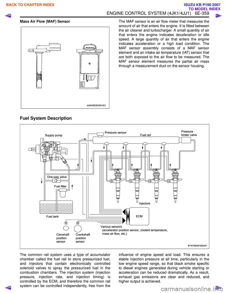
Mass Air Flow (MAF) SensorThe MAF sensor is an air flow meter that measures the
amount of air that enters the engine. It is fitted between
the air cleaner and turbocharger. A small quantity of air
that enters the engine indicates deceleration or idle
speed. A large quantity of air that enters the engine
indicates acceleration or a high load condition. The
MAF sensor assembly consists of a MAF sensor
element and an intake air temperature (IAT) sensor that
are both exposed to the air flow to be measured. The
MAF sensor element measures the partial air mass
through a measurement duct on the sensor housing.
Fuel System Description
The common rail system uses a type of accumulator
chamber called the fuel rail to store pressurized fuel,
and injectors that contain electronically controlled
solenoid valves to spray the pressurized fuel in the
combustion chambers. The injection system (injection
pressure, injection rate, and injection timing) is
controlled by the ECM, and therefore the common rail
system can be controlled independently, free from the influence of engine speed and load. This ensures a
stable injection pressure at all time, particularly in the
low engine speed range, so that black smoke specific
to diesel engines generated during vehicle starting or
acceleration can be reduced dramatically. As a result,
exhaust gas emissions are clear and reduced, and
higher output is achieved.
AAW46ESH001401
RTW76EMF000401
Supply pump
One-way valve
Fuel tank Fuel filter
Camshaft
position
sensor Crankshaft
position
sensor Various sensors
(accelerator position sensor, coolant temperature,
mass air flow, etc.) Injectors
Pressure sensor
Fuel rail Pressure
limiter valve
ECM
BACK TO CHAPTER INDEX
TO MODEL INDEX
ISUZU KB P190 2007
Page 1983 of 6020
6E-366 ENGINE CONTROL SYSTEM (4JK1/4JJ1)
The EGR valve is mounted on the intake manifold. The
ECM controls the EGR valve opening based on the
engine running condition. The ECM controls the EGR
valve by controlling the solenoid. The solenoid is
controlled based on pulse width modulation (PWM)
signal sent from the ECM. A duty ratio change 0% to
appropriate percentage is EGR valve lift control. To
open the valve, duty ratio is increased. To close the
valve, duty ratio becomes small.
The EGR valve position is detected by the position
sensor, and relayed to the ECM. The position sensor
provides a signal to the ECM on the signal circuit,
which is relative to the position changes of the EGR
valve. The ECM should detect a low signal voltage at a
small lift amount or closed position. The ECM should
detect high signal voltage at a large lift amount.
Intake Throttle Valve
The intake throttle valve is located on the intake
manifold inlet. The ECM controls the intake throttle
valve opening based on the engine running condition.
The ECM controls the intake throttle valve by
controlling the solenoid. The solenoid is controlled
based on pulse width modulation (PWM) signal sent
from the ECM. A duty ratio change 0% to appropriate
percentage is intake throttle valve opening angle
control. To open the valve, duty ratio is increased. To
close the valve, duty ratio becomes small.
The intake throttle valve position is detected by the
position sensor, and relayed to the ECM. The position
sensor provides a signal to the ECM on the signal
circuit, which is relative to the position changes of the
intake throttle valve. The ECM should detect a low
signal voltage at a small opening amount or closed
position. The ECM should detect high signal voltage at
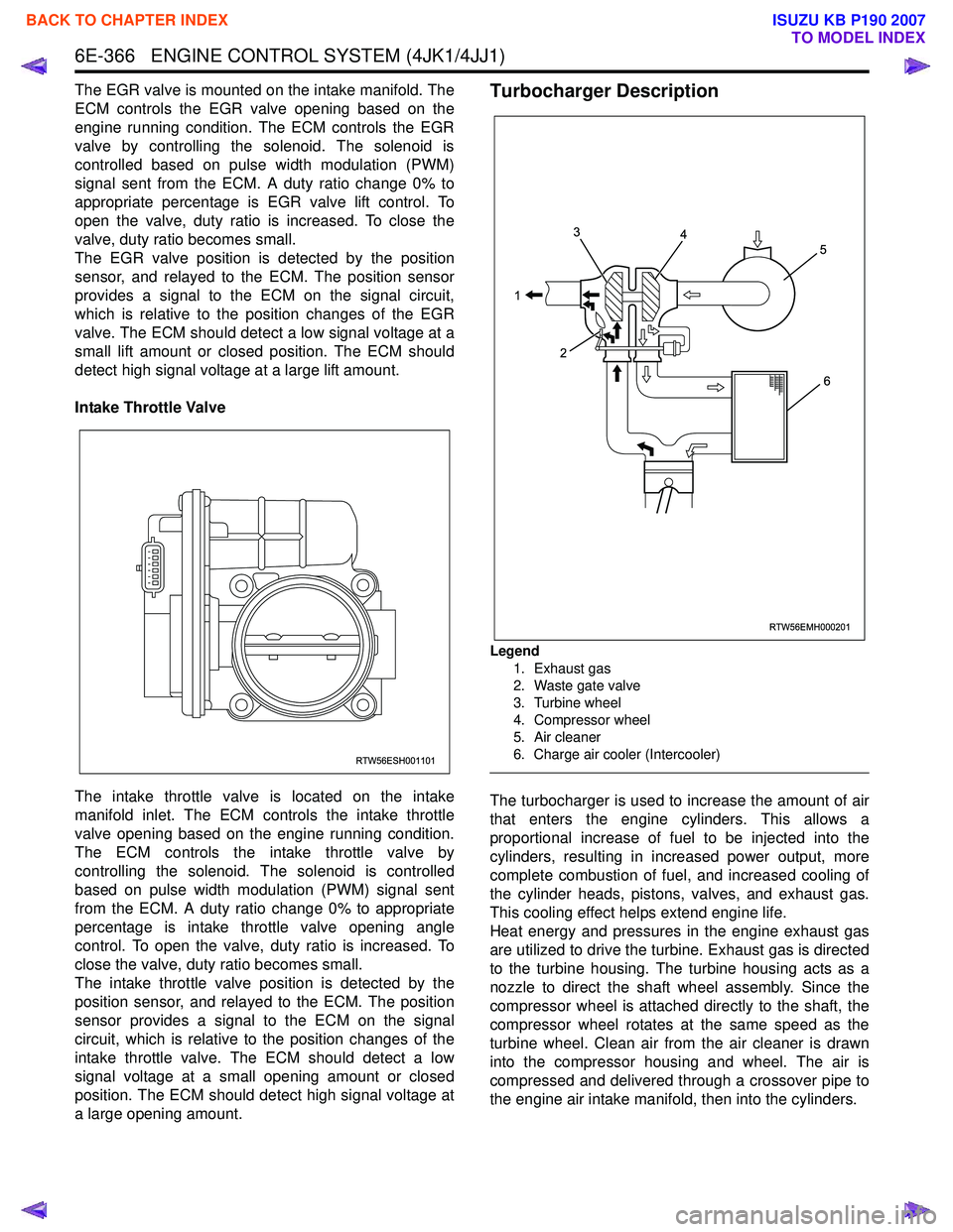
a large opening amount.Turbocharger Description
Legend
1. Exhaust gas
2. Waste gate valve
3. Turbine wheel
4. Compressor wheel
5. Air cleaner
6. Charge air cooler (Intercooler)
The turbocharger is used to increase the amount of air
that enters the engine cylinders. This allows a
proportional increase of fuel to be injected into the
cylinders, resulting in increased power output, more
complete combustion of fuel, and increased cooling of
the cylinder heads, pistons, valves, and exhaust gas.
This cooling effect helps extend engine life.
Heat energy and pressures in the engine exhaust gas
are utilized to drive the turbine. Exhaust gas is directed
to the turbine housing. The turbine housing acts as a
nozzle to direct the shaft wheel assembly. Since the
compressor wheel is attached directly to the shaft, the
compressor wheel rotates at the same speed as the
turbine wheel. Clean air from the air cleaner is drawn
into the compressor housing and wheel. The air is
compressed and delivered through a crossover pipe to
the engine air intake manifold, then into the cylinders.
RTW56ESH001101
RTW56EMH000201
1 3
2 4
5
6
BACK TO CHAPTER INDEX
TO MODEL INDEX
ISUZU KB P190 2007
Page 1984 of 6020
ENGINE CONTROL SYSTEM (4JK1/4JJ1) 6E-367
The amount of air pressure rise and air volume
delivered to the engine from the compressor outlet is
regulated by a waste gate valve in the exhaust housing.
The position of the waste gate valve is controlled by the
amount of pressure built up on the intake side of the
turbocharger. The diaphragm on the inside of the waste
gate is pressure sensitive, and controls the position of
the valve inside the turbocharger. The position of the
valve will increase or decrease the amount of boost to
the turbocharger. (Standard output engine)
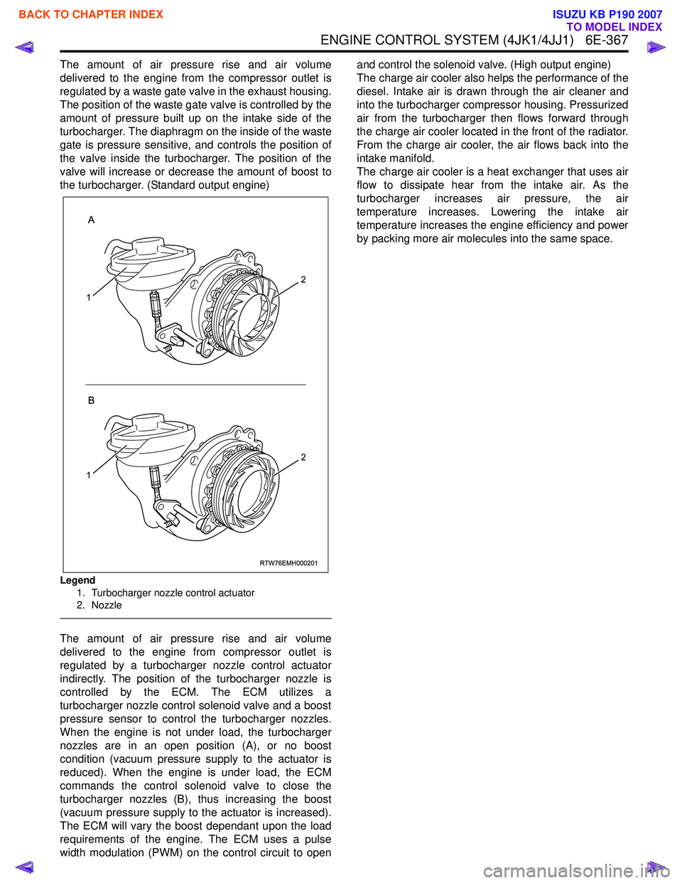
Legend
1. Turbocharger nozzle control actuator
2. Nozzle
The amount of air pressure rise and air volume
delivered to the engine from compressor outlet is
regulated by a turbocharger nozzle control actuator
indirectly. The position of the turbocharger nozzle is
controlled by the ECM. The ECM utilizes a
turbocharger nozzle control solenoid valve and a boost
pressure sensor to control the turbocharger nozzles.
When the engine is not under load, the turbocharger
nozzles are in an open position (A), or no boost
condition (vacuum pressure supply to the actuator is
reduced). When the engine is under load, the ECM
commands the control solenoid valve to close the
turbocharger nozzles (B), thus increasing the boost
(vacuum pressure supply to the actuator is increased).
The ECM will vary the boost dependant upon the load
requirements of the engine. The ECM uses a pulse
width modulation (PWM) on the control circuit to open and control the solenoid valve. (High output engine)
The charge air cooler also helps the performance of the
diesel. Intake air is drawn through the air cleaner and
into the turbocharger compressor housing. Pressurized
air from the turbocharger then flows forward through
the charge air cooler located in the front of the radiator.
From the charge air cooler, the air flows back into the
intake manifold.
The charge air cooler is a heat exchanger that uses air
flow to dissipate hear from the intake air. As the
turbocharger increases air pressure, the air
temperature increases. Lowering the intake air
temperature increases the engine efficiency and power
by packing more air molecules into the same space.
RTW76EMH000201
A
B
1
2
1
2
BACK TO CHAPTER INDEX
TO MODEL INDEX
ISUZU KB P190 2007
Page 5561 of 6020
ELECTRICAL-BODY AND CHASSIS 8A-623
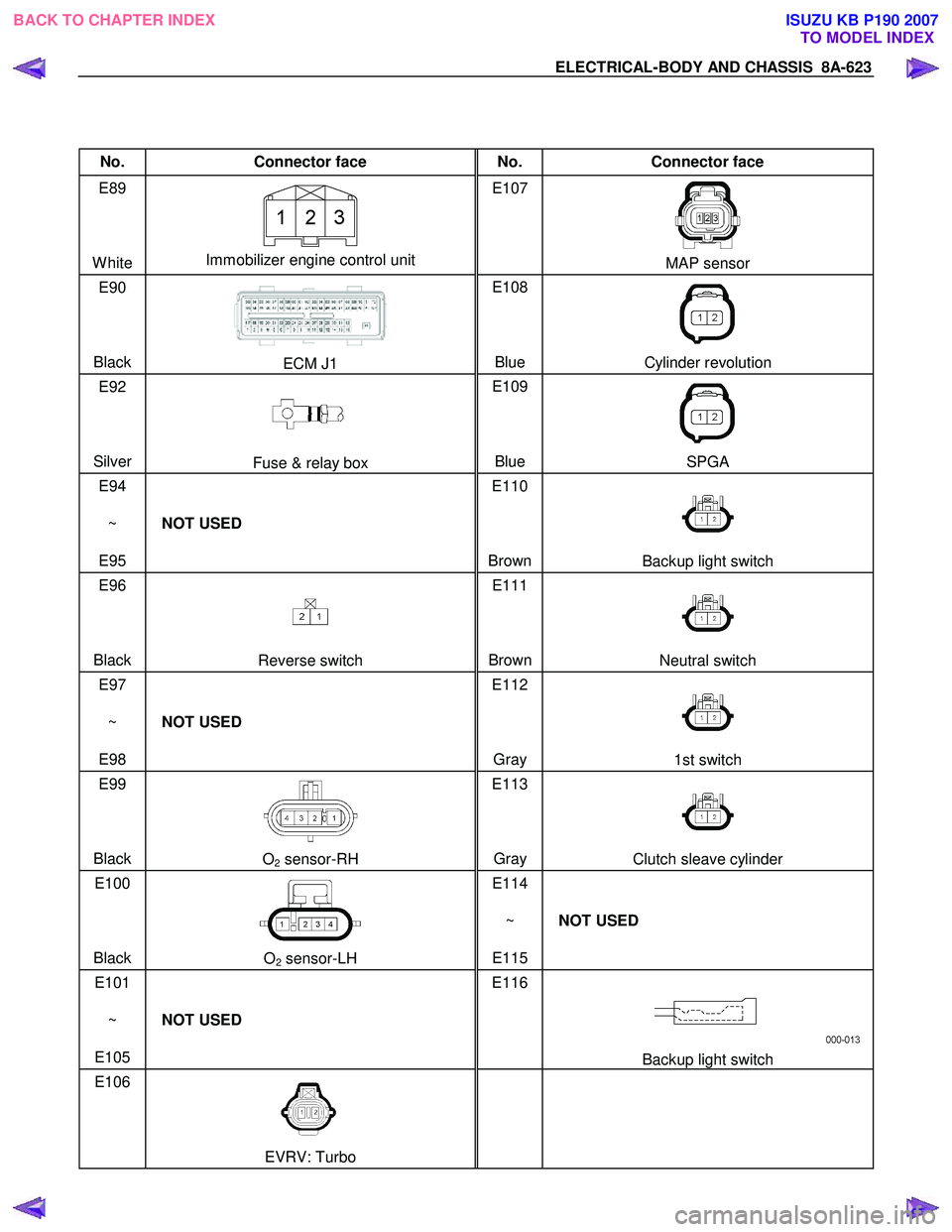
No. Connector face No. Connector face
E89
White
Immobilizer engine control unit E107
MAP sensor
E90
Black
ECM J1 E108
Blue Cylinder revolution
E92
Silver
Fuse & relay box E109
Blue SPGA
E94
~
E95 NOT USED E110
Brown
Backup light switch
E96
Black
Reverse switch E111
BrownNeutral switch
E97
~
E98 NOT USED E112
Gray
1st switch
E99
Black
O2 sensor-RH E113
Gray Clutch sleave cylinder
E100
Black
O2 sensor-LH E114
~
E115 NOT USED
E101
~
E105 NOT USED E116
Backup light switch
E106
EVRV: Turbo
BACK TO CHAPTER INDEX
TO MODEL INDEXISUZU KB P190 2007