2007 ISUZU KB P190 indicator
[x] Cancel search: indicatorPage 893 of 6020

6A – 88 ENGINE MECHANICAL
4. Visually inspect the piston rings.
If a piston ring groove is damaged or distorted, the piston
must be replaced.
Piston Pin Diameter
Use a micrometer to measure the piston pin diameter at
several points.
If the measured value is less than the specified limit, the piston
pin must be replaced.
Piston Pin Diameter mm
(in)
Standard Limit
30.995-31.000
(1.2202-1.2204) 30.97
(1.2193)
Piston Pin and Piston Clearance
Use and inside dial indicator to measure the piston pin hole (in
the piston).
Piston Pin Hole mm
(in)
4JA1T (L) 31.002-31.010 (1.2206-1.2208)
4JA1TC, 4JH1TC 31.005-31.013 (1.2207-1.2210)
Piston Pin and Piston Pin Hole Clearance mm (in)
4JA1T (L) 0.002-0.015 (0.00008-0.0006)
4JA1TC, 4JH1TC 0.005-0.018 (0.0002-0.0007)
CYLINDER HEAD GASKET SELECTION
Cylinder head gasket is determined by the piston head
projection from the cylinder body upper surface, in order to
improve engine performance.
Three types of gasket are provided by the difference of
thickness. Select the adequet one out of three grades of
gasket, according to the following procedure.
Before measurement, clear off carbon from the piston head
and cylinder body surface and also clean the place where a
gasket was installed.
015LX026
015RW048
011LX011
BACK TO CHAPTER INDEX
TO MODEL INDEX
ISUZU KB P190 2007
Page 894 of 6020

ENGINE MECHANICAL 6A – 89
RTW36ASH001701
Piston Head Projection Measuring Point
1. Use a dial indicator to measure the piston projection
amount.
2. Refer to the illustration for the piston head projection measuring positions.
All measuring positions should be as close as possible to
the cylinder liner.
3. Measure the points 1, 2, 3, 4 and obtain two differences 1- 2 and 3-4 on each cylinder.
Calculate the average value of the piston head projection
on each cylinder.
4. Obtain the maximum value in the four cylinders.
5. Determine the gasket grade required to the maximum value described above in accordance with the following
table.
Cylinder Head Gasket Combination mm (in)
Cylinder Head Gasket Combination
4JA1T (L), 4JA1TC mm (in)
Gasket Grade Mark Piston Projection Gasket Thickness
(Reference)
A 0.718-0.773
(0.0283-0.0304) 1.6
(0.0630)
B 0.773-0.819
(0.0304-0.0322) 1.65
(0.0650)
C 0.819-0.874
(0.0322-0.0344) 1.70
(0.0669)
4JH1TC mm (in)
Gasket Grade Mark Piston Projection Gasket Thickness
(Reference)
A 0.215-0.265
(0.0085-0.0104) 1.3
(0.5118)
B 0.265-0.315
(0.0104-0.0124) 1.35
(0.5315)
C 0.315-0.365
(0.0124-0.0144) 1.4
(0.5512)
NOTE:
Difference of the each piston projection and must be
equal or within 0.1 mm (0.004 in).
011RY00027
011RY00030
BACK TO CHAPTER INDEX
TO MODEL INDEX
ISUZU KB P190 2007
Page 895 of 6020

6A – 90 ENGINE MECHANICAL
CONNECTING ROD
Connecting Rod Alignment
Use a connecting rod aligner to measure the distortion and the
parallelism between the connecting rod big end hole and the
connecting rod small end hole.
If either the measured distortion or parallelism exceed the
specified limit, the connecting rod must be replaced.
Connecting Rod Alignment Per Length of 100 mm (3.94 in)
mm (in)
Standard Limit
Distortion 0.08 (0.003) or Less 0.20 (0.008)
Parallelism 0.05 (0.002) or Less 0.15 (0.006)
Connecting Rod Side Face Clearance
1. Install the connecting rod to the crankpin.
2. Use a feeler gauge to measure the clearance between the connecting rod big end side face and the crankpin side
face.
If the measured value exceeds the specified limit, the
connecting rod must be replaced.
Connecting Rod Big End and Crankpin Side Face Clearance
mm (in)
Standard Limit
0.23 (0.009) 0.35 (0.014)
Piston Pin and Connecting Rod Small End
Bushing Clearance
Use a caliper calibrator and a dial indicator to measure the
piston pin and connecting rod small end bushing clearance.
If the clearance between the piston pin and the connecting rod
small end bushing exceeds the specified limit, replace the
piston pin and/or the connecting rod.
Piston Pin and Connecting Rod Small End
Bushing Clearance mm (in)
Standard Limit
4JA1T (L) 0.008-0.020
(0.003-0.0008) 0.050 (0.002)
4JA1TC,
4JH1TC 0.005-0.018
(0.0002-0.0007) 0.050 (0.002)
015LX034
011RY00029 015LX028
BACK TO CHAPTER INDEX
TO MODEL INDEX
ISUZU KB P190 2007
Page 896 of 6020

ENGINE MECHANICAL 6A – 91
IDLER GEAR SHAFT AND IDLER GEAR
Idler Gear "A" Shaft Outside Diameter
Use a micrometer to measure the idler gear shaft outside
diameter.
If the measured value is less than the specified limit, the idler
gear shaft must be replaced.
Idler Gear "A" Shaft Outside Diameter mm (in)
Standard Limit
44.945-44.975
(1.7695-1.7707) 44.845 (1.755)
Idler Gear "A" Shaft inside Diameter
1. Use an inside dial indicator or an inside micrometer to measure the idler gear inside diameter.
Idler Gear Inside Diameter mm (in)
Standard Limit
45.0-45.03
(1.7717-1.7718) 45.10 (1.7756)
If the clearance between the idler gear shaft outside diameter
and the idler gear inside diameter exceeds the limit, the idler
gear must be replaced.
Idler Gear Shaft and Idler Gear Clearance mm (in)
Standard Limit
0.025-0.085
(0.0010-0.0033) 0.200 (0.0079)
TIMING GEAR CASE COVER
Replace the crankshaft front oil seal if it is excessively worn or
damaged.
Crankshaft Front Oil Seal Replacement
Oil Seal Removal
Use a plastic hammer and a screwdriver to tap around the oil
seal to free it from the gear case cover.
Take care not to damage the oil seal lip surfaces.
020RY00025
014LX022
020R300004
BACK TO CHAPTER INDEX
TO MODEL INDEX
ISUZU KB P190 2007
Page 934 of 6020

ENGINE MECHANICAL 6A – 129
INSPECTION AND REPAIR
Make the necessary adjustments, repairs, and part replacements if excessive wear or damage is discovered during
inspection.
Gear Teeth and Body Inner Wall Clearance
Use a feeler gauge to measure the clearance between the
gear teeth and the body inner wall.
If the clearance between the gear teeth and the body inner
wall exceeds the specified limit, either the gear or the body
must be replaced.
Gear Teeth and Body Inner W all Clearance mm (in)
Standard Limit
051RY00001 0.14 (0.0055) 0.20 (0.0079)
Gear and Body Clearance
Use a feeler gauge to measure the clearance between the
body and the gear.
If the clearance between the gear and the body exceeds
the specified limit, the body must be replaced.
Gear and Body Clearance mm (in)
Standard Limit
RTW 46ASH002701
0.06 (0.024) 0.15 (0.0059)
Drive Shaft and Oil Pump Body Clearance
Use a micrometer to measure the drive shaft outside
diameter.
Use an inside dial indicator to measure the pump body
inside diameter.
If the clearance between the drive shaft and the oil pump
body exceeds the specified limit, the oil pump assembly
must be replaced.
Drive Shaft and Oil Pump Body Clearance mm (in)
Standard Limit
0.04 (0.0016) 0.20 (0.0079)
051RY00003
BACK TO CHAPTER INDEX
TO MODEL INDEX
ISUZU KB P190 2007
Page 1034 of 6020

ENGINE ELECTRICAL 6D – 33
PRE-HEATING SYSTEM
INSPECTION AND REPAIR
Make the necessary adjustments, repairs, and part replacement if excessive wear of damage is discovered during
inspection.
VISUAL CHECK
Check the main fuses and glow indicator for damage.
Replace the part(s) if required.
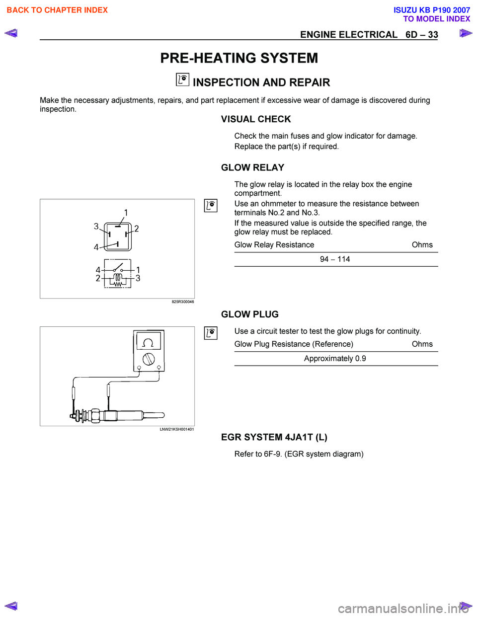
GLOW RELAY
The glow relay is located in the relay box the engine
compartment.
825R300046
Use an ohmmeter to measure the resistance between
terminals No.2 and No.3.
If the measured value is outside the specified range, the
glow relay must be replaced.
Glow Relay Resistance Ohms
94 − 114
GLOW PLUG
LNW21KSH001401
Use a circuit tester to test the glow plugs for continuity.
Glow Plug Resistance (Reference) Ohms
Approximately 0.9
EGR SYSTEM 4JA1T (L)
Refer to 6F-9. (EGR system diagram)
BACK TO CHAPTER INDEX
TO MODEL INDEX
ISUZU KB P190 2007
Page 1056 of 6020

6E-22 Engine Control System (4JH1)
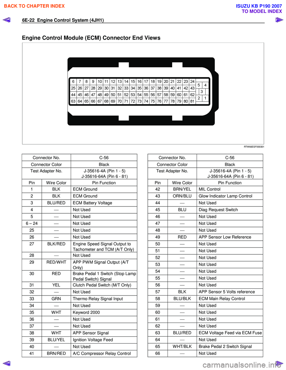
Engine Control Module (ECM) Connector End Views
RTW 66ESF000301
Connector No. C-56
Connector Color Black
Test Adapter No. J-35616-4A (Pin 1 - 5)
J-35616-64A (Pin 6 - 81)
Pin W ire Color Pin Function
1 BLK ECM Ground
2 BLK ECM Ground
3 BLU/RED ECM Battery Voltage
4 Not Used
5 Not Used
6 – 24 Not Used
25 Not Used
26 Not Used
27 BLK/RED Engine Speed Signal Output to
Tachometer and TCM (A/T Only)
28 Not Used
29 RED/W HT APP PW M Signal Output (A/T
Only)
30 RED Brake Pedal 1 Switch (Stop Lamp Pedal Switch) Signal
31 YEL Clutch Pedal Switch (M/T Only)
32 Not Used
33 GRN Thermo Relay Signal Input
34 Not Used
35 W HT Keyword 2000
36 Not Used
37 Not Used
38 W HT APP Sensor Signal
39 BLU/YEL Ignition Voltage Feed
40 Not Used
41 BRN/RED A/C Compressor Relay Control
Connector No. C-56
Connector Color Black
Test Adapter No. J-35616-4A (Pin 1 - 5)
J-35616-64A (Pin 6 - 81)
Pin W ire Color Pin Function
42 BRN/YEL MIL Control
43 ORN/BLU Glow Indicator Lamp Control
44 Not Used
45 BLU Diag Request Switch
46 Not Used
47 Not Used
48 Not Used
49 RED APP Sensor Low Reference
50 Not Used
51 Not Used
52 Not Used
53 Not Used
54 Not Used
55 Not Used
56 Not Used
57 BLK APP Sensor 5 Volts reference
58 BLU/BLK ECM Main Relay Control
59 Not Used
60 Not Used
61 Not Used
62 Not Used
63 BLU/RED ECM Voltage Feed via ECM Fuse
64 Not Used
65 W HT/BLK Brake Pedal 2 Switch Signal
66 Not Used
BACK TO CHAPTER INDEX
TO MODEL INDEX
ISUZU KB P190 2007
Page 1071 of 6020

Engine Control System (4JH1) 6E-37
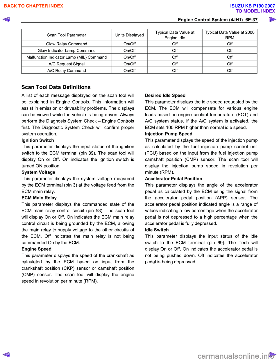
Scan Tool Parameter Units DisplayedTypical Data Value at
Engine Idle
Typical Data Value at 2000
RPM
Glow Relay Command On/Off Off Off
Glow Indicator Lamp Command On/Off Off Off
Malfunction Indicator Lamp (MIL) Command On/Off Off Off
A/C Request Signal On/Off Off Off
A/C Relay Command On/Off Off Off
Scan Tool Data Definitions
A list of each message displayed on the scan tool will
be explained in Engine Controls. This information will
assist in emission or driveability problems. The displays
can be viewed while the vehicle is being driven. Always
perform the Diagnosis System Check – Engine Controls
first. The Diagnostic System Check will confirm prope
r
system operation.
Ignition Switch
This parameter displays the input status of the ignition
switch to the ECM terminal (pin 39). The scan tool will
display On or Off. On indicates the ignition switch is
turned ON position.
System Voltage
This parameter displays the system voltage measured
by the ECM terminal (pin 3) at the voltage feed from the
ECM main relay.
ECM Main Relay
This parameter displays the commanded state of the
ECM main relay control circuit (pin 58). The scan tool
will display On or Off. On indicates the ECM main rela
y
control circuit is being grounded by the ECM, allowing
the main relay to supply voltage to the other circuits o
f
the ECM. Off indicates the main relay is not being
commanded On by the ECM.
Engine Speed
This parameter displays the speed of the crankshaft as
calculated by the ECM based on input from the
crankshaft position (CKP) sensor or camshaft position
(CMP) sensor. The scan tool will display the engine
speed in revolution per minute (RPM).
Desired Idle Speed
This parameter displays the idle speed requested by the
ECM. The ECM will compensate for various engine
loads based on engine coolant temperature (ECT) and
A/C system status. If the A/C system is activated, the
ECM sets 100 RPM higher than normal idle speed.
Injection Pump Speed
This parameter displays the speed of the injection pump
as calculated by the fuel injection pump control unit
(PCU) based on the input from the fuel injection pump
camshaft position (CMP) sensor. The scan tool will
display the injection pump speed in revolution pe
r
minute (RPM).
Accelerator Pedal Position
This parameter displays the angle of the accelerato
r
pedal as calculated by the ECM using the signal from
the accelerator pedal position (APP) sensor. The
accelerator pedal position indicated angle is a range o
f
values indicating a low percentage when the accelerator
pedal is not depressed to a high percentage when the
accelerator pedal is fully depressed.
Idle Switch
This parameter displays the input status of the idle
switch to the ECM terminal (pin 69). The Tech will
display On or Off. On indicates the accelerator pedal is
not being pushed down. Off indicates the accelerato
r
pedal is being depressed.
BACK TO CHAPTER INDEX
TO MODEL INDEX
ISUZU KB P190 2007