2007 ISUZU KB P190 fuse
[x] Cancel search: fusePage 1084 of 6020

6E-50 Engine Control System (4JH1)
Diagnostic Trouble Code (DTC) List
DTC
(Symptom Code) Flash
Code MIL
Status DTC Name on
scan tool Condition for
Running the DTC Condition for
Setting the DTC Possible Cause
P0100
(7) 65 ON Mass Air Flow
(MAF) Sensor
Circuit 5V
Reference High
Voltage •
The ignition switch
is ON.
•
The ECM detects
that the MAF sensor
5 volts reference
circuit voltage is
more than 5.2 volts
for 0.5 seconds. •
Sensor 5V reference circuit is
short to battery or ignition
voltage.
• Sensor 5V reference circuit is
short to the sensor ignition
voltage circuit.
• Faulty MAF sensor.
• Faulty ECM.
P0100 (9) 65 ON Mass Air Flow
(MAF) Sensor
Voltage 5V
Reference Circuit
Low Voltage •
The ignition switch
is ON.
•
The ECM detects
that the MAF sensor
5 volts reference
circuit voltage is
less than 4.6 volts
for 0.5 seconds. •
Sensor 5V reference circuit is
short to ground.
• Sensor 5V reference circuit is
short to the low reference circuit.
• Faulty MAF sensor.
• Faulty ECM.
P0100 (B) 65 ON Mass Air Flow
(MAF) Sensor
Circuit Low
Voltage •
The ignition switch
is ON.
• The engine is
running.
•
The ECM calculated
MAF is lower than -
18.6 kg/h for 5
seconds.
•
ECM (10A) fuse (EB1) open.
• Sensor ignition voltage feed
circuit is open circuit or high
resistance.
• Sensor 5V reference circuit is
open circuit, high resistance,
short to ground or short to the
low reference circuit.
• Sensor signal circuit is open
circuit, high resistance, short to
ground or short to the low
reference circuit.
• Poor harness connector
connection.
• Faulty MAF sensor installation.
• Faulty MAF sensor.
• Faulty ECM.
P0100 (C) 65 ON Mass Air Flow
(MAF) Sensor
Circuit High
Voltage •
The ignition switch
is ON.
• The engine is
running.
•
The ECM calculated
MAF is higher than
984 kg/h for 10
seconds.
•
Sensor signal circuit is short to
any 5V reference circuit, short to
battery or ignition voltage circuit.
• Sensor low reference circuit is
open circuit or high resistance.
• Poor harness connector
connection.
• Faulty MAF sensor.
• Faulty ECM.
P0105 (1) 34 ON Vacuum Pressure
Sensor Circuit
High Voltage •
The ignition switch
is ON. •
The ECM detects
that the vacuum
pressure sensor
signal voltage is
more than 4.4 volts
for 3 seconds. •
Sensor 5V reference circuit is
short to battery or ignition
voltage.
• Sensor signal circuit is short to
any 5V reference circuit, short to
battery or ignition voltage.
• Sensor low reference circuit is
open circuit or high resistance.
• Poor harness connector
connection.
• Faulty vacuum pressure sensor.
• Faulty ECM.
BACK TO CHAPTER INDEX
TO MODEL INDEX
ISUZU KB P190 2007
Page 1087 of 6020
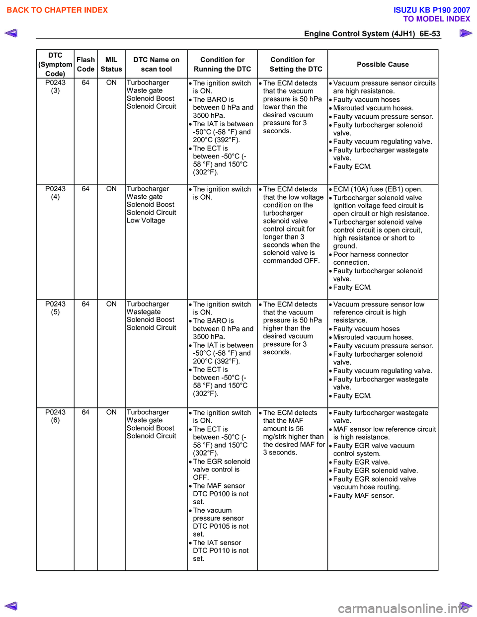
Engine Control System (4JH1) 6E-53
DTC
(Symptom Code) Flash
Code MIL
Status DTC Name on
scan tool Condition for
Running the DTC Condition for
Setting the DTC Possible Cause
P0243
(3) 64 ON Turbocharger
W aste gate
Solenoid Boost
Solenoid Circuit •
The ignition switch
is ON.
• The BARO is
between 0 hPa and
3500 hPa.
• The IAT is between
-50°C (-58 °F) and
200°C (392°F).
• The ECT is
between -50°C (-
58 °F) and 150°C
(302°F).
•
The ECM detects
that the vacuum
pressure is 50 hPa
lower than the
desired vacuum
pressure for 3
seconds.
•
Vacuum pressure sensor circuits
are high resistance.
• Faulty vacuum hoses
• Misrouted vacuum hoses.
• Faulty vacuum pressure sensor.
• Faulty turbocharger solenoid
valve.
• Faulty vacuum regulating valve.
• Faulty turbocharger wastegate
valve.
• Faulty ECM.
P0243 (4) 64 ON Turbocharger
W aste gate
Solenoid Boost
Solenoid Circuit
Low Voltage •
The ignition switch
is ON.
•
The ECM detects
that the low voltage
condition on the
turbocharger
solenoid valve
control circuit for
longer than 3
seconds when the
solenoid valve is
commanded OFF.
•
ECM (10A) fuse (EB1) open.
• Turbocharger solenoid valve
ignition voltage feed circuit is
open circuit or high resistance.
• Turbocharger solenoid valve
control circuit is open circuit,
high resistance or short to
ground.
• Poor harness connector
connection.
• Faulty turbocharger solenoid
valve.
• Faulty ECM.
P0243 (5) 64 ON Turbocharger
W astegate
Solenoid Boost
Solenoid Circuit •
The ignition switch
is ON.
• The BARO is
between 0 hPa and
3500 hPa.
• The IAT is between
-50°C (-58 °F) and
200°C (392°F).
• The ECT is
between -50°C (-
58 °F) and 150°C
(302°F).
•
The ECM detects
that the vacuum
pressure is 50 hPa
higher than the
desired vacuum
pressure for 3
seconds.
•
Vacuum pressure sensor low
reference circuit is high
resistance.
• Faulty vacuum hoses
• Misrouted vacuum hoses.
• Faulty vacuum pressure sensor.
• Faulty turbocharger solenoid
valve.
• Faulty vacuum regulating valve.
• Faulty turbocharger wastegate
valve.
• Faulty ECM.
P0243 (6) 64 ON Turbocharger
W aste gate
Solenoid Boost
Solenoid Circuit •
The ignition switch
is ON.
• The ECT is
between -50°C (-
58 °F) and 150°C
(302°F).
• The EGR solenoid
valve control is
OFF.
• The MAF sensor
DTC P0100 is not
set.
• The vacuum
pressure sensor
DTC P0105 is not
set.
• The IAT sensor
DTC P0110 is not
set.
•
The ECM detects
that the MAF
amount is 56
mg/strk higher than
the desired MAF for
3 seconds.
•
Faulty turbocharger wastegate
valve.
• MAF sensor low reference circuit
is high resistance.
• Faulty EGR valve vacuum
control system.
• Faulty EGR valve.
• Faulty EGR solenoid valve.
• Faulty EGR solenoid valve
vacuum hose routing.
• Faulty MAF sensor.
BACK TO CHAPTER INDEX
TO MODEL INDEX
ISUZU KB P190 2007
Page 1090 of 6020
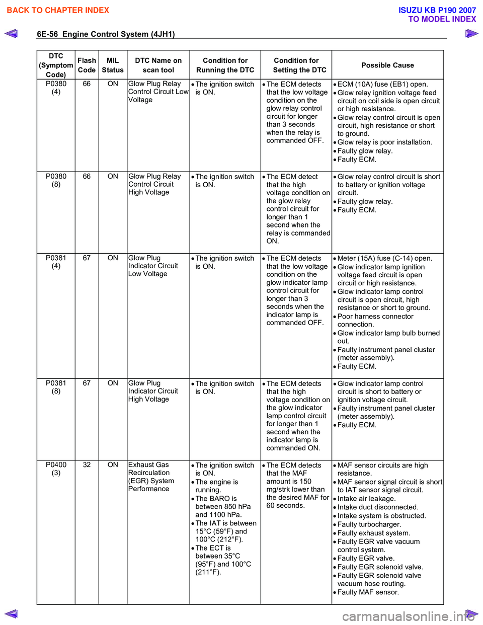
6E-56 Engine Control System (4JH1)
DTC
(Symptom Code) Flash
Code MIL
Status DTC Name on
scan tool Condition for
Running the DTC Condition for
Setting the DTC Possible Cause
P0380
(4) 66 ON Glow Plug Relay
Control Circuit Low
Voltage •
The ignition switch
is ON. •
The ECM detects
that the low voltage
condition on the
glow relay control
circuit for longer
than 3 seconds
when the relay is
commanded OFF.
•
ECM (10A) fuse (EB1) open.
• Glow relay ignition voltage feed
circuit on coil side is open circuit
or high resistance.
• Glow relay control circuit is open
circuit, high resistance or short
to ground.
• Glow relay is poor installation.
• Faulty glow relay.
• Faulty ECM.
P0380 (8) 66 ON
Glow Plug Relay
Control Circuit
High Voltage •
The ignition switch
is ON. •
The ECM detect
that the high
voltage condition on
the glow relay
control circuit for
longer than 1
second when the
relay is commanded
ON.
•
Glow relay control circuit is short
to battery or ignition voltage
circuit.
• Faulty glow relay.
• Faulty ECM.
P0381 (4) 67 ON Glow Plug
Indicator Circuit
Low Voltage •
The ignition switch
is ON.
•
The ECM detects
that the low voltage
condition on the
glow indicator lamp
control circuit for
longer than 3
seconds when the
indicator lamp is
commanded OFF.
•
Meter (15A) fuse (C-14) open.
• Glow indicator lamp ignition
voltage feed circuit is open
circuit or high resistance.
• Glow indicator lamp control
circuit is open circuit, high
resistance or short to ground.
• Poor harness connector
connection.
• Glow indicator lamp bulb burned
out.
• Faulty instrument panel cluster
(meter assembly).
• Faulty ECM.
P0381 (8) 67 ON Glow Plug
Indicator Circuit
High Voltage •
The ignition switch
is ON. •
The ECM detects
that the high
voltage condition on
the glow indicator
lamp control circuit
for longer than 1
second when the
indicator lamp is
commanded ON.
•
Glow indicator lamp control
circuit is short to battery or
ignition voltage circuit.
• Faulty instrument panel cluster
(meter assembly).
• Faulty ECM.
P0400 (3) 32 ON Exhaust Gas
Recirculation
(EGR) System
Performance •
The ignition switch
is ON.
• The engine is
running.
• The BARO is
between 850 hPa
and 1100 hPa.
• The IAT is between
15°C (59°F) and
100°C (212°F).
• The ECT is
between 35°C
(95°F) and 100°C
(211°F).
•
The ECM detects
that the MAF
amount is 150
mg/strk lower than
the desired MAF for
60 seconds.
•
MAF sensor circuits are high
resistance.
• MAF sensor signal circuit is short
to IAT sensor signal circuit.
• Intake air leakage.
• Intake duct disconnected.
• Intake system is obstructed.
• Faulty turbocharger.
• Faulty exhaust system.
• Faulty EGR valve vacuum
control system.
• Faulty EGR valve.
• Faulty EGR solenoid valve.
• Faulty EGR solenoid valve
vacuum hose routing.
• Faulty MAF sensor.
BACK TO CHAPTER INDEX
TO MODEL INDEX
ISUZU KB P190 2007
Page 1091 of 6020
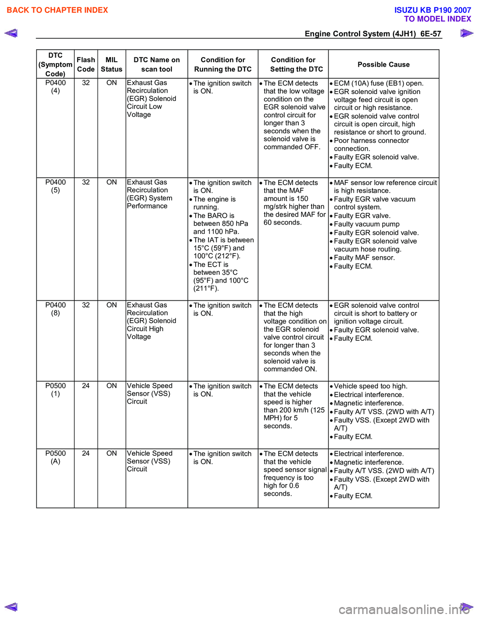
Engine Control System (4JH1) 6E-57
DTC
(Symptom Code) Flash
Code MIL
Status DTC Name on
scan tool Condition for
Running the DTC Condition for
Setting the DTC Possible Cause
P0400
(4) 32 ON Exhaust Gas
Recirculation
(EGR) Solenoid
Circuit Low
Voltage •
The ignition switch
is ON.
•
The ECM detects
that the low voltage
condition on the
EGR solenoid valve
control circuit for
longer than 3
seconds when the
solenoid valve is
commanded OFF.
•
ECM (10A) fuse (EB1) open.
• EGR solenoid valve ignition
voltage feed circuit is open
circuit or high resistance.
• EGR solenoid valve control
circuit is open circuit, high
resistance or short to ground.
• Poor harness connector
connection.
• Faulty EGR solenoid valve.
• Faulty ECM.
P0400 (5) 32 ON Exhaust Gas
Recirculation
(EGR) System
Performance •
The ignition switch
is ON.
• The engine is
running.
• The BARO is
between 850 hPa
and 1100 hPa.
• The IAT is between
15°C (59°F) and
100°C (212°F).
• The ECT is
between 35°C
(95°F) and 100°C
(211°F).
•
The ECM detects
that the MAF
amount is 150
mg/strk higher than
the desired MAF for
60 seconds.
•
MAF sensor low reference circuit
is high resistance.
• Faulty EGR valve vacuum
control system.
• Faulty EGR valve.
• Faulty vacuum pump
• Faulty EGR solenoid valve.
• Faulty EGR solenoid valve
vacuum hose routing.
• Faulty MAF sensor.
• Faulty ECM.
P0400 (8) 32 ON Exhaust Gas
Recirculation
(EGR) Solenoid
Circuit High
Voltage
•
The ignition switch
is ON.
•
The ECM detects
that the high
voltage condition on
the EGR solenoid
valve control circuit
for longer than 3
seconds when the
solenoid valve is
commanded ON.
•
EGR solenoid valve control
circuit is short to battery or
ignition voltage circuit.
• Faulty EGR solenoid valve.
• Faulty ECM.
P0500 (1) 24 ON Vehicle Speed
Sensor (VSS)
Circuit
•
The ignition switch
is ON. •
The ECM detects
that the vehicle
speed is higher
than 200 km/h (125
MPH) for 5
seconds.
•
Vehicle speed too high.
• Electrical interference.
• Magnetic interference.
• Faulty A/T VSS. (2W D with A/T)
• Faulty VSS. (Except 2W D with
A/T)
• Faulty ECM.
P0500 (A) 24 ON Vehicle Speed
Sensor (VSS)
Circuit
•
The ignition switch
is ON. •
The ECM detects
that the vehicle
speed sensor signal
frequency is too
high for 0.6
seconds. •
Electrical interference.
• Magnetic interference.
• Faulty A/T VSS. (2W D with A/T)
• Faulty VSS. (Except 2W D with
A/T)
• Faulty ECM.
BACK TO CHAPTER INDEX
TO MODEL INDEX
ISUZU KB P190 2007
Page 1092 of 6020
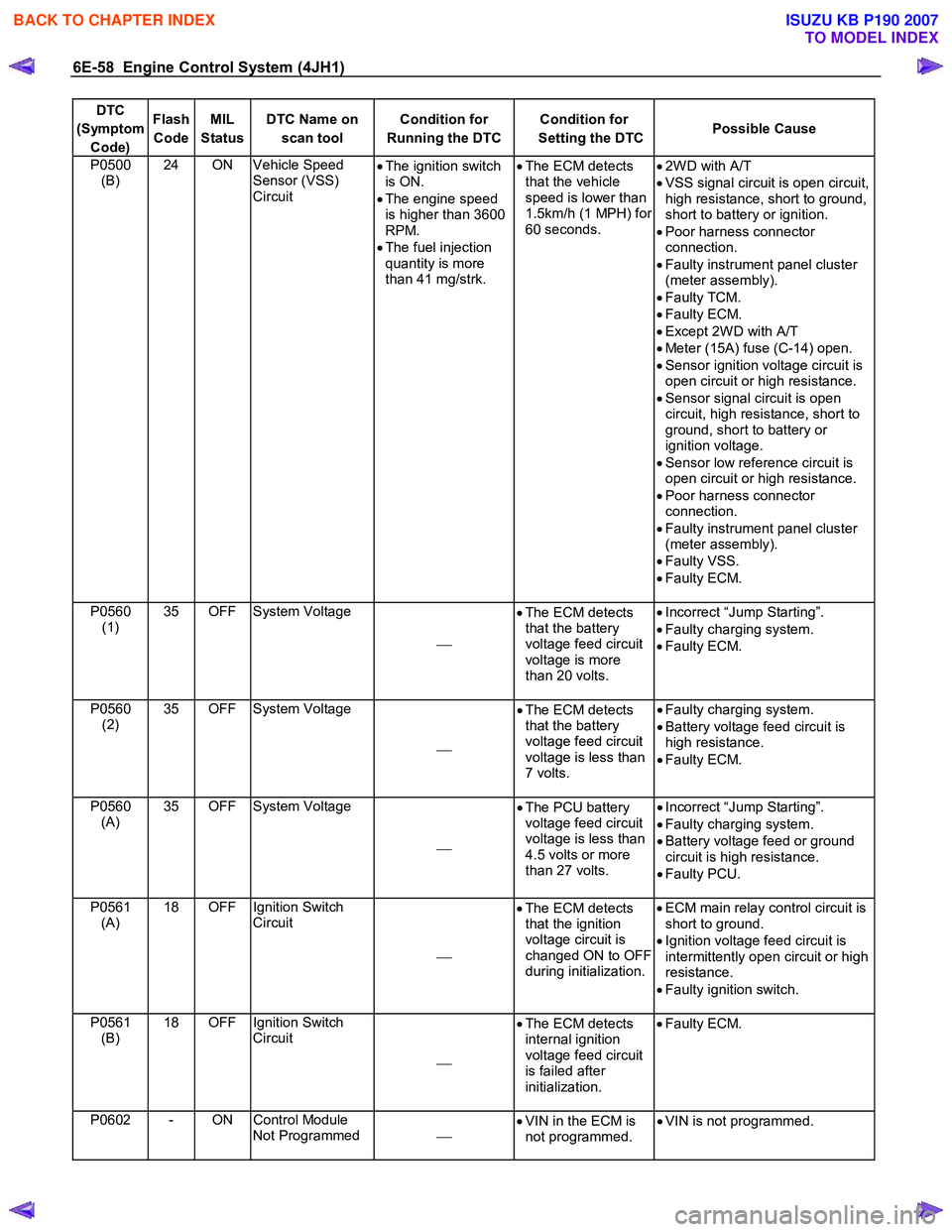
6E-58 Engine Control System (4JH1)
DTC
(Symptom Code) Flash
Code MIL
Status DTC Name on
scan tool Condition for
Running the DTC Condition for
Setting the DTC Possible Cause
P0500
(B) 24 ON Vehicle Speed
Sensor (VSS)
Circuit
•
The ignition switch
is ON.
• The engine speed
is higher than 3600
RPM.
• The fuel injection
quantity is more
than 41 mg/strk.
•
The ECM detects
that the vehicle
speed is lower than
1.5km/h (1 MPH) for
60 seconds.
•
2W D with A/T
• VSS signal circuit is open circuit,
high resistance, short to ground,
short to battery or ignition.
• Poor harness connector
connection.
• Faulty instrument panel cluster
(meter assembly).
• Faulty TCM.
• Faulty ECM.
• Except 2W D with A/T
• Meter (15A) fuse (C-14) open.
• Sensor ignition voltage circuit is
open circuit or high resistance.
• Sensor signal circuit is open
circuit, high resistance, short to
ground, short to battery or
ignition voltage.
• Sensor low reference circuit is
open circuit or high resistance.
• Poor harness connector
connection.
• Faulty instrument panel cluster
(meter assembly).
• Faulty VSS.
• Faulty ECM.
P0560 (1) 35 OFF System Voltage
•
The ECM detects
that the battery
voltage feed circuit
voltage is more
than 20 volts.
•
Incorrect “Jump Starting”.
• Faulty charging system.
• Faulty ECM.
P0560 (2) 35 OFF System Voltage
•
The ECM detects
that the battery
voltage feed circuit
voltage is less than
7 volts.
•
Faulty charging system.
• Battery voltage feed circuit is
high resistance.
• Faulty ECM.
P0560 (A) 35 OFF System Voltage
•
The PCU battery
voltage feed circuit
voltage is less than
4.5 volts or more
than 27 volts.
•
Incorrect “Jump Starting”.
• Faulty charging system.
• Battery voltage feed or ground
circuit is high resistance.
• Faulty PCU.
P0561 (A) 18 OFF Ignition Switch
Circuit
•
The ECM detects
that the ignition
voltage circuit is
changed ON to OFF
during initialization.
•
ECM main relay control circuit is
short to ground.
• Ignition voltage feed circuit is
intermittently open circuit or high
resistance.
• Faulty ignition switch.
P0561 (B) 18 OFF Ignition Switch
Circuit
•
The ECM detects
internal ignition
voltage feed circuit
is failed after
initialization.
•
Faulty ECM.
P0602 - ON Control Module
Not Programmed
•
VIN in the ECM is
not programmed. •
VIN is not programmed.
BACK TO CHAPTER INDEX
TO MODEL INDEX
ISUZU KB P190 2007
Page 1093 of 6020
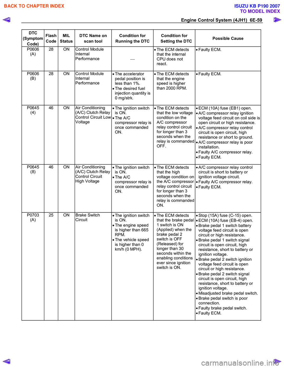
Engine Control System (4JH1) 6E-59
DTC
(Symptom Code) Flash
Code MIL
Status DTC Name on
scan tool Condition for
Running the DTC Condition for
Setting the DTC Possible Cause
P0606
(A) 28 ON Control Module
Internal
Performance
•
The ECM detects
that the internal
CPU does not
react.
•
Faulty ECM.
P0606
(B) 28 ON Control Module
Internal
Performance •
The accelerator
pedal position is
less than 1%.
• The desired fuel
injection quantity is
0 mg/strk.
•
The ECM detects
that the engine
speed is higher
than 2000 RPM. •
Faulty ECM.
P0645
(4) 46 ON Air Conditioning
(A/C) Clutch Relay
Control Circuit Low
Voltage •
The ignition switch
is ON.
• The A/C
compressor relay is
once commanded
ON. •
The ECM detects
that the low voltage
condition on the
A/C compressor
relay control circuit
for longer than 3
seconds when the
relay is commanded
OFF.
•
ECM (10A) fuse (EB1) open.
• A/C compressor relay ignition
voltage feed circuit on coil side is
open circuit or high resistance.
• A/C compressor relay control
circuit is open circuit, high
resistance or short to ground.
• A/C compressor relay is poor
installation.
• Faulty A/C compressor relay.
• Faulty ECM.
P0645 (8) 46 ON Air Conditioning
(A/C) Clutch Relay
Control Circuit
High Voltage •
The ignition switch
is ON.
• The A/C
compressor relay is
once commanded
ON. •
The ECM detects
that the high
voltage condition on
the A/C compressor
relay control circuit
for longer than 3
seconds when the
relay is commanded
ON.
•
A/C compressor relay control
circuit is short to battery or
ignition voltage circuit.
• Faulty A/C compressor relay.
• Faulty ECM.
P0703 (A) 25 ON Brake Switch
Circuit •
The ignition switch
is ON.
• The engine speed
is higher than 665
RPM.
• The vehicle speed
is higher than 0
km/h (0 MPH).
•
The ECM detects
that the brake pedal
1 switch is ON
(Applied) when the
brake pedal 2
switch is OFF
(Released) for
longer than 30
seconds within the
enabling conditions
ever since ignition
switch is ON. •
Stop (15A) fuse (C-15) open.
• ECM (10A) fuse (EB-4) open.
• Brake pedal 1 switch battery
voltage feed circuit is open
circuit or high resistance.
• Brake pedal 1 switch signal
circuit is open circuit, high
resistance, short to battery or
ignition voltage.
• Brake pedal 2 switch ignition
voltage feed circuit is open
circuit or high resistance.
• Brake pedal 2 switch signal
circuit is open circuit, high
resistance, short to battery or
ignition voltage.
• Misadjusted brake pedal switch.
• Brake pedal switch is poor
connection.
• Faulty brake pedal switch.
• Faulty ECM.
BACK TO CHAPTER INDEX
TO MODEL INDEX
ISUZU KB P190 2007
Page 1094 of 6020
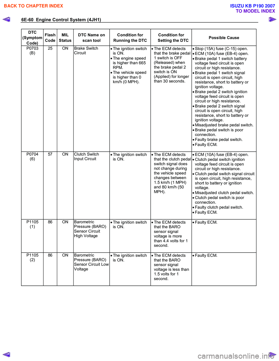
6E-60 Engine Control System (4JH1)
DTC
(Symptom Code) Flash
Code MIL
Status DTC Name on
scan tool Condition for
Running the DTC Condition for
Setting the DTC Possible Cause
P0703
(B) 25 ON Brake Switch
Circuit •
The ignition switch
is ON.
• The engine speed
is higher than 665
RPM.
• The vehicle speed
is higher than 0
km/h (0 MPH).
•
The ECM detects
that the brake pedal
1 switch is OFF
(Released) when
the brake pedal 2
switch is ON
(Applied) for longer
than 30 seconds. •
Stop (15A) fuse (C-15) open.
• ECM (10A) fuse (EB-4) open.
• Brake pedal 1 switch battery
voltage feed circuit is open
circuit or high resistance.
• Brake pedal 1 switch signal
circuit is open circuit, high
resistance, short to battery or
ignition voltage.
• Brake pedal 2 switch ignition
voltage feed circuit is open
circuit or high resistance.
• Brake pedal 2 switch signal
circuit is open circuit, high
resistance, short to battery or
ignition voltage.
• Misadjusted brake pedal switch.
• Brake pedal switch is poor
connection.
• Faulty brake pedal switch.
• Faulty ECM.
P0704 (6) 57 ON Clutch Switch
Input Circuit •
The ignition switch
is ON.
•
The ECM detects
that the clutch pedal
switch signal does
not change during
the vehicle speed
changes between
1.5 km/h (1 MPH)
and 80 km/h (50
MPH).
•
ECM (10A) fuse (EB-4) open.
• Clutch pedal switch ignition
voltage feed circuit is open
circuit or high resistance.
• Clutch pedal switch signal circuit
is open circuit, high resistance,
short to battery or ignition
voltage.
• Misadjusted clutch pedal switch.
• Clutch pedal switch is poor
connection.
• Faulty clutch pedal switch.
• Faulty ECM.
P1105 (1) 86 ON Barometric
Pressure (BARO)
Sensor Circuit
High Voltage
•
The ignition switch
is ON.
•
The ECM detects
that the BARO
sensor signal
voltage is more
than 4.4 volts for 1
second.
•
Faulty ECM.
P1105
(2) 86 ON Barometric
Pressure (BARO)
Sensor Circuit Low
Voltage
•
The ignition switch
is ON.
•
The ECM detects
that the BARO
sensor signal
voltage is less than
1.5 volts for 1
second.
•
Faulty ECM.
BACK TO CHAPTER INDEX
TO MODEL INDEX
ISUZU KB P190 2007
Page 1096 of 6020
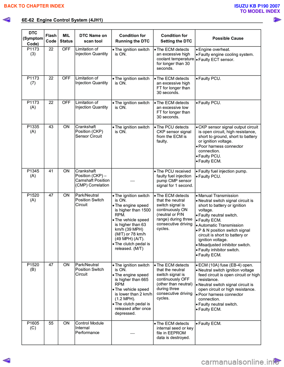
6E-62 Engine Control System (4JH1)
DTC
(Symptom Code) Flash
Code MIL
Status DTC Name on
scan tool Condition for
Running the DTC Condition for
Setting the DTC Possible Cause
P1173
(3) 22 OFF Limitation of
Injection Quantity •
The ignition switch
is ON. •
The ECM detects
an excessive high
coolant temperature
for longer than 30
seconds.
•
Engine overheat.
• Faulty engine cooling system.
• Faulty ECT sensor.
P1173 (7) 22 OFF Limitation of
Injection Quantity
•
The ignition switch
is ON. •
The ECM detects
an excessive high
FT for longer than
30 seconds.
•
Faulty PCU.
P1173 (A) 22 OFF Limitation of
Injection Quantity
•
The ignition switch
is ON. •
The ECM detects
an excessive low
FT for longer than
30 seconds.
•
Faulty PCU.
P1335 (A) 43 ON Crankshaft
Position (CKP)
Sensor Circuit •
The ignition switch
is ON. •
The PCU detects
CKP sensor signal
from the ECM is
faulty.
•
CKP sensor signal output circuit
is open circuit, high resistance,
short to ground, short to battery
or ignition voltage.
• Poor harness connector
connection.
• Faulty PCU.
• Faulty ECM.
P1345 (A) 41 ON Crankshaft
Position (CKP) –
Camshaft Position
(CMP) Correlation
•
The PCU received
faulty fuel injection
pump CMP sensor
signal for 1 second.
•
Faulty fuel injection pump.
• Faulty PCU.
P1520 (A) 47 ON Park/Neutral
Position Switch
Circuit •
The ignition switch
is ON.
• The engine speed
is higher than 1500
RPM.
• The vehicle speed
is higher than 63
km/h (39 MPH)
(M/T) or 78 km/h
(49 MPH) (A/T).
• The clutch pedal is
released. (M/T)
•
The ECM detects
that the neutral
switch signal is
continuously ON
(neutral or P/N
range) during three
consecutive driving
cycles.
•
Manual Transmission
• Neutral switch signal circuit is
short to battery or ignition
voltage.
• Faulty neutral switch.
• Faulty ECM.
• Automatic Transmission
• P & N position switch signal
circuit is short to battery or
ignition voltage.
• Misadjusted inhibitor switch.
• Faulty inhibitor switch.
• Faulty ECM.
P1520 (B) 47 ON Park/Neutral
Position Switch
Circuit •
The ignition switch
is ON.
• The engine speed
is higher than 665
RPM
• The vehicle speed
is lower than 2 km/h
(1.2 MPH).
• The clutch pedal is
released after once
depressed.
•
The ECM detects
that the neutral
switch signal is
continuously OFF
(other than neutral)
during three
consecutive driving
cycles.
•
ECM (10A) fuse (EB-4) open.
• Neutral switch ignition voltage
feed circuit is open circuit or high
resistance.
• Neutral switch signal circuit is
open circuit or high resistance.
• Poor harness connector
connection.
• Faulty neutral switch.
• Faulty ECM.
P1605 (C) 55 ON Control Module
Internal
Performance •
The ECM detects
internal seed or key
file in EEPROM
data is destroyed.
•
Faulty ECM.
BACK TO CHAPTER INDEX
TO MODEL INDEX
ISUZU KB P190 2007