Page 929 of 6020

6A – 124 ENGINE MECHANICAL
20. Power Steering Oil Pump Bracket
Oil Pump Braket Nut and Bolt Torque N·m(kg·m/Ib ft)
1M10 ×1.25
37 (3.8/28)
2
3M8×1.25
18 (1.8/13) (Bolt ID:8)
040R300005
21. Fuel Injection Pipe with Clip
1) Temporarily tighten the injection pipe sleeve nut.
2) Set the clip in the illustrated position. Note:
Make absolutely sure that the clip is correctly
positioned.
An improperly positioned clip will result in injection
pipe breakage and fuel pulsing noise.
3) Tighten the injection pipe sleeve nut to the specified torque.
Torque
Injection Pump Side (4JA1TC/4JH1TC) N·m(kg·m/Ib ft)
40 (4.1/30)
Injection Pipe Sleeve Nuts N·m(kg·m/Ib ft)
29 (3.0/22)
Injection Pipe Clip Nuts N·m(kg·m/Ib ft)
8 (0.8/6)
22. Fuel Filter Bracket (Except EURO III model)
Install the fuel filter bracket and tighten fixing bolts to the
specified torque.
Fuel Filter Bracket Bolt Torque N·m(kg·m/Ib ft)
21 (2.1/15)
23. Fuel Filter Assembly (Except EURO III model)
Install the fuel filter assembly and tighten fixing bolts to the
specified torque.
Fuel Filter Assembly Bolt Torque N·m(kg·m/Ib ft)
21 (2.1/15)
24. Oil Level Gauge
Install the oil level gauge and tighten fixing bolts to the
specified torque.
Oil Level Gauge Bolt Torque N·m(kg·m/Ib ft)
M8 19 (1.9/14)
M6 8 (0.8/6)
431RY00013
BACK TO CHAPTER INDEX
TO MODEL INDEX
ISUZU KB P190 2007
Page 965 of 6020

SECTION 6C
FUEL SYSTEM
TABLE OF CONTENTS
PAGE
Main Data and Specifications ....................................................................................... 6C - 2
General Description ...................................................................................................... 6C - 3
Fuel Flow.................................................................................................................... 6 C - 3
Fuel Filter and Water Separator ............................................................................... 6C - 4
Injection Pump........................................................................................................... 6C - 6
Injection Nozzle ......................................................................................................... 6C - 7
Fuel Tank...................................................................................................................... .. 6C - 8
Removal .................................................................................................................... 6 C - 9
Installation ................................................................................................................ 6C - 9
Fuel Gauge Unit ............................................................................................................. 6C - 11
Removal ..................................................................................................................... 6 C - 12
Installation ................................................................................................................. 6C - 12
Fuel Tube / Quick - Connector Fittings........................................................................ 6C - 14
Filler Neck .................................................................................................................... .. 6C - 16
Removal ..................................................................................................................... 6 C - 16
Installation ................................................................................................................. 6C - 16
Fuel Filler Cap................................................................................................................ 6C - 17
Injection Pump ............................................................................................................... 6 C - 18
Removal and Installation .......................................................................................... 6C - 18
Removal ..................................................................................................................... 6C - 18
Installation ................................................................................................................. 6 C - 21
Injection Nozzle (4JA1L) ............................................................................................... 6C - 25
Disassembly .............................................................................................................. 6C - 25
Reassembly ............................................................................................................... 6C - 26
Special tools .................................................................................................................. 6C - 37
FU
EL SY STEM 6C – 1
BACK TO CHAPTER INDEX
TO MODEL INDEX
ISUZU KB P190 2007
Page 966 of 6020

6C – 2 FUEL SYSTEM
MAIN DATA AND SPECIFICATIONS
Description Item
4JA1T (L) 4JA1TC 4JH1TC
Injection pump type Bosch distributor
VE type Bosch distributor VP44 type
Governor type
Mechanical variable
(Half speed oil pressure) Electrical controled
Timer type
Oil pressure Electrical controled
Fuel feed pump type Vane with input shaft
Injection nozzle type Hole type
Number of injection nozzle orifices 5
Injection nozzle orifices
Inside diameter mm (in) 0.19 (0.0075) 0.17 (0.0067) 0.21 (0.0083)
19.1 (195) 19.0 (194) 19.5 (199) Injection nozzle designed operating
pressure MPa (kg/cm2) 1st
2nd 25.0 (255)
33.5 (328) 33.8 (331)
Main fuel filter type Disposable cartridge paper element
Precautions
When working on the fuel system, there are several things
to keep in mind:
•
Any time the fuel system is being worked on,
disconnect the negative battery cable except fo
r
those tests where battery voltage is required.
•
Always keep a dry chemical (Class B) fire
extinguisher near the work area.
• Replace all pipes with the same pipe and fittings that
were removed.
• Clean and inspect “O” rings. Replace if required.
•
Always relieve the line pressure before servicing any
fuel system components.
• Do not attempt repairs on the fuel system until you
have read the instructions and checked the pictures
relating to that repair.
• Adhere to all Notices and Cautions.
NOTE:
Injection nozzle adjustment is possible only on the 4JA1L
engine.
BACK TO CHAPTER INDEX
TO MODEL INDEX
ISUZU KB P190 2007
Page 967 of 6020
FUEL SYSTEM 6C – 3
GENERAL DESCRIPTION
FUEL FLOW
RTW 66CMF000101
The fuel system consists of the fuel tank, the fuel filter, the water separator, the injection pump, and the injection
nozzle.
The fuel from the fuel tank passes through the water separator and the fuel filter where water particles and other
foreign material are removed from the fuel.
Fuel, fed by the injection pump plunger, is delivered to the injection nozzle in the measured volume at the optimum
timing for efficient engine operation.
NOTE:
1 If it find abnormal condition on the fuel injector, refer to section 6E ENGINE DRIVEABILITY AND EMISSIONS.
2 Do not contain "Additive for water drain" with fuel.
BACK TO CHAPTER INDEX
TO MODEL INDEX
ISUZU KB P190 2007
Page 968 of 6020
6C – 4 FUEL SYSTEM
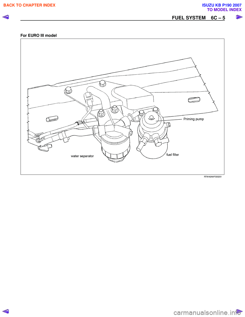
FUEL FILTER AND WATER SEPARATOR
As the inside of the injection pump is lubricated by the fuel which it is pumping, the fuel must be perfectly clean. The
fuel filter and the water separator remove water particles and other foreign material from the fuel before it reaches
the injection pump.
The water separator has an internal float. W hen the float reaches the specified level, a warning light comes on to
remind you to drain the water from the water separator.
A diaphragm type priming pump is installed at the top of the fuel filter. It is used during the air bleeding procedures.
(Except EURO III model)
RTW 36CLF000701
BACK TO CHAPTER INDEX
TO MODEL INDEX
ISUZU KB P190 2007
Page 969 of 6020
FUEL SYSTEM 6C – 5
For EURO III model
RTW 46AMF000201
BACK TO CHAPTER INDEX
TO MODEL INDEX
ISUZU KB P190 2007
Page 970 of 6020

6C – 6 FUEL SYSTEM
INJECTION PUMP
RTW 46CLF000201
4JA1T(L):
A Bosch Distributor Type Injection Pump is used. A single reciprocating/revolving plunger delivers the fuel uniformly
to the injection nozzles, regardless of the number of cylinders.
The governor, the injection timer, and the feed pump are all contained in the injection pump housing. The injection
pump is compact, light weight, and provides reliable high-speed operation.
The vacuum-type fast idle actuator increases the engine idling speed to provide the additional power required to
operate the air conditioner.
Fast idler diaphragm movement is caused by changes in the negative pressure created by the engine’s vacuum
pump.
The diaphragm motion is transferred to the injection pump control lever to increase or decrease the idling speed.
4JA1TC/4JH1TC:
The Bosch VP44 injection pump is electronically controlled. The pump controller combine to injection pump.
Signals from the pump controller are sent to the engine control module (ECM). In response to these signals, the
ECM selects the optimum fuel injection timing and volume for the existing driving conditions.
BACK TO CHAPTER INDEX
TO MODEL INDEX
ISUZU KB P190 2007
Page 971 of 6020
FUEL SYSTEM 6C – 7
INJECTION NOZZLE (4JA1L)
RTW 76CMF000301
NOTE:
• Injection nozzle adjustment is possible only on the 4JA1L engine.
A hole (with 5 orifices) type injection nozzle. It consists of the nozzle body and the needle valve assembly.
The injection nozzle assembly sprays pressurized fuel from the injection pump into the combustion chamber through
the nozzle body injection orifice.
BACK TO CHAPTER INDEX
TO MODEL INDEX
ISUZU KB P190 2007