Page 10 of 6020
0A-8 GENERAL INFORMATION
RUW 50ASH000101
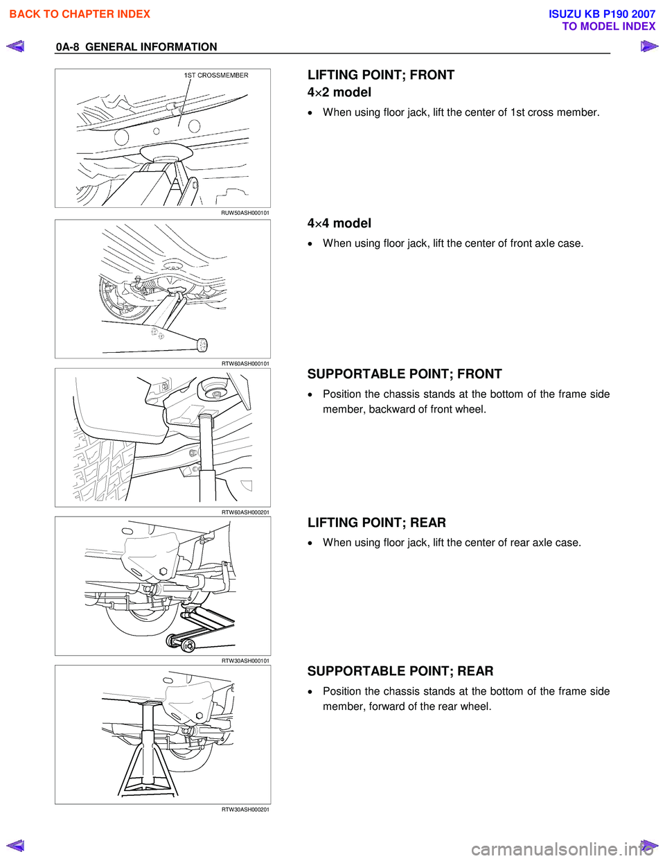
LIFTING POINT; FRONT
4 ×
××
×
2 model
• W hen using floor jack, lift the center of 1st cross member.
RTW 60ASH000101
4 ×
××
×
4 model
• W hen using floor jack, lift the center of front axle case.
RTW 60ASH000201
SUPPORTABLE POINT; FRONT
• Position the chassis stands at the bottom of the frame side
member, backward of front wheel.
RTW 30ASH000101
LIFTING POINT; REAR
• W hen using floor jack, lift the center of rear axle case.
RTW 30ASH000201
SUPPORTABLE POINT; REAR
• Position the chassis stands at the bottom of the frame side
member, forward of the rear wheel.
BACK TO CHAPTER INDEX
TO MODEL INDEX
ISUZU KB P190 2007
Page 250 of 6020

3A-2 FRONT ALIGNMENT
Front End Alignment Inspection and
Adjustment
General Description
“Front End Alignment” refers to the angular relationship
between the front wheels, the front suspension attaching parts
and the ground.
Proper front end alignment must be maintained in order to
insure efficient steering, good directional stability and to
prevent abnormal tire wear.
The most important factors of front end alignment are wheel
toe-in, wheel camber and axle caster.
Camber:
This illustration shows a view from the front of the vehicle.
Camber is the vertical tilting inward or outward of the front
wheels. W hen the wheels tilt outward at the top, the camber is
positive (+). W hen the wheels tilt inward at the top, the camber
is negative (-). The amount of tilt measured in degrees from
the vertical is called the camber angle (1). If camber is extreme
or unequal between the wheels, improper steering and
excessive tire wear will result. Negative camber causes wear
on the inside of the tire, while positive camber causes wear to
the outside.
Caster:
This illustration shows a view from the side of the vehicle.
Caster (1) is the vertical tilting of the wheel axis either
forward or backward (when viewed from the side of the
vehicle). A backward tilt is positive (+) and a forward tilt is
negative (-). On the short and long arm type suspension
you cannot see a caster angle without a special instrument, but
if you look straight down from the top of the upper control arm
to the ground, the ball joints do not line up (fore and aft) when
a caster angle other than 0 degrees is present. W ith a positive
angle, the lower ball joint would be slightly ahead (toward the
front of the vehicle) of the upper ball joint center line.
Toe-in:
This illustration shows a view from the top of the vehicle.
Toe-in is the measured amount the front wheels are turned in.
The actual amount of toe-in is normally a fraction of a degree.
Toe-in is measured from the center of the tire treads or from
the inside of the tires. The purpose of toe-in is to insure parallel
rolling of the front wheels and to offset any small deflections of
the wheel support system which occurs when the vehicle is
rolling forward. Incorrect toe-in results in excessive toe-in and
unstable steering. Toe-in is the last alignment to be set in
the front end alignment procedure.
BACK TO CHAPTER INDEX
TO MODEL INDEX
ISUZU KB P190 2007
Page 428 of 6020

4A-12 PROPELLER SHAFT
Removal and Installation
401RS023
Removal
1. Raise the vehicle on a hoist.
NOTE:
Apply alignment marks on the flange at the rear
propeller shaft both front and rear side.
2. Remove center bearing fixing bolt.
3. Remove rear axle side bolt, nut and washer.
4. Remove rear propeller shaft.
NOTE:
Plug the hole of the transmission rear end to prevent oil
leakage.
401L100007
Installation
NOTE:
Cover the slip yoke with cloth to avoid damage to the oil seal
contact surface, when removing propeller shaft from
transmission. Do not damage the oil seal contact surface of
slip yoke with other parts at removal and installation.
Completely remove the dust or foreign matter from the
connecting surface of flange coupling on each end of the
propeller shaft.
1.
Align the mark which is applied at removal and insert the
propeller shaft in the transmission.
2. Install rear propeller shaft and tighten the bolts to the specified torque.
Torque: 59 N ⋅
⋅⋅
⋅
m (6.0 kgf ⋅
⋅⋅
⋅
m/43 lb ⋅
⋅⋅
⋅
ft)
3. Install center bearing and tighten the bolts to the specified torque.
Torque: 69 N ⋅
⋅⋅
⋅
m (7.0 kgf ⋅
⋅⋅
⋅
m/51 lb ⋅
⋅⋅
⋅
ft)
BACK TO CHAPTER INDEX
TO MODEL INDEX
ISUZU KB P190 2007
Page 520 of 6020

4C1-16 FRONT WHEEL DRIVE
6. Using snap ring pliers, remove the snap ring (1) fastening
the ball retainer to the center shaft.
7. Remove ball retainer, ball guide and bellows.
8. Use a hammer and chisel to remove the 3 pawls (above
the large and small boot bands on the UJ side).
CAUTION :
Take care not to damage the bellows during band removal.
9. Remove band (1).
10. Remove bellows.
11. Remove dust seal from UJ.
12. Remove UJ shaft assembly.
13. Remove the mounting bracket fixing bolts, and then remove DOJ case assembly from the axle case.
14. Remove snap ring and bearing.
15. Remove snap ring and oil seal.
16. Remove bracket.
Inspection and Repair
Make necessary correction or parts replacement if wear,
damage, corrosion or any other abnormal condition are found
through inspection.
Check the following parts.
1. Drive shaft joint assembly
2. DOJ case, ball, ball guide, ball retainer
3. Bellows
4. Bearing
5. Dust seal, oil seal
BACK TO CHAPTER INDEX
TO MODEL INDEX
ISUZU KB P190 2007
Page 4833 of 6020
TRANSFER CASE 7D-3
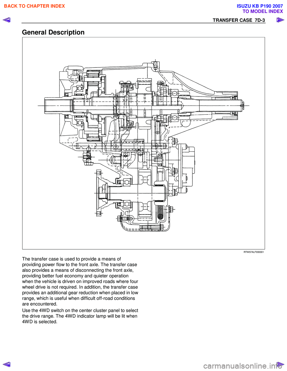
General Description
RTW 57ALF000301
The transfer case is used to provide a means of
providing power flow to the front axle. The transfer case
also provides a means of disconnecting the front axle,
providing better fuel economy and quieter operation
when the vehicle is driven on improved roads where fou
r
wheel drive is not required. In addition, the transfer case
provides an additional gear reduction when placed in lo
w
range, which is useful when difficult off-road conditions
are encountered.
Use the 4W D switch on the center cluster panel to select
the drive range. The 4W D indicator lamp will be lit when
4W D is selected.
BACK TO CHAPTER INDEX
TO MODEL INDEX
ISUZU KB P190 2007