2007 ISUZU KB P190 Engine
[x] Cancel search: EnginePage 5787 of 6020
CAB 10-29
Important Operations
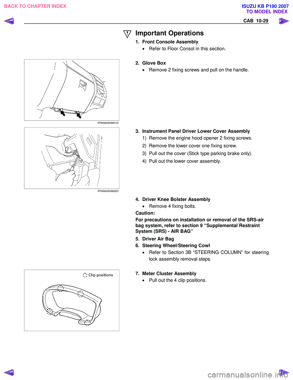
1. Front Console Assembly • Refer to Floor Consol in this section.
RTW 6A0SH000101
2. Glove Box
• Remove 2 fixing screws and pull on the handle.
RTW 6A0SH000201
3. Instrument Panel Driver Lower Cover Assembly
1) Remove the engine hood opener 2 fixing screws.
2) Remove the lower cover one fixing screw.
3) Pull out the cover (Stick type parking brake only).
4) Pull out the lower cover assembly.
4. Driver Knee Bolster Assembly
• Remove 4 fixing bolts.
Caution:
For precautions on installation or removal of the SRS-air
bag system, refer to section 9 “Supplemental Restraint
System (SRS) - AIR BAG”
5. Driver Air Bag
6. Steering Wheel/Steering Cowl • Refer to Section 3B “STEERING COLUMN” for steering
lock assembly removal steps.
7. Meter Cluster Assembly
• Pull out the 4 clip positions.
BACK TO CHAPTER INDEX TO MODEL INDEX
ISUZU KB P190 2007
Page 5857 of 6020
11A-6 IMMOBILIZER CONTROL SYSTEM (4JK1/4JJ1/HFV6)
Component Locator
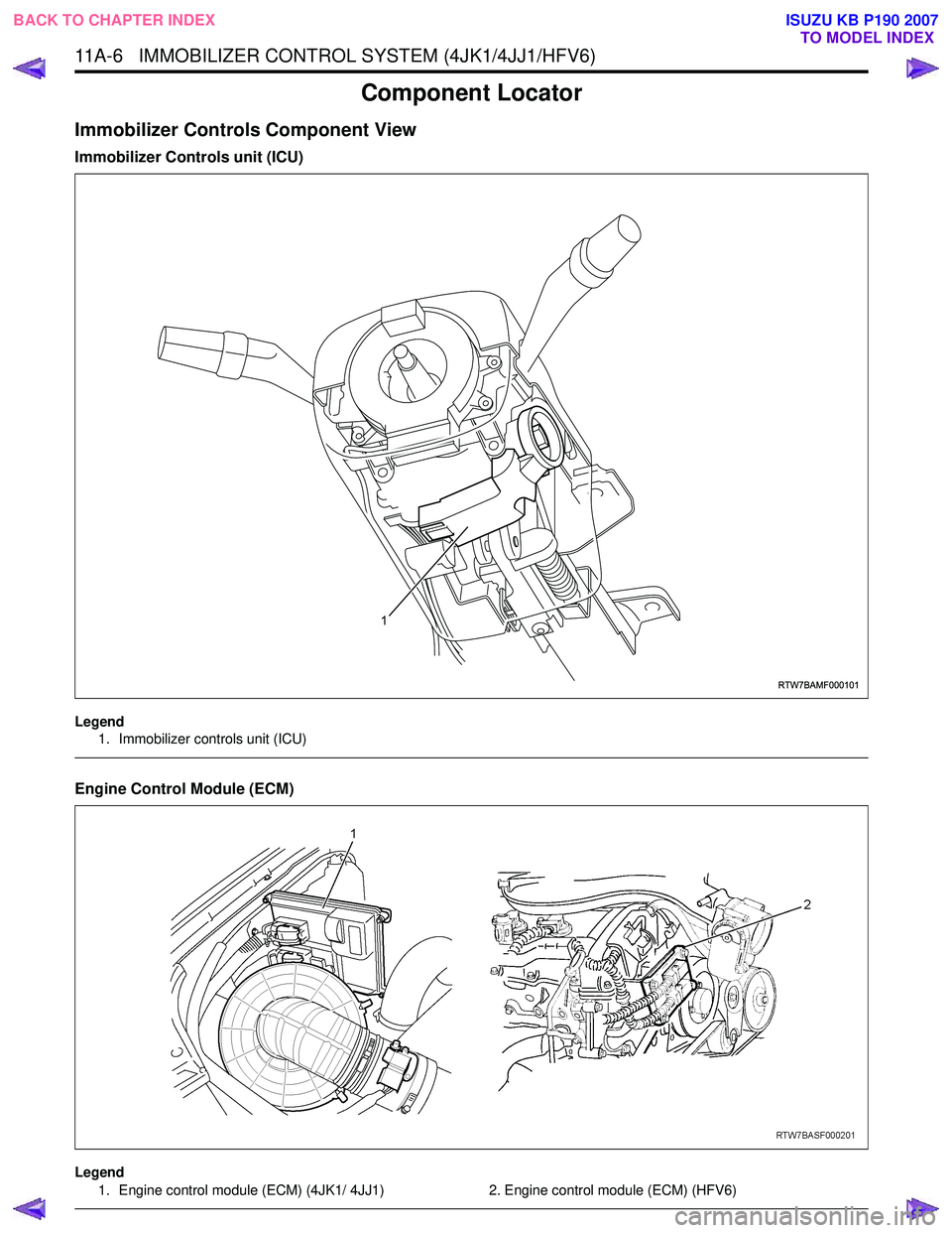
Immobilizer Controls Component View
Immobilizer Controls unit (ICU)
Legend1. Immobilizer controls unit (ICU)
Engine Control Module (ECM)
Legend
1. Engine control module (ECM) (4JK1/ 4JJ1) 2. Engine control module (ECM) (HFV6)
RTW7BAMF000101
1
BACK TO CHAPTER INDEX TO MODEL INDEX
ISUZU KB P190 2007
Page 5859 of 6020
11A-8 IMMOBILIZER CONTROL SYSTEM (4JK1/4JJ1/HFV6)
Diagnostic Information and Procedures
Diagnostic Starting Point - Immobilizer
Controls
Begin the system diagnosis with Diagnostic System
Check - Immobilizer Controls. The Diagnostic System
Check - Immobilizer Controls will provide the following
information:
• The identification of the control modules which command the system.
• The ability of the control modules to communicate through the serial data circuit.
• The identification of any stored diagnostic trouble codes (DTCs) and the their statuses.
The use of the Diagnostic System Check - Immobilizer
Controls will identify the correct procedure for
diagnosing the system and where the procedure is
located.
Diagnostic System Check - Immobilizer
Controls
Description
The Diagnostic System Check - Immobilizer Controls is
an organized approach to identifying a condition that is
created by a malfunction in the electronic immobilizer
control system. The Diagnostic System Check must be
the starting point for any immobilizer system concern.
The Diagnostic System Check directs the service
technician to the next logical step in order to diagnose
the concern. Understanding and correctly using the
diagnostic table reduces diagnostic time, and prevents
the replacement of good parts. Test Description
The numbers below refer to the step numbers on the
diagnostic table.
2. Lack of communication may be because of a partial
or a total malfunction of the serial data circuit.
6. The presence of DTCs which begin with U, indicate
that some other module is not communicating.
9. If there are other modules with DTCs set, refer to the
DTC list. The DTC list directs you to the appropriate
diagnostic procedure.
Important: • DO NOT perform this diagnostic if there is not an immobilizer system concern, unless another
procedure directs you to this diagnostic.
• Before you proceed with diagnosis, search for applicable service bulletins.
• Unless a diagnostic procedure instructs you, DO NOT clear the DTCs.
• Ensure the battery has a full charge.
• Ensure the battery cables (+) (-) are clean and tight.
• Ensure the ICU ground is clean, tight, and in the correct location.
• Ensure the ICU harness connector is clean and correctly connected.
• Ensure the ICU terminals are clean and correctly mating.
• Ensure the immobilizer security information is correctly programmed into the ICU, ECM and PIM.
• Ensure the ICU is correctly installed to the steering lock.
• Ensure objects does not block transponder key in the steering lock.
• Ensure another transponder key is not attached to the key ring.
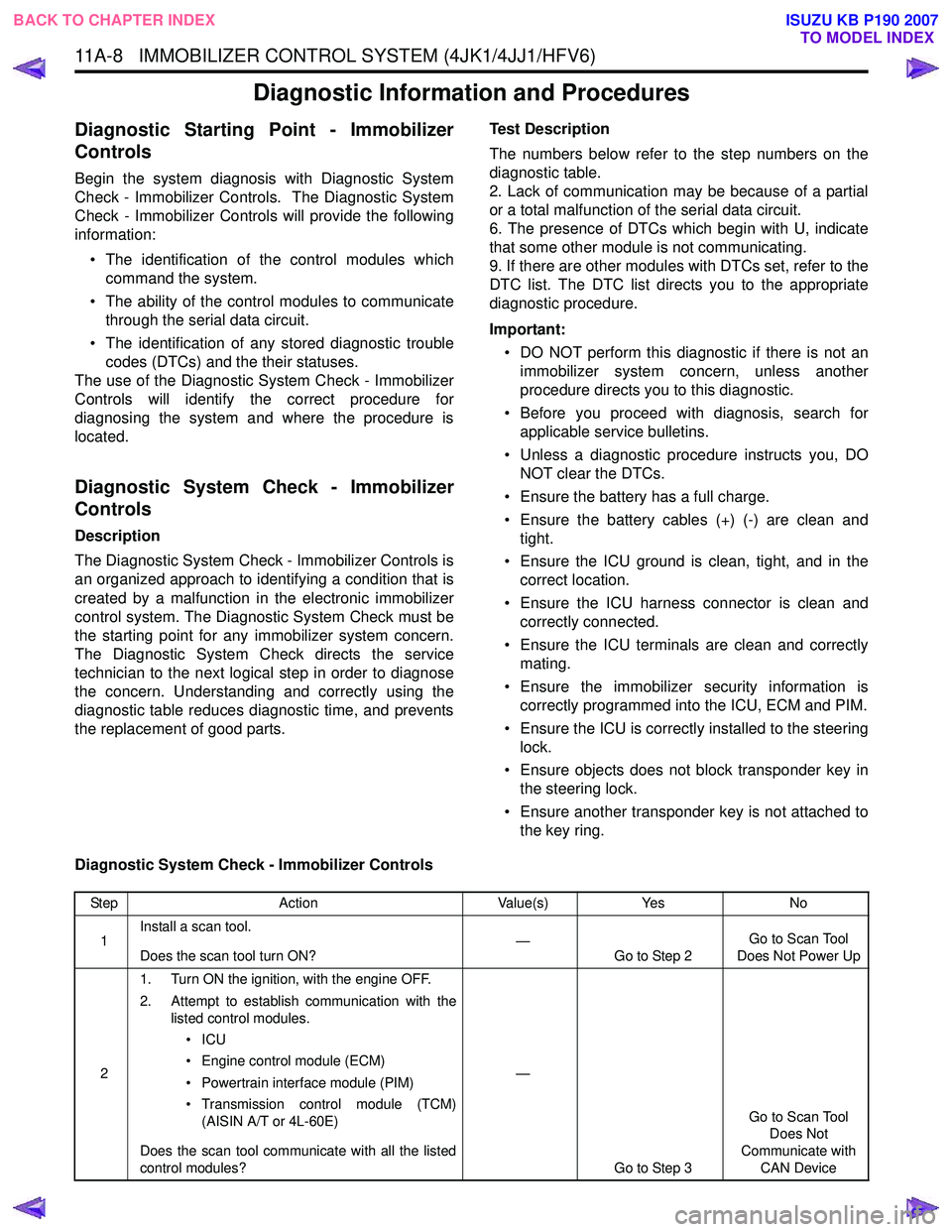
Diagnostic System Check - Immobilizer Controls
Step Action Value(s)Yes No
1 Install a scan tool.
Does the scan tool turn ON? —
Go to Step 2 Go to Scan Tool
Does Not Power Up
2 1. Turn ON the ignition, with the engine OFF.
2. Attempt to establish communication with the listed control modules.
•ICU
• Engine control module (ECM)
• Powertrain interface module (PIM)
• Transmission control module (TCM) (AISIN A/T or 4L-60E)
Does the scan tool communicate with all the listed
control modules? —
Go to Step 3 Go to Scan Tool
Does Not
Communicate with CAN Device
BACK TO CHAPTER INDEX TO MODEL INDEX
ISUZU KB P190 2007
Page 5860 of 6020
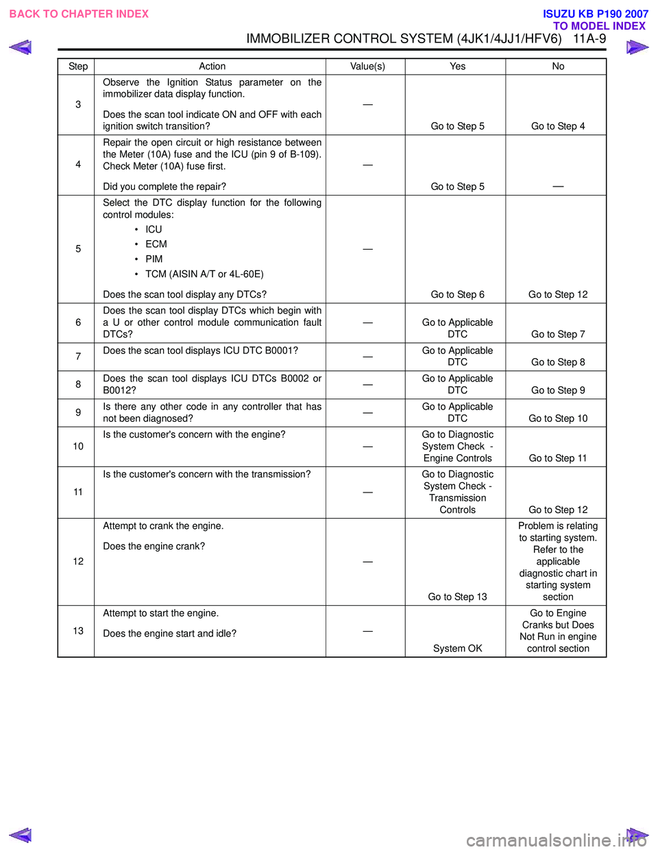
IMMOBILIZER CONTROL SYSTEM (4JK1/4JJ1/HFV6) 11A-9
3Observe the Ignition Status parameter on the
immobilizer data display function.
Does the scan tool indicate ON and OFF with each
ignition switch transition? —
Go to Step 5 Go to Step 4
4 Repair the open circuit or high resistance between
the Meter (10A) fuse and the ICU (pin 9 of B-109).
Check Meter (10A) fuse first.
Did you complete the repair? —
Go to Step 5
—
5Select the DTC display function for the following
control modules:
•ICU
•ECM
•PIM
• TCM (AISIN A/T or 4L-60E)
Does the scan tool display any DTCs? —
Go to Step 6 Go to Step 12
6 Does the scan tool display DTCs which begin with
a U or other control module communication fault
DTCs? —
Go to Applicable
DTC Go to Step 7
7 Does the scan tool displays ICU DTC B0001?
—Go to Applicable
DTC Go to Step 8
8 Does the scan tool displays ICU DTCs B0002 or
B0012? —Go to Applicable
DTC Go to Step 9
9 Is there any other code in any controller that has
not been diagnosed? —Go to Applicable
DTC Go to Step 10
10 Is the customer's concern with the engine?
—Go to Diagnostic
System Check -
Engine Controls Go to Step 11
11 Is the customer's concern with the transmission?
—Go to Diagnostic
System Check - Transmission
Controls Go to Step 12
12 Attempt to crank the engine.
Does the engine crank? —
Go to Step 13 Problem is relating
to starting system. Refer to the
applicable
diagnostic chart in starting system
section
13 Attempt to start the engine.
Does the engine start and idle? —
System OK Go to Engine
Cranks but Does
Not Run in engine
control section
Step
Action Value(s)Yes No
BACK TO CHAPTER INDEX
TO MODEL INDEX
ISUZU KB P190 2007
Page 5864 of 6020
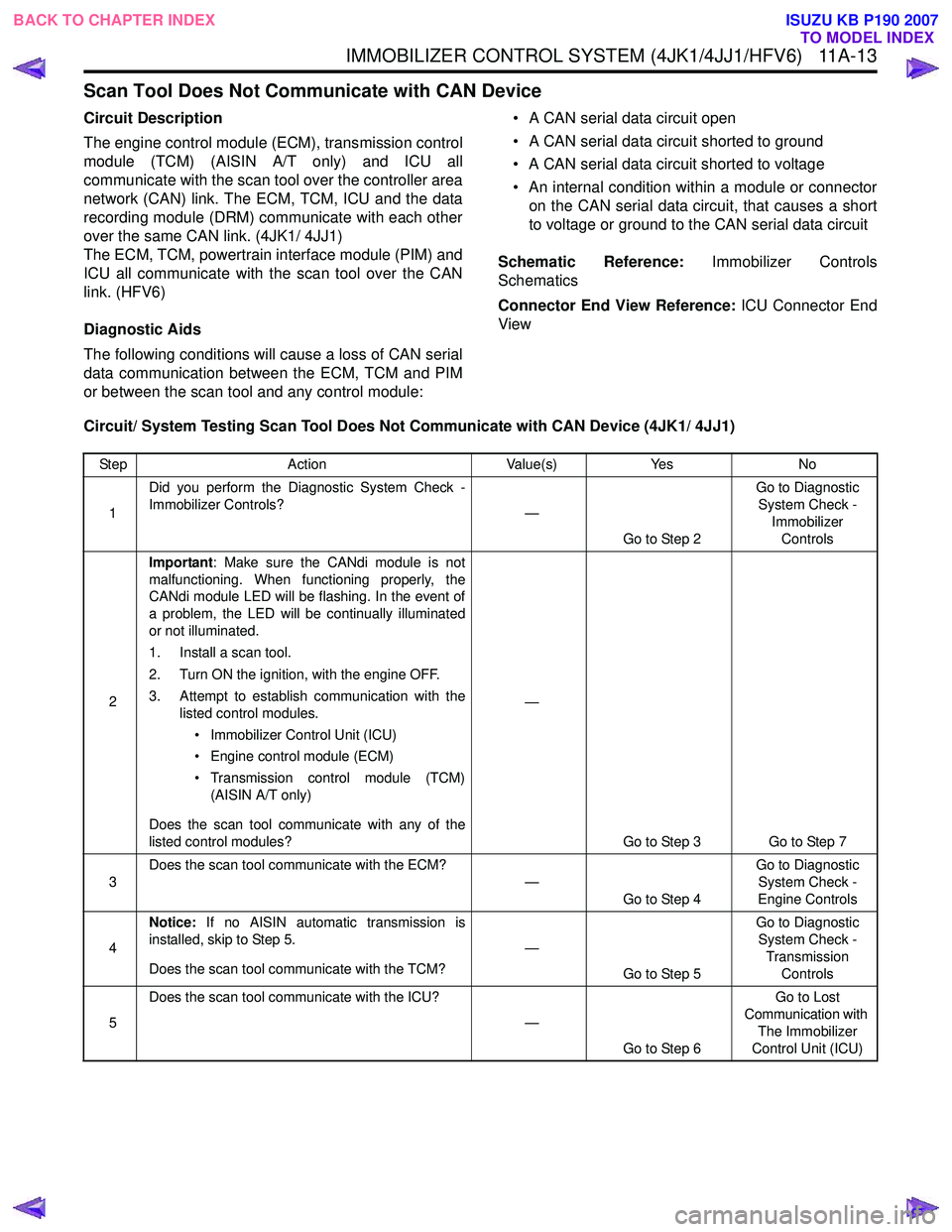
IMMOBILIZER CONTROL SYSTEM (4JK1/4JJ1/HFV6) 11A-13
Scan Tool Does Not Communicate with CAN Device
Circuit Description
The engine control module (ECM), transmission control
module (TCM) (AISIN A/T only) and ICU all
communicate with the scan tool over the controller area
network (CAN) link. The ECM, TCM, ICU and the data
recording module (DRM) communicate with each other
over the same CAN link. (4JK1/ 4JJ1)
The ECM, TCM, powertrain interface module (PIM) and
ICU all communicate with the scan tool over the CAN
link. (HFV6)
Diagnostic Aids
The following conditions will cause a loss of CAN serial
data communication between the ECM, TCM and PIM
or between the scan tool and any control module: • A CAN serial data circuit open
• A CAN serial data circuit shorted to ground
• A CAN serial data circuit shorted to voltage
• An internal condition within a module or connector on the CAN serial data circuit, that causes a short
to voltage or ground to the CAN serial data circuit
Schematic Reference: Immobilizer Controls
Schematics
Connector End View Reference: ICU Connector End
View
Circuit/ System Testing Scan Tool Does Not Communicate with CAN Device (4JK1/ 4JJ1)
Step Action Value(s)Yes No
1 Did you perform the Diagnostic System Check -
Immobilizer Controls? —
Go to Step 2 Go to Diagnostic
System Check - Immobilizer
Controls
2 Important
: Make sure the CANdi module is not
malfunctioning. When functioning properly, the
CANdi module LED will be flashing. In the event of
a problem, the LED will be continually illuminated
or not illuminated.
1. Install a scan tool.
2. Turn ON the ignition, with the engine OFF.
3. Attempt to establish communication with the listed control modules.
• Immobilizer Control Unit (ICU)
• Engine control module (ECM)
• Transmission control module (TCM) (AISIN A/T only)
Does the scan tool communicate with any of the
listed control modules? —
Go to Step 3 Go to Step 7
3 Does the scan tool communicate with the ECM?
—
Go to Step 4 Go to Diagnostic
System Check -
Engine Controls
4 Notice:
If no AISIN automatic transmission is
installed, skip to Step 5.
Does the scan tool communicate with the TCM? —
Go to Step 5 Go to Diagnostic
System Check - Transmission
Controls
5 Does the scan tool communicate with the ICU?
—Go to Step 6 Go to Lost
Communication with The Immobilizer
Control Unit (ICU)
BACK TO CHAPTER INDEX TO MODEL INDEX
ISUZU KB P190 2007
Page 5865 of 6020
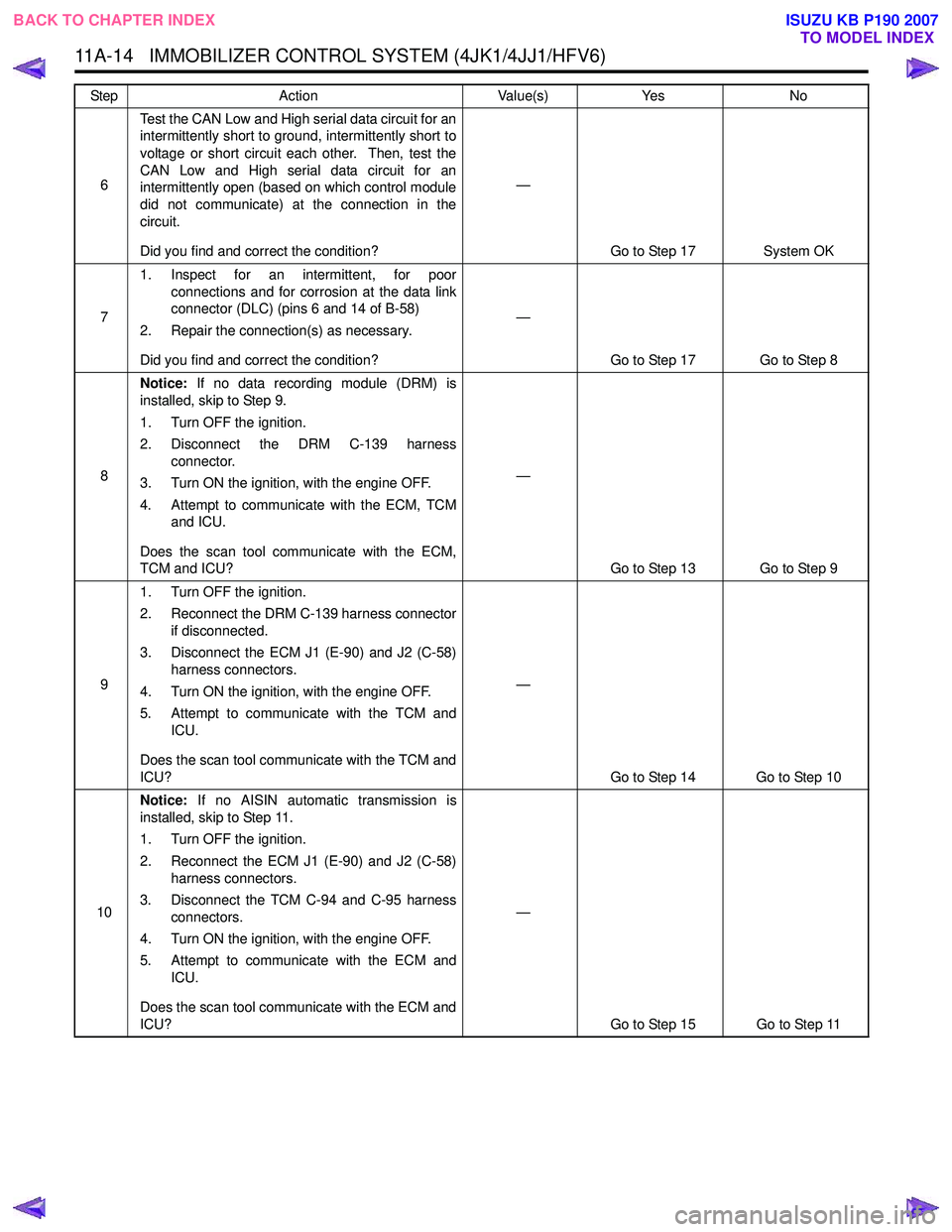
11A-14 IMMOBILIZER CONTROL SYSTEM (4JK1/4JJ1/HFV6)
6Test the CAN Low and High serial data circuit for an
intermittently short to ground, intermittently short to
voltage or short circuit each other. Then, test the
CAN Low and High serial data circuit for an
intermittently open (based on which control module
did not communicate) at the connection in the
circuit.
Did you find and correct the condition? —
Go to Step 17 System OK
7 1. Inspect for an intermittent, for poor
connections and for corrosion at the data link
connector (DLC) (pins 6 and 14 of B-58)
2. Repair the connection(s) as necessary.
Did you find and correct the condition? —
Go to Step 17 Go to Step 8
8 Notice:
If no data recording module (DRM) is
installed, skip to Step 9.
1. Turn OFF the ignition.
2. Disconnect the DRM C-139 harness connector.
3. Turn ON the ignition, with the engine OFF.
4. Attempt to communicate with the ECM, TCM and ICU.
Does the scan tool communicate with the ECM,
TCM and ICU? —
Go to Step 13 Go to Step 9
9 1. Turn OFF the ignition.
2. Reconnect the DRM C-139 harness connector if disconnected.
3. Disconnect the ECM J1 (E-90) and J2 (C-58) harness connectors.
4. Turn ON the ignition, with the engine OFF.
5. Attempt to communicate with the TCM and ICU.
Does the scan tool communicate with the TCM and
ICU? —
Go to Step 14 Go to Step 10
10 Notice:
If no AISIN automatic transmission is
installed, skip to Step 11.
1. Turn OFF the ignition.
2. Reconnect the ECM J1 (E-90) and J2 (C-58) harness connectors.
3. Disconnect the TCM C-94 and C-95 harness connectors.
4. Turn ON the ignition, with the engine OFF.
5. Attempt to communicate with the ECM and ICU.
Does the scan tool communicate with the ECM and
ICU? —
Go to Step 15 Go to Step 11
Step
Action Value(s)Yes No
BACK TO CHAPTER INDEX
TO MODEL INDEX
ISUZU KB P190 2007
Page 5866 of 6020
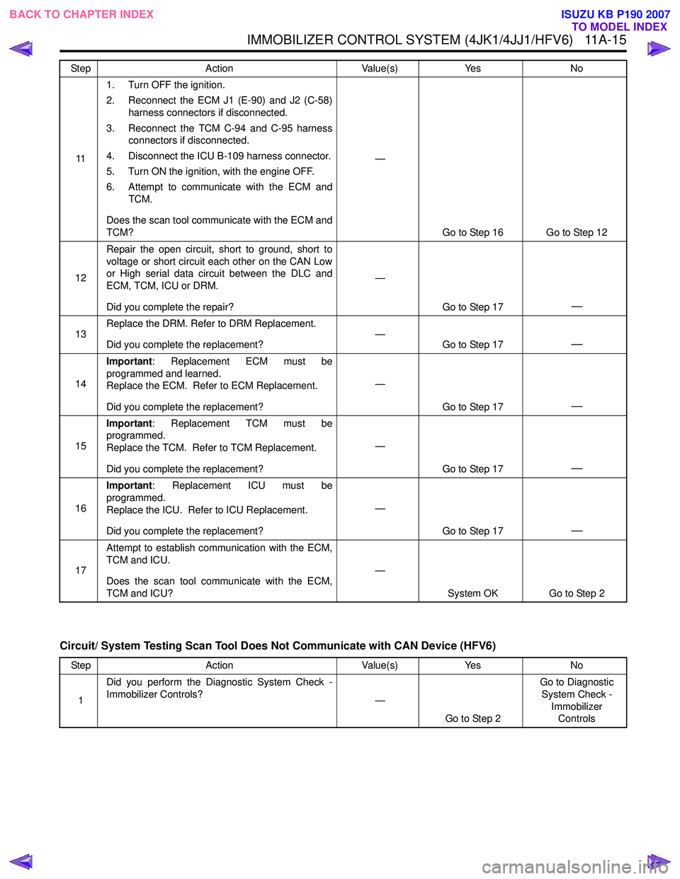
IMMOBILIZER CONTROL SYSTEM (4JK1/4JJ1/HFV6) 11A-15
Circuit/ System Testing Scan Tool Does Not Communicate with CAN Device (HFV6)
111. Turn OFF the ignition.
2. Reconnect the ECM J1 (E-90) and J2 (C-58) harness connectors if disconnected.
3. Reconnect the TCM C-94 and C-95 harness connectors if disconnected.
4. Disconnect the ICU B-109 harness connector.
5. Turn ON the ignition, with the engine OFF.
6. Attempt to communicate with the ECM and TCM.
Does the scan tool communicate with the ECM and
TCM? —
Go to Step 16 Go to Step 12
12 Repair the open circuit, short to ground, short to
voltage or short circuit each other on the CAN Low
or High serial data circuit between the DLC and
ECM, TCM, ICU or DRM.
Did you complete the repair? —
Go to Step 17
—
13Replace the DRM. Refer to DRM Replacement.
Did you complete the replacement? —
Go to Step 17—
14Important
: Replacement ECM must be
programmed and learned.
Replace the ECM. Refer to ECM Replacement.
Did you complete the replacement? —
Go to Step 17
—
15Important
: Replacement TCM must be
programmed.
Replace the TCM. Refer to TCM Replacement.
Did you complete the replacement? —
Go to Step 17
—
16Important
: Replacement ICU must be
programmed.
Replace the ICU. Refer to ICU Replacement.
Did you complete the replacement? —
Go to Step 17
—
17Attempt to establish communication with the ECM,
TCM and ICU.
Does the scan tool communicate with the ECM,
TCM and ICU? —
System OK Go to Step 2
Step Action Value(s)Yes No
1 Did you perform the Diagnostic System Check -
Immobilizer Controls? —
Go to Step 2 Go to Diagnostic
System Check - Immobilizer Controls
Step
Action Value(s)Yes No
BACK TO CHAPTER INDEX
TO MODEL INDEX
ISUZU KB P190 2007
Page 5867 of 6020
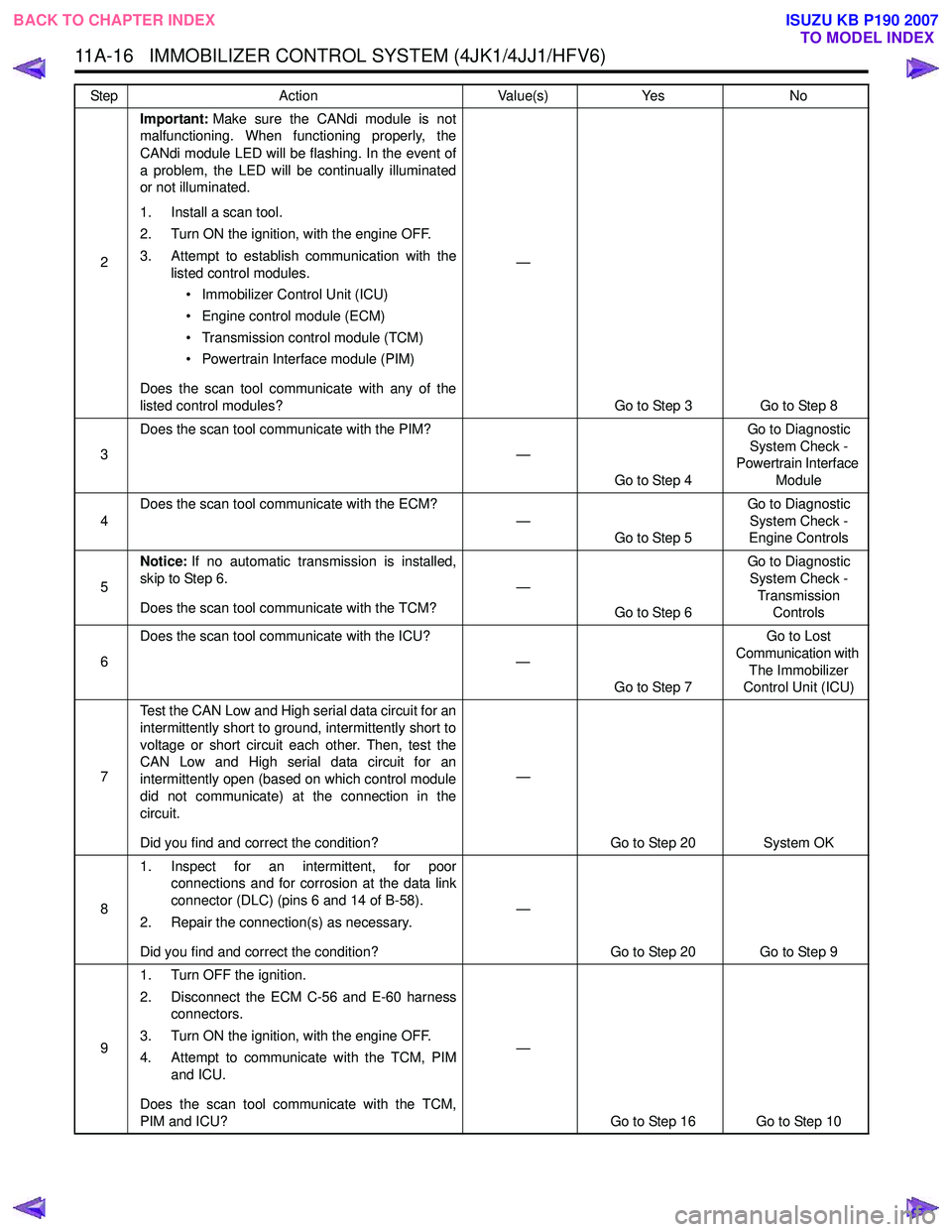
11A-16 IMMOBILIZER CONTROL SYSTEM (4JK1/4JJ1/HFV6)
2Important:
Make sure the CANdi module is not
malfunctioning. When functioning properly, the
CANdi module LED will be flashing. In the event of
a problem, the LED will be continually illuminated
or not illuminated.
1. Install a scan tool.
2. Turn ON the ignition, with the engine OFF.
3. Attempt to establish communication with the listed control modules.
• Immobilizer Control Unit (ICU)
• Engine control module (ECM)
• Transmission control module (TCM)
• Powertrain Interface module (PIM)
Does the scan tool communicate with any of the
listed control modules? —
Go to Step 3 Go to Step 8
3 Does the scan tool communicate with the PIM?
—
Go to Step 4 Go to Diagnostic
System Check -
Powertrain Interface
Module
4 Does the scan tool communicate with the ECM?
—Go to Step 5 Go to Diagnostic
System Check -
Engine Controls
5 Notice:
If no automatic transmission is installed,
skip to Step 6.
Does the scan tool communicate with the TCM? —
Go to Step 6 Go to Diagnostic
System Check - Transmission Controls
6 Does the scan tool communicate with the ICU?
—Go to Step 7 Go to Lost
Communication with The Immobilizer
Control Unit (ICU)
7 Test the CAN Low and High serial data circuit for an
intermittently short to ground, intermittently short to
voltage or short circuit each other. Then, test the
CAN Low and High serial data circuit for an
intermittently open (based on which control module
did not communicate) at the connection in the
circuit.
Did you find and correct the condition? —
Go to Step 20 System OK
8 1. Inspect for an intermittent, for poor
connections and for corrosion at the data link
connector (DLC) (pins 6 and 14 of B-58).
2. Repair the connection(s) as necessary.
Did you find and correct the condition? —
Go to Step 20 Go to Step 9
9 1. Turn OFF the ignition.
2. Disconnect the ECM C-56 and E-60 harness connectors.
3. Turn ON the ignition, with the engine OFF.
4. Attempt to communicate with the TCM, PIM and ICU.
Does the scan tool communicate with the TCM,
PIM and ICU? —
Go to Step 16 Go to Step 10
Step
Action Value(s)Yes No
BACK TO CHAPTER INDEX
TO MODEL INDEX
ISUZU KB P190 2007