Page 551 of 6020
FRONT WHEEL DRIVE 4C1-47
Important Operations
6. Hub nut
W rench : 5-8840-2117-0
7. Hub and disc assembly
Before disassembly, remove the disc brake caliper assembly
and hang it on the frame with wires.
Refer to Section “Brake” for disc brake caliper removal
procedure.
12. Bolt
13. Wheel Pin ; Front Hub
(1) Scribe mark on hub to disc before disassembly to insure proper assembly.
(2) Drive out the ABS sensor rotor using a metal bar and hammer through the two bolt holes.
• Discard the used ABS sensor rotor
Refer to the section Brake.
(3) Clamp hub and disc assembly in vise using protective pads
and remove six (6) disc to hub retaining bolts.
(4) Place hub on a suitable work surface and remove wheel
studs, as required, using a hammer.
BACK TO CHAPTER INDEX
TO MODEL INDEX
ISUZU KB P190 2007
Page 552 of 6020
4C1-48 FRONT WHEEL DRIVE
Inspection and Repair
Make necessary correction or parts replacement if wear, damage or any other abnormal conditions are found
through inspection.
For inspection and servicing of disc caliper, and relative parts, and ABS parts, refer to Section Brakes.
• Hub
• Hub bearing, oil seal
• Knuckle spindle
• Disc
• Caliper
• ABS sensor rotor
• Cap, Hub flange (4×4 model only),
Shim (4×4 model only), Snap ring (4×4
model only)
Visual Check
Check the following parts for wear, damage or other abnormal
conditions.
BACK TO CHAPTER INDEX
TO MODEL INDEX
ISUZU KB P190 2007
Page 553 of 6020
FRONT WHEEL DRIVE 4C1-49
Reassembly
Reassembly Steps
▲ 1 . W heel pin
▲ 2. Bolt
▲ 3. ABS sensor rotor
▲ 4. Inner bearing
▲ 5. Oil seal
▲ 6. Outer bearing
▲ 7. Hub and disc assembly
▲
8. Hub nut
▲ 9. Lock washer
▲1 0. Flange (4×4 model only)
▲11 . Snap ring and shim (4×4 model only)
12. Hub cap
▲1 3. Bolt
BACK TO CHAPTER INDEX
TO MODEL INDEX
ISUZU KB P190 2007
Page 554 of 6020
4C1-50 FRONT WHEEL DRIVE
Important Operations
1. Wheel Pin
( 1 ) Place hub on a wood workbench or a block of wood,
approx. 6” by 6” to protect the wheel stud ends and threads.
(2) Install wheel stud using a hammer.
Be sure wheel stud is started squarely and seats completely.
(3) Align index marks and install hub to disc.
2. Bolt
Torque N ⋅m (kgf ⋅m/lb ⋅ft)
1 03 ( 10.5/76)
3. ABS sensor rotor
( 1 ) Set a new ABS sensor rotor, if replacement is required.
(2) Install the ABS sensor rotor in the hub, using special tools.
Installer : 5-8840-2789-0
Grip : 5-8840-0007-0
Refer to the section Brake.
4. Inner Bearing
Outer race ; outer bearing
Install the outer race by driving it into the hub.
Installer : 5-8840-2 119-0
Grip : 5-8840-0007-0
BACK TO CHAPTER INDEX
TO MODEL INDEX
ISUZU KB P190 2007
Page 557 of 6020
FRONT WHEEL DRIVE 4C1-53
FRONT HUB AND DISC
(4 ×
××
×
4 Manual Locking Hub Model)
DISASSEMBLY
Refer to SECTION 3E “WHEELS AND TIRES” for wheel removal procedure
RTW 440LF00030 1
Disassembly Steps
� 1 . Bolt
2. Cover assembly
3. Snap ring and shim
4. Body assembly
5. Lock washer
� 6. Hub nut
� 7. Hub and disc assembly
8. Outer bearing
9. Oil seal
10. Inner bearing
11. ABS sensor rotor
� 1 2. Bolt
� 13. W heel pin
�
1 4. Clutch assembly
15. Snap ring
16. Knob
17. Compression spring
18. Follower
� 1 9. Retaining spring
20. X-ring
2 1. Snap ring
22. Inner assembly
23. Snap ring
24. Ring
25. Spacer
BACK TO CHAPTER INDEX
TO MODEL INDEX
ISUZU KB P190 2007
Page 559 of 6020
FRONT WHEEL DRIVE 4C1-55
12. Bolt
13. Wheel Pin ; Front Hub
( 1 ) Scribe mark on hub to disc before disassembly to insure
proper assembly.
(2) Drive out the ABS sensor rotor using a metal bar and hammer through the two bolt holes.
• Discard the used ABS sensor rotor
Refer to the section Brake.
(3) Clamp hub and disc assembly in vise using protective pads
and remove six (6) disc to hub retaining bolts.
(4) Place hub on a suitable work surface and remove wheel
studs, as required, using a hammer.
BACK TO CHAPTER INDEX
TO MODEL INDEX
ISUZU KB P190 2007
Page 560 of 6020
4C1-56 FRONT WHEEL DRIVE
INSPECTION AND REPAIR
Make necessary correction or parts replacement if wear, damage or any other abnormal conditions are found
through inspection.
For inspection and servicing of disc caliper, and relative parts, and ABS parts, refer to Section Brakes.
• Hub
• Hub bearing, oil seal
• Knuckle spindle
• Disc
• Caliper
• ABS sensor rotor
• Cap, Hub flange, Shim, Snap ring
• Free wheeling hub parts (Option)
• Clutch, Knob, follower, inner, ring and
spring
Visual Check
Check the following parts for wear, damage or other abnormal
conditions.
BACK TO CHAPTER INDEX
TO MODEL INDEX
ISUZU KB P190 2007
Page 561 of 6020
FRONT WHEEL DRIVE 4C1-57
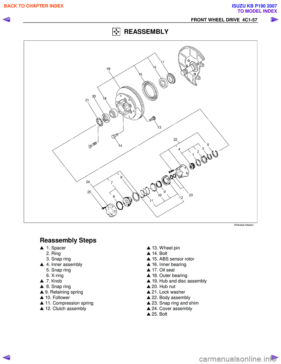
REASSEMBLY
RTW 440LF00040 1
Reassembly Steps
� 1 . Spacer
2. Ring
3. Snap ring
� 4. Inner assembly
5. Snap ring
6. X-ring
� 7. Knob
� 8. Snap ring
� 9. Retaining spring
� 1 0. Follower
� 11 . Compression spring
� 1 2. Clutch assembly
�
1 3. W heel pin
� 1 4. Bolt
� 1 5. ABS sensor rotor
� 1 6. Inner bearing
� 1 7. Oil seal
� 1 8. Outer bearing
� 1 9. Hub and disc assembly
� 20. Hub nut
� 21. Lock washer
� 22. Body assembly
� 23. Snap ring and shim
� 24. Cover assembly
� 25. Bolt
BACK TO CHAPTER INDEX
TO MODEL INDEX
ISUZU KB P190 2007


 Place hub on a wood workbench or a block of wood,
approx. 6” by 6” to protect the wheel stud ends and threads.
(2) Install")

DISASSEMBLY
Refer to SECTION 3E “WHEELS AND TIRES” for wheel removal procedure
RTW 440LF000")
 Scribe mark on hub to disc before disassembly to insure
proper assembly.
(2) Drive out the ABS sensor rotor using a m")