2007 ISUZU KB P190 oil filter
[x] Cancel search: oil filterPage 966 of 6020

6C – 2 FUEL SYSTEM
MAIN DATA AND SPECIFICATIONS
Description Item
4JA1T (L) 4JA1TC 4JH1TC
Injection pump type Bosch distributor
VE type Bosch distributor VP44 type
Governor type
Mechanical variable
(Half speed oil pressure) Electrical controled
Timer type
Oil pressure Electrical controled
Fuel feed pump type Vane with input shaft
Injection nozzle type Hole type
Number of injection nozzle orifices 5
Injection nozzle orifices
Inside diameter mm (in) 0.19 (0.0075) 0.17 (0.0067) 0.21 (0.0083)
19.1 (195) 19.0 (194) 19.5 (199) Injection nozzle designed operating
pressure MPa (kg/cm2) 1st
2nd 25.0 (255)
33.5 (328) 33.8 (331)
Main fuel filter type Disposable cartridge paper element
Precautions
When working on the fuel system, there are several things
to keep in mind:
•
Any time the fuel system is being worked on,
disconnect the negative battery cable except fo
r
those tests where battery voltage is required.
•
Always keep a dry chemical (Class B) fire
extinguisher near the work area.
• Replace all pipes with the same pipe and fittings that
were removed.
• Clean and inspect “O” rings. Replace if required.
•
Always relieve the line pressure before servicing any
fuel system components.
• Do not attempt repairs on the fuel system until you
have read the instructions and checked the pictures
relating to that repair.
• Adhere to all Notices and Cautions.
NOTE:
Injection nozzle adjustment is possible only on the 4JA1L
engine.
BACK TO CHAPTER INDEX
TO MODEL INDEX
ISUZU KB P190 2007
Page 983 of 6020

FUEL SYSTEM 6C – 19
7. Power Steering Pump Bracket
6C-4 8. Throttle Position Sensor Harness Connector
(4JA1TC/4JH1TC only) Disconnect the harness connector from the throttle
position sensor.
9. Oil Level Gauge
10. Fuel Pipe 1) Disconnect the fuel hoses from the fuel filter or priming pump.
2) Disconnect the fuel hoses from the injection pump.
11. Fuel Filter Assembly (Except EURO III model)
6C-5
12. Fuel Filter Bracket (Except EURO III model)
13. Leak Off Hose
Disconnect the leak off hose at the injection pump.
14. Injection Pipe Clip
15. Injection Pipe
1) Loosen the injection pipe sleeve nuts at the delivery valve side and the injection nozzle side.
Note:
Do not apply excessive force to the injection pipes.
2) Loosen the injection pipe clip.
3) Remove the injection pipes.
Note:
Plug the delivery holder ports with the caps to prevent
the entry of foreign material.
16. Intake Manifold 1) Remove the EGR valve from the intake manifold and EGR pipe.
2) Loosen the intake rubber hoses clip.
3) Loosen the intake manifold bolts and nuts.
17. Injection Pump Cover (4JA1TC/4JH1TC only)
BACK TO CHAPTER INDEX
TO MODEL INDEX
ISUZU KB P190 2007
Page 987 of 6020

FUEL SYSTEM 6C – 23
6. Injection Pipe
Install the injection pipe.
Injection Pipe Torque N·m(kg·m / lb ft)
29 (3.0 / 22)
Nozzle Side (4JA1TC/4JH1TC) N·m(kg·m / lb ft)
29 (3.0 / 22)
Pump Side (4JA1TC/4JH1TC) N·m(kg·m / lb ft)
40 (4.1 / 30)
7. Injection Pipe Clip Install the injection pipe clip.
Note:
Make absolutely sure that the clip is correctly
positioned.
Injection Pipe Clip Torque N·m(kg·m / lb in)
8 (0.8 / 69)
8. Leak Off Pipe and Leak Off Hose
Install the leak off pipe to injection nozzle and connect the
leak off hose to the injection pump.
9. Fuel Filter Bracket (Except EURO III model)
Install the fuel filter bracket and tighten bolts to the
specified torque.
Fuel Filter Bracket Bolts Torque N·m(kg·m / lb ft)
21 (2.1 / 15)
10. Fuel Filter Assembly (Except EURO III model) Install the fuel filter assembly to bracket and tighten bolts
to the specified torque.
Fuel Filter Assembly Bolts
Torque N·m(kg·m / lb ft)
21 (2.1 / 15)
11. Fuel Pipe
1) Connect the fuel hoses to the fuel filter or priming pump.
2) Connect the fuel hoses to the injection pump.
12. Oil Level Gauge Install the oil level gauge and tighten bolts to the specified
torque.
Oil Level Gauge Bolts
Torque N·m(kg·m / lb ft)
M8: 19 (1.9 / 14)
M6: 8 (0.8/6 lb in)
BACK TO CHAPTER INDEX
TO MODEL INDEX
ISUZU KB P190 2007
Page 1082 of 6020
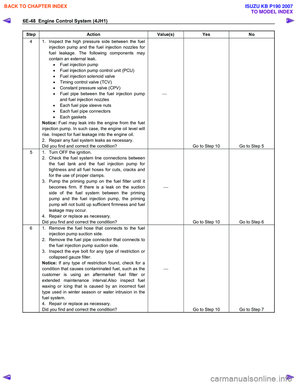
6E-48 Engine Control System (4JH1)
Step Action Value(s) Yes No
4 1. Inspect the high pressure side between the fuel
injection pump and the fuel injection nozzles for
fuel leakage. The following components may
contain an external leak. • Fuel injection pump
• Fuel injection pump control unit (PCU)
• Fuel injection solenoid valve
• Timing control valve (TCV)
• Constant pressure valve (CPV)
• Fuel pipe between the fuel injection pump
and fuel injection nozzles
• Each fuel pipe sleeve nuts
• Each fuel pipe connectors
• Each gaskets
Notice: Fuel may leak into the engine from the fuel
injection pump. In such case, the engine oil level will
rise. Inspect for fuel leakage into the engine oil.
2. Repair any fuel system leaks as necessary.
Did you find and correct the condition?
Go to Step 10 Go to Step 5
5 1. Turn OFF the ignition. 2. Check the fuel system line connections between the fuel tank and the fuel injection pump for
tightness and all fuel hoses for cuts, cracks and
for the use of proper clamps.
3. Pump the priming pump on the fuel filter until it becomes firm. If there is a leak on the suction
side of the fuel system between the priming
pump and the fuel injection pump, the priming
pump will not build up sufficient firmness and fuel
leakage may occur.
4. Repair or replace as necessary.
Did you find and correct the condition?
Go to Step 10 Go to Step 6
6 1. Remove the fuel hose that connects to the fuel injection pump suction side.
2. Remove the fuel pipe connector that connects to the fuel injection pump suction side.
3. Inspect the eye bolt for any type of restriction or collapsed gauze filter.
Notice: If any type of restriction found, check for a
condition that causes contaminated fuel, such as the
customer is using an aftermarket fuel filter or
extended maintenance interval.Also inspect fuel
waxing or icing that is caused by an incorrect fuel
type used in winter season or water intrusion in the
fuel system.
4. Repair or replace as necessary.
Did you find and correct the condition?
Go to Step 10 Go to Step 7
BACK TO CHAPTER INDEX
TO MODEL INDEX
ISUZU KB P190 2007
Page 1293 of 6020
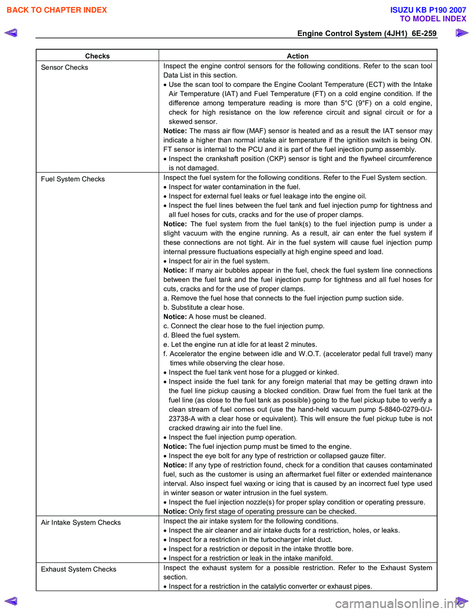
Engine Control System (4JH1) 6E-259
Checks Action
Sensor Checks Inspect the engine control sensors for the following conditions. Refer to the scan tool
Data List in this section.
• Use the scan tool to compare the Engine Coolant Temperature (ECT) with the Intake
Air Temperature (IAT) and Fuel Temperature (FT) on a cold engine condition. If the
difference among temperature reading is more than 5°C (9°F) on a cold engine,
check for high resistance on the low reference circuit and signal circuit or for a
skewed sensor.
Notice: The mass air flow (MAF) sensor is heated and as a result the IAT sensor may
indicate a higher than normal intake air temperature if the ignition switch is being ON.
FT sensor is internal to the PCU and it is part of the fuel injection pump assembly.
• Inspect the crankshaft position (CKP) sensor is tight and the flywheel circumference
is not damaged.
Fuel System Checks Inspect the fuel system for the following conditions. Refer to the Fuel System section.
• Inspect for water contamination in the fuel.
• Inspect for external fuel leaks or fuel leakage into the engine oil.
• Inspect the fuel lines between the fuel tank and fuel injection pump for tightness and
all fuel hoses for cuts, cracks and for the use of proper clamps.
Notice: The fuel system from the fuel tank(s) to the fuel injection pump is under a
slight vacuum with the engine running. As a result, air can enter the fuel system if
these connections are not tight. Air in the fuel system will cause fuel injection pump
internal pressure fluctuations especially at high engine speed and load.
• Inspect for air in the fuel system.
Notice: If many air bubbles appear in the fuel, check the fuel system line connections
between the fuel tank and the fuel injection pump for tightness and all fuel hoses for
cuts, cracks and for the use of proper clamps.
a. Remove the fuel hose that connects to the fuel injection pump suction side.
b. Substitute a clear hose.
Notice: A hose must be cleaned.
c. Connect the clear hose to the fuel injection pump.
d. Bleed the fuel system.
e. Let the engine run at idle for at least 2 minutes.
f. Accelerator the engine between idle and W .O.T. (accelerator pedal full travel) many times while observing the clear hose.
• Inspect the fuel tank vent hose for a plugged or kinked.
• Inspect inside the fuel tank for any foreign material that may be getting drawn into
the fuel line pickup causing a blocked condition. Draw fuel from the fuel tank at the
fuel line (as close to the fuel tank as possible) going to the fuel pickup tube to verify a
clean stream of fuel comes out (use the hand-held vacuum pump 5-8840-0279-0/J-
23738-A with a clear hose or equivalent). This will ensure the fuel pickup tube is not
cracked drawing air into the fuel line.
• Inspect the fuel injection pump operation.
Notice: The fuel injection pump must be timed to the engine.
• Inspect the eye bolt for any type of restriction or collapsed gauze filter.
Notice: If any type of restriction found, check for a condition that causes contaminated
fuel, such as the customer is using an aftermarket fuel filter or extended maintenance
interval. Also inspect fuel waxing or icing that is caused by an incorrect fuel type used
in winter season or water intrusion in the fuel system.
• Inspect the fuel injection nozzle(s) for proper splay condition or operating pressure.
Notice: Only first stage of operating pressure can be checked.
Air Intake System Checks Inspect the air intake system for the following conditions.
• Inspect the air cleaner and air intake ducts for a restriction, holes, or leaks.
• Inspect for a restriction in the turbocharger inlet duct.
• Inspect for a restriction or deposit in the intake throttle bore.
• Inspect for a restriction or leak in the intake manifold.
Exhaust System Checks Inspect the exhaust system for a possible restriction. Refer to the Exhaust System
section.
• Inspect for a restriction in the catalytic converter or exhaust pipes.
BACK TO CHAPTER INDEX
TO MODEL INDEX
ISUZU KB P190 2007
Page 1295 of 6020
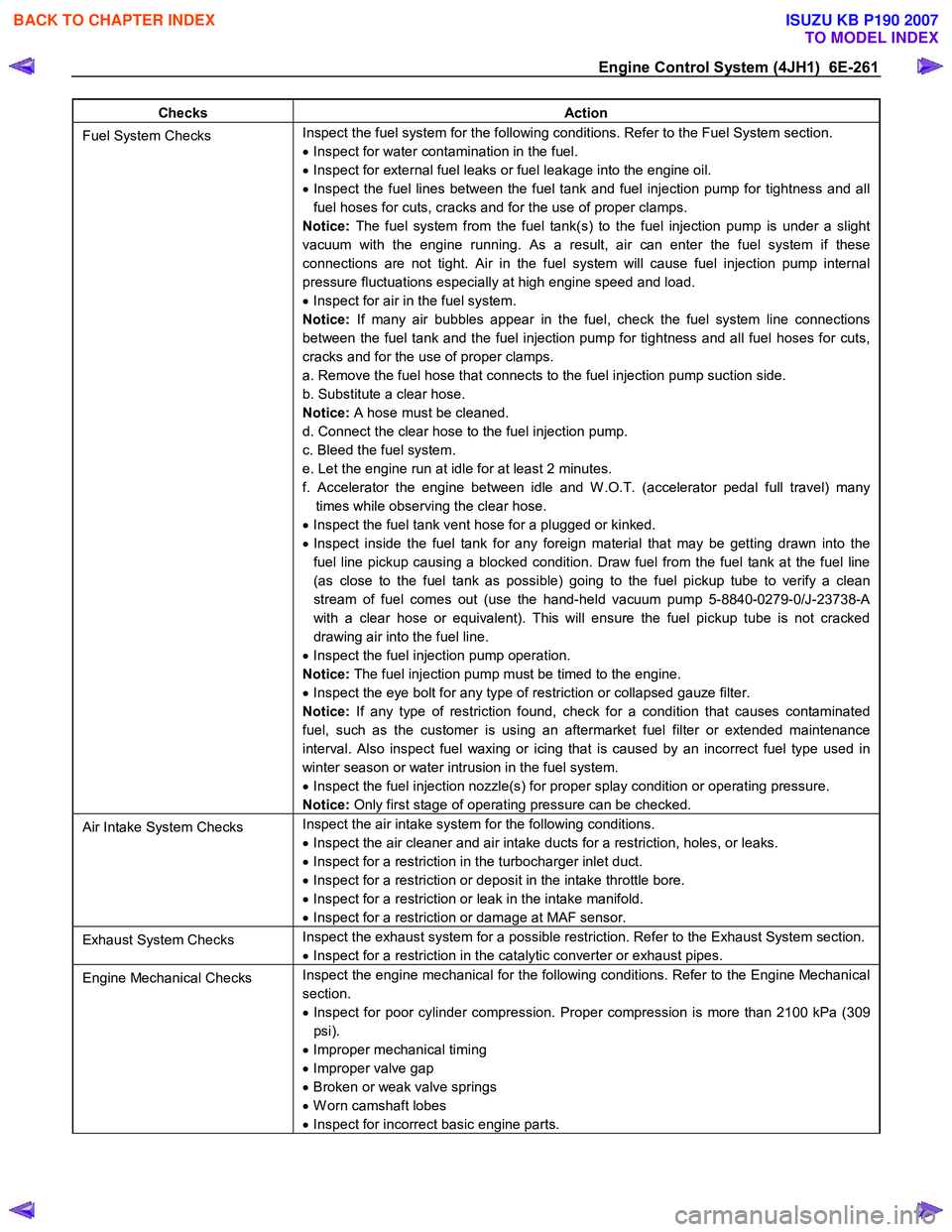
Engine Control System (4JH1) 6E-261
Checks Action
Fuel System Checks Inspect the fuel system for the following conditions. Refer to the Fuel System section.
• Inspect for water contamination in the fuel.
• Inspect for external fuel leaks or fuel leakage into the engine oil.
• Inspect the fuel lines between the fuel tank and fuel injection pump for tightness and all
fuel hoses for cuts, cracks and for the use of proper clamps.
Notice: The fuel system from the fuel tank(s) to the fuel injection pump is under a slight
vacuum with the engine running. As a result, air can enter the fuel system if these
connections are not tight. Air in the fuel system will cause fuel injection pump internal
pressure fluctuations especially at high engine speed and load.
• Inspect for air in the fuel system.
Notice: If many air bubbles appear in the fuel, check the fuel system line connections
between the fuel tank and the fuel injection pump for tightness and all fuel hoses for cuts,
cracks and for the use of proper clamps.
a. Remove the fuel hose that connects to the fuel injection pump suction side.
b. Substitute a clear hose.
Notice: A hose must be cleaned.
d. Connect the clear hose to the fuel injection pump.
c. Bleed the fuel system.
e. Let the engine run at idle for at least 2 minutes.
f. Accelerator the engine between idle and W .O.T. (accelerator pedal full travel) many times while observing the clear hose.
• Inspect the fuel tank vent hose for a plugged or kinked.
• Inspect inside the fuel tank for any foreign material that may be getting drawn into the
fuel line pickup causing a blocked condition. Draw fuel from the fuel tank at the fuel line
(as close to the fuel tank as possible) going to the fuel pickup tube to verify a clean
stream of fuel comes out (use the hand-held vacuum pump 5-8840-0279-0/J-23738-A
with a clear hose or equivalent). This will ensure the fuel pickup tube is not cracked
drawing air into the fuel line.
• Inspect the fuel injection pump operation.
Notice: The fuel injection pump must be timed to the engine.
• Inspect the eye bolt for any type of restriction or collapsed gauze filter.
Notice: If any type of restriction found, check for a condition that causes contaminated
fuel, such as the customer is using an aftermarket fuel filter or extended maintenance
interval. Also inspect fuel waxing or icing that is caused by an incorrect fuel type used in
winter season or water intrusion in the fuel system.
• Inspect the fuel injection nozzle(s) for proper splay condition or operating pressure.
Notice: Only first stage of operating pressure can be checked.
Air Intake System Checks Inspect the air intake system for the following conditions.
• Inspect the air cleaner and air intake ducts for a restriction, holes, or leaks.
• Inspect for a restriction in the turbocharger inlet duct.
• Inspect for a restriction or deposit in the intake throttle bore.
• Inspect for a restriction or leak in the intake manifold.
• Inspect for a restriction or damage at MAF sensor.
Exhaust System Checks Inspect the exhaust system for a possible restriction. Refer to the Exhaust System section.
• Inspect for a restriction in the catalytic converter or exhaust pipes.
Engine Mechanical Checks Inspect the engine mechanical for the following conditions. Refer to the Engine Mechanical
section.
• Inspect for poor cylinder compression. Proper compression is more than 2100 kPa (309
psi).
• Improper mechanical timing
• Improper valve gap
• Broken or weak valve springs
• W orn camshaft lobes
• Inspect for incorrect basic engine parts.
BACK TO CHAPTER INDEX
TO MODEL INDEX
ISUZU KB P190 2007
Page 1297 of 6020
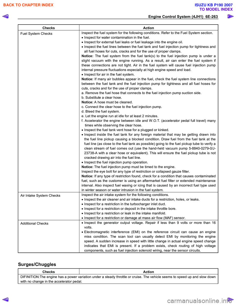
Engine Control System (4JH1) 6E-263
Checks Action
Fuel System Checks Inspect the fuel system for the following conditions. Refer to the Fuel System section.
• Inspect for water contamination in the fuel.
• Inspect for external fuel leaks or fuel leakage into the engine oil.
• Inspect the fuel lines between the fuel tank and fuel injection pump for tightness and
all fuel hoses for cuts, cracks and for the use of proper clamps.
Notice: The fuel system from the fuel tank(s) to the fuel injection pump is under a
slight vacuum with the engine running. As a result, air can enter the fuel system if
these connections are not tight. Air in the fuel system will cause fuel injection pump
internal pressure fluctuations especially at high engine speed and load.
• Inspect for air in the fuel system.
Notice: If many air bubbles appear in the fuel, check the fuel system line connections
between the fuel tank and the fuel injection pump for tightness and all fuel hoses for
cuts, cracks and for the use of proper clamps.
a. Remove the fuel hose that connects to the fuel injection pump suction side.
b. Substitute a clear hose.
Notice: A hose must be cleaned.
c. Connect the clear hose to the fuel injection pump.
d. Bleed the fuel system.
e. Let the engine run at idle for at least 2 minutes.
f. Accelerator the engine between idle and W .O.T. (accelerator pedal full travel) many times while observing the clear hose.
• Inspect the fuel tank vent hose for a plugged or kinked.
• Inspect inside the fuel tank for any foreign material that may be getting drawn into
the fuel line pickup causing a blocked condition. Draw fuel from the fuel tank at the
fuel line (as close to the fuel tank as possible) going to the fuel pickup tube to verify a
clean stream of fuel comes out (use the hand-held vacuum pump 5-8840-0279-0/J-
23738-A with a clear hose or equivalent). This will ensure the fuel pickup tube is not
cracked drawing air into the fuel line.
• Inspect the fuel injection pump operation.
Notice: The fuel injection pump must be timed to the engine.
Inspect the eye bolt for any type of restriction or collapsed gauze filter.
Notice: If any type of restriction found, check for a condition that causes contaminated
fuel, such as the customer is using an aftermarket fuel filter or extended maintenance
interval. Also inspect fuel waxing or icing that is caused by an incorrect fuel type used
in winter season or water intrusion in the fuel system.
Air Intake System Checks Inspect the air intake system for the following conditions.
• Inspect the air cleaner and air intake ducts for a restriction, holes, or leaks.
• Inspect for a restriction in the turbocharger inlet duct.
• Inspect for a restriction or deposit in the intake throttle bore.
• Inspect for a restriction or leak in the intake manifold.
• Inspect for a restriction or damage at mass air flow (MAF) sensor.
Additional Checks •
Inspect the generator output voltage. Repair if less than 9 volts or more than 16
volts.
• Electromagnetic interference (EMI) on the reference circuit can cause an engine
miss condition. The scan tool can usually detect EMI by monitoring the engine
speed. A sudden increase in speed with little change in actual engine speed change
indicates that EMI is present. If a problem exists, check routing of high voltage
components, such as fuel injection solenoid wiring, near the sensor circuits.
Surges/Chuggles
Checks Action
DIFINITION:The engine has a power variation under a steady throttle or cruise. The vehicle seems to speed up and slow down
with no change in the accelerator pedal.
BACK TO CHAPTER INDEX
TO MODEL INDEX
ISUZU KB P190 2007
Page 1299 of 6020
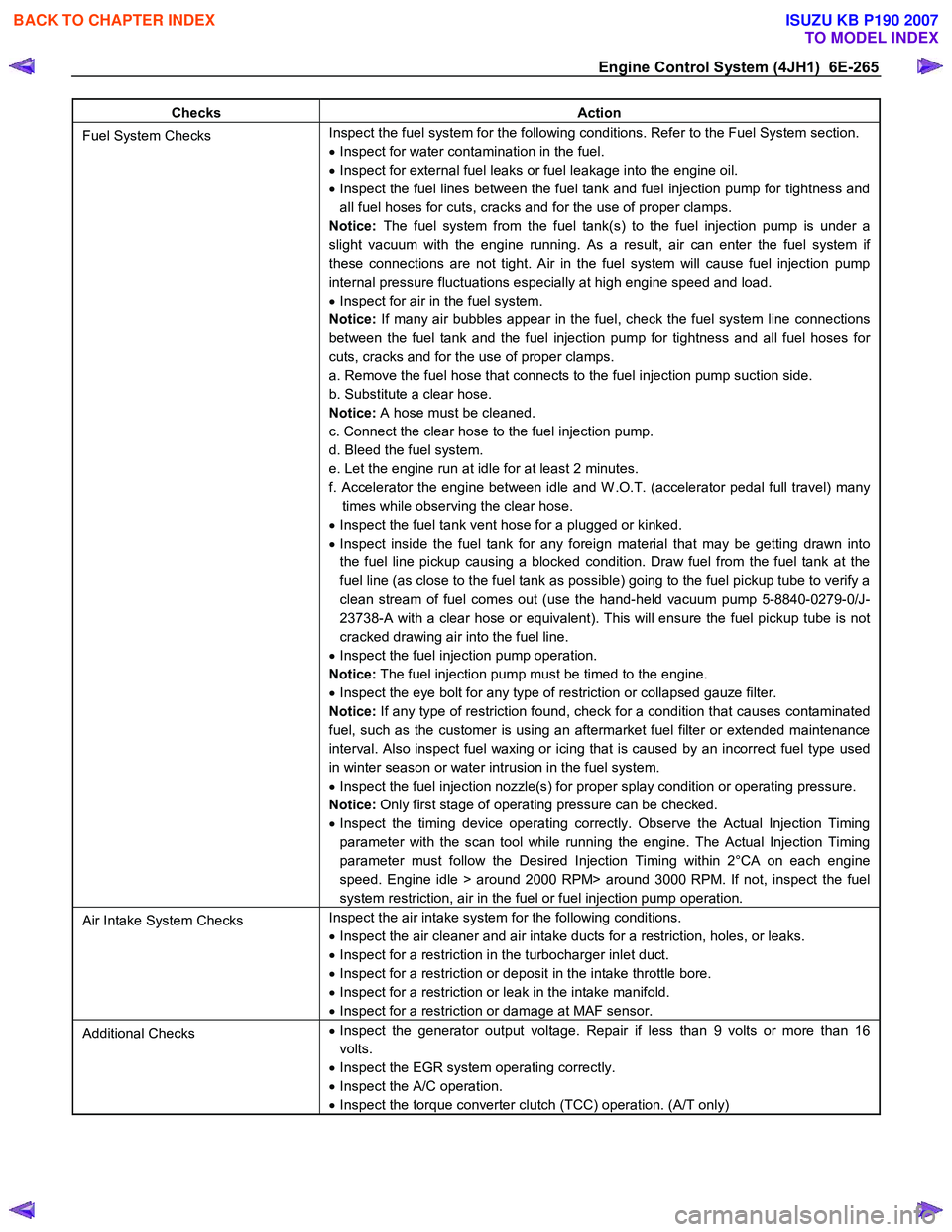
Engine Control System (4JH1) 6E-265
Checks Action
Fuel System Checks Inspect the fuel system for the following conditions. Refer to the Fuel System section.
• Inspect for water contamination in the fuel.
• Inspect for external fuel leaks or fuel leakage into the engine oil.
• Inspect the fuel lines between the fuel tank and fuel injection pump for tightness and
all fuel hoses for cuts, cracks and for the use of proper clamps.
Notice: The fuel system from the fuel tank(s) to the fuel injection pump is under a
slight vacuum with the engine running. As a result, air can enter the fuel system if
these connections are not tight. Air in the fuel system will cause fuel injection pump
internal pressure fluctuations especially at high engine speed and load.
• Inspect for air in the fuel system.
Notice: If many air bubbles appear in the fuel, check the fuel system line connections
between the fuel tank and the fuel injection pump for tightness and all fuel hoses for
cuts, cracks and for the use of proper clamps.
a. Remove the fuel hose that connects to the fuel injection pump suction side.
b. Substitute a clear hose.
Notice: A hose must be cleaned.
c. Connect the clear hose to the fuel injection pump.
d. Bleed the fuel system.
e. Let the engine run at idle for at least 2 minutes.
f. Accelerator the engine between idle and W .O.T. (accelerator pedal full travel) many times while observing the clear hose.
• Inspect the fuel tank vent hose for a plugged or kinked.
• Inspect inside the fuel tank for any foreign material that may be getting drawn into
the fuel line pickup causing a blocked condition. Draw fuel from the fuel tank at the
fuel line (as close to the fuel tank as possible) going to the fuel pickup tube to verify a
clean stream of fuel comes out (use the hand-held vacuum pump 5-8840-0279-0/J-
23738-A with a clear hose or equivalent). This will ensure the fuel pickup tube is not
cracked drawing air into the fuel line.
• Inspect the fuel injection pump operation.
Notice: The fuel injection pump must be timed to the engine.
• Inspect the eye bolt for any type of restriction or collapsed gauze filter.
Notice: If any type of restriction found, check for a condition that causes contaminated
fuel, such as the customer is using an aftermarket fuel filter or extended maintenance
interval. Also inspect fuel waxing or icing that is caused by an incorrect fuel type used
in winter season or water intrusion in the fuel system.
• Inspect the fuel injection nozzle(s) for proper splay condition or operating pressure.
Notice: Only first stage of operating pressure can be checked.
• Inspect the timing device operating correctly. Observe the Actual Injection Timing
parameter with the scan tool while running the engine. The Actual Injection Timing
parameter must follow the Desired Injection Timing within 2°CA on each engine
speed. Engine idle > around 2000 RPM> around 3000 RPM. If not, inspect the fuel
system restriction, air in the fuel or fuel injection pump operation.
Air Intake System Checks Inspect the air intake system for the following conditions.
• Inspect the air cleaner and air intake ducts for a restriction, holes, or leaks.
• Inspect for a restriction in the turbocharger inlet duct.
• Inspect for a restriction or deposit in the intake throttle bore.
• Inspect for a restriction or leak in the intake manifold.
• Inspect for a restriction or damage at MAF sensor.
Additional Checks •
Inspect the generator output voltage. Repair if less than 9 volts or more than 16
volts.
• Inspect the EGR system operating correctly.
• Inspect the A/C operation.
• Inspect the torque converter clutch (TCC) operation. (A/T only)
BACK TO CHAPTER INDEX
TO MODEL INDEX
ISUZU KB P190 2007