2007 ISUZU KB P190 oil filter
[x] Cancel search: oil filterPage 1301 of 6020
Engine Control System (4JH1) 6E-267
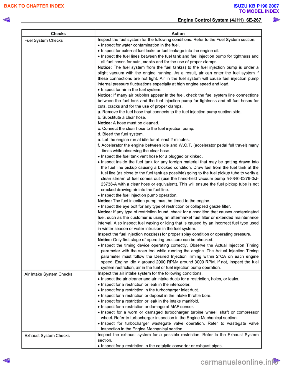
Checks Action
Fuel System Checks Inspect the fuel system for the following conditions. Refer to the Fuel System section.
• Inspect for water contamination in the fuel.
• Inspect for external fuel leaks or fuel leakage into the engine oil.
• Inspect the fuel lines between the fuel tank and fuel injection pump for tightness and
all fuel hoses for cuts, cracks and for the use of proper clamps.
Notice: The fuel system from the fuel tank(s) to the fuel injection pump is under a
slight vacuum with the engine running. As a result, air can enter the fuel system if
these connections are not tight. Air in the fuel system will cause fuel injection pump
internal pressure fluctuations especially at high engine speed and load.
• Inspect for air in the fuel system.
Notice: If many air bubbles appear in the fuel, check the fuel system line connections
between the fuel tank and the fuel injection pump for tightness and all fuel hoses for
cuts, cracks and for the use of proper clamps.
a. Remove the fuel hose that connects to the fuel injection pump suction side.
b. Substitute a clear hose.
Notice: A hose must be cleaned.
c. Connect the clear hose to the fuel injection pump.
d. Bleed the fuel system.
e. Let the engine run at idle for at least 2 minutes.
f. Accelerator the engine between idle and W .O.T. (accelerator pedal full travel) many times while observing the clear hose.
• Inspect the fuel tank vent hose for a plugged or kinked.
• Inspect inside the fuel tank for any foreign material that may be getting drawn into
the fuel line pickup causing a blocked condition. Draw fuel from the fuel tank at the
fuel line (as close to the fuel tank as possible) going to the fuel pickup tube to verify a
clean stream of fuel comes out (use the hand-held vacuum pump 5-8840-0279-0/J-
23738-A with a clear hose or equivalent). This will ensure the fuel pickup tube is not
cracked drawing air into the fuel line.
• Inspect the fuel injection pump operation.
Notice: The fuel injection pump must be timed to the engine.
• Inspect the eye bolt for any type of restriction or collapsed gauze filter.
Notice: If any type of restriction found, check for a condition that causes contaminated
fuel, such as the customer is using an aftermarket fuel filter or extended maintenance
interval. Also inspect fuel waxing or icing that is caused by an incorrect fuel type used
in winter season or water intrusion in the fuel system.
Inspect the fuel injection nozzle(s) for proper splay condition or operating pressure.
Notice: Only first stage of operating pressure can be checked.
• Inspect the timing device operating correctly. Observe the Actual Injection Timing
parameter with the scan tool while running the engine. The Actual Injection Timing
parameter must follow the Desired Injection Timing within 2°CA on each engine
speed. Engine idle > around 2000 RPM> around 3000 RPM. If not, inspect the fuel
system restriction, air in the fuel or fuel injection pump operation.
Air Intake System Checks Inspect the air intake system for the following conditions.
• Inspect the air cleaner and air intake ducts for a restriction, holes, or leaks.
• Inspect for a restriction or leak in the intercooler.
• Inspect for a restriction in the turbocharger inlet duct.
• Inspect for a restriction or deposit in the intake throttle bore.
• Inspect for a restriction or leak in the intake manifold.
• Inspect for a restriction or damage at MAF sensor.
• Inspect for a worn or damaged turbocharger turbine wheel, shaft or compressor
wheel. Refer to turbocharger inspection in the Engine Mechanical section.
• Inspect for turbocharger wastegate valve operation. Refer to wastegate valve
inspection in the Engine Mechanical section.
Exhaust System Checks Inspect the exhaust system for a possible restriction. Refer to the Exhaust System
section.
• Inspect for a restriction in the catalytic converter or exhaust pipes.
BACK TO CHAPTER INDEX
TO MODEL INDEX
ISUZU KB P190 2007
Page 1303 of 6020
Engine Control System (4JH1) 6E-269
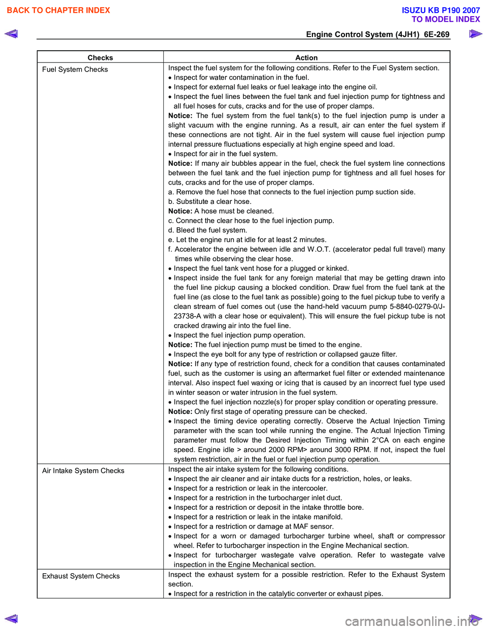
Checks Action
Fuel System Checks Inspect the fuel system for the following conditions. Refer to the Fuel System section.
• Inspect for water contamination in the fuel.
• Inspect for external fuel leaks or fuel leakage into the engine oil.
• Inspect the fuel lines between the fuel tank and fuel injection pump for tightness and
all fuel hoses for cuts, cracks and for the use of proper clamps.
Notice: The fuel system from the fuel tank(s) to the fuel injection pump is under a
slight vacuum with the engine running. As a result, air can enter the fuel system if
these connections are not tight. Air in the fuel system will cause fuel injection pump
internal pressure fluctuations especially at high engine speed and load.
• Inspect for air in the fuel system.
Notice: If many air bubbles appear in the fuel, check the fuel system line connections
between the fuel tank and the fuel injection pump for tightness and all fuel hoses for
cuts, cracks and for the use of proper clamps.
a. Remove the fuel hose that connects to the fuel injection pump suction side.
b. Substitute a clear hose.
Notice: A hose must be cleaned.
c. Connect the clear hose to the fuel injection pump.
d. Bleed the fuel system.
e. Let the engine run at idle for at least 2 minutes.
f. Accelerator the engine between idle and W .O.T. (accelerator pedal full travel) many times while observing the clear hose.
• Inspect the fuel tank vent hose for a plugged or kinked.
• Inspect inside the fuel tank for any foreign material that may be getting drawn into
the fuel line pickup causing a blocked condition. Draw fuel from the fuel tank at the
fuel line (as close to the fuel tank as possible) going to the fuel pickup tube to verify a
clean stream of fuel comes out (use the hand-held vacuum pump 5-8840-0279-0/J-
23738-A with a clear hose or equivalent). This will ensure the fuel pickup tube is not
cracked drawing air into the fuel line.
• Inspect the fuel injection pump operation.
Notice: The fuel injection pump must be timed to the engine.
• Inspect the eye bolt for any type of restriction or collapsed gauze filter.
Notice: If any type of restriction found, check for a condition that causes contaminated
fuel, such as the customer is using an aftermarket fuel filter or extended maintenance
interval. Also inspect fuel waxing or icing that is caused by an incorrect fuel type used
in winter season or water intrusion in the fuel system.
• Inspect the fuel injection nozzle(s) for proper splay condition or operating pressure.
Notice: Only first stage of operating pressure can be checked.
• Inspect the timing device operating correctly. Observe the Actual Injection Timing
parameter with the scan tool while running the engine. The Actual Injection Timing
parameter must follow the Desired Injection Timing within 2°CA on each engine
speed. Engine idle > around 2000 RPM> around 3000 RPM. If not, inspect the fuel
system restriction, air in the fuel or fuel injection pump operation.
Air Intake System Checks Inspect the air intake system for the following conditions.
• Inspect the air cleaner and air intake ducts for a restriction, holes, or leaks.
• Inspect for a restriction or leak in the intercooler.
• Inspect for a restriction in the turbocharger inlet duct.
• Inspect for a restriction or deposit in the intake throttle bore.
• Inspect for a restriction or leak in the intake manifold.
• Inspect for a restriction or damage at MAF sensor.
• Inspect for a worn or damaged turbocharger turbine wheel, shaft or compressor
wheel. Refer to turbocharger inspection in the Engine Mechanical section.
• Inspect for turbocharger wastegate valve operation. Refer to wastegate valve
inspection in the Engine Mechanical section.
Exhaust System Checks Inspect the exhaust system for a possible restriction. Refer to the Exhaust System
section.
• Inspect for a restriction in the catalytic converter or exhaust pipes.
BACK TO CHAPTER INDEX
TO MODEL INDEX
ISUZU KB P190 2007
Page 1362 of 6020
6A-2 ENGINE MECHANICAL (4JK1/4JJ1)
Special Tools ...................................................6A-110
Flywheel .............................................................6A-111 Components ....................................................6A-111
Removal ..........................................................6A-111
Inspection ........................................................6A-113
Installation .......................................................6A-113
Torque Specifications......................................6A-115
Special Tools ...................................................6A-115
Gear Case Assembly .........................................6A-116 Components ....................................................6A-116
Removal ..........................................................6A-117
Installation .......................................................6A-118
Torque Specifications......................................6A-119
Crankshaft Front Oil Seal ...................................6A-120 Components ....................................................6A-120
Removal ..........................................................6A-120
Installation .......................................................6A-121
Torque Specifications......................................6A-122
Special Tools ...................................................6A-122
Crankshaft Rear Oil Seal ...................................6A-123 Components ....................................................6A-123
Removal ..........................................................6A-124
Installation .......................................................6A-124
Special Tools ...................................................6A-125
Crankshaft ..........................................................6A-126 Components ....................................................6A-126
Removal ..........................................................6A-127
Disassembly ....................................................6A-127
Reassembly.....................................................6A-128
Inspection ........................................................6A-128
Installation .......................................................6A-132
Torque Specifications......................................6A-135
Cylinder Block ....................................................6A-136 Components ....................................................6A-136
Removal ..........................................................6A-136
Inspection ........................................................6A-137
Installation .......................................................6A-139
Lubrication System .............................................6A-140 Service Precautions ........................................6A-140
Functional Check ............................................6A-141
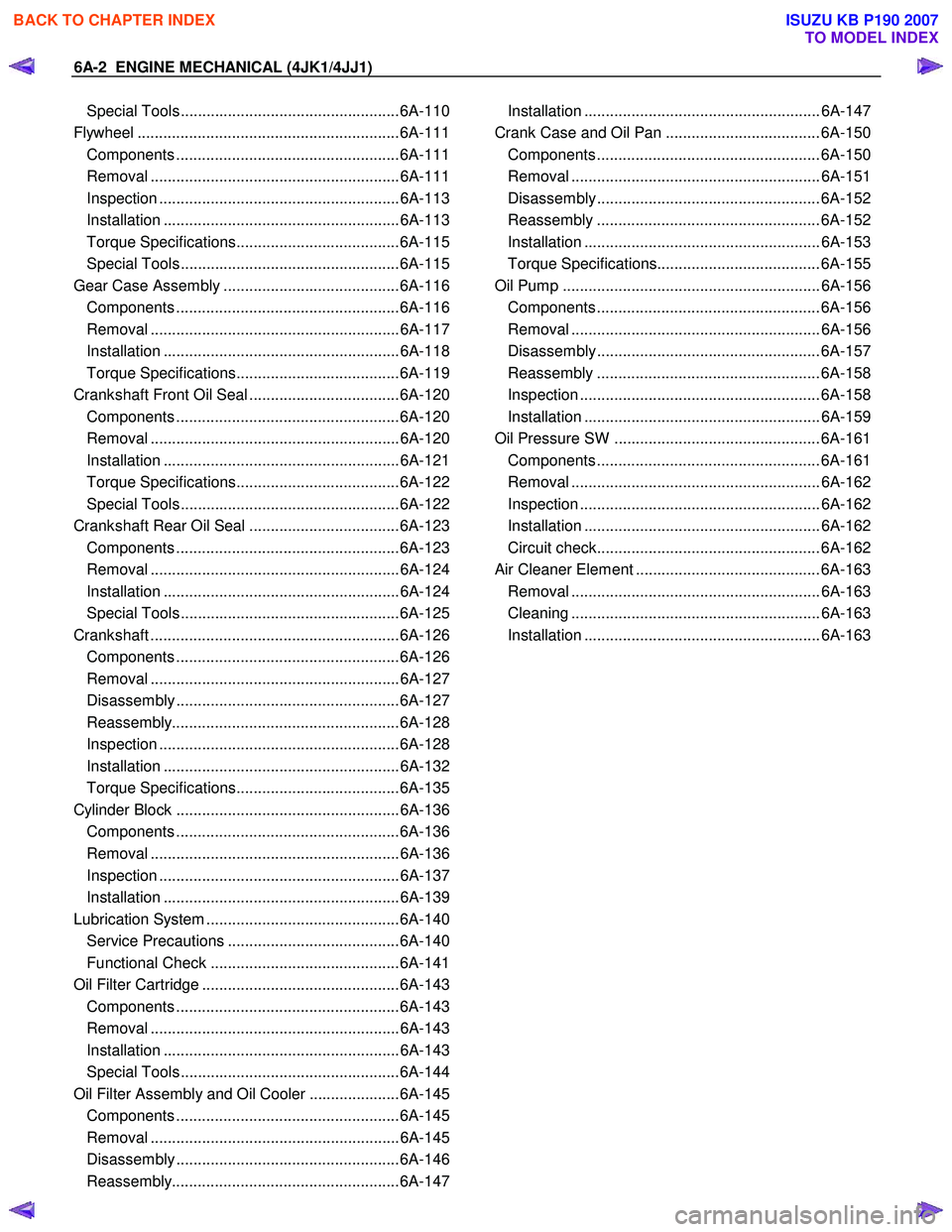
Oil Filter Cartridge ..............................................6A-143 Components ....................................................6A-143
Removal ..........................................................6A-143
Installation .......................................................6A-143
Special Tools ...................................................6A-144
Oil Filter Assembly and Oil Cooler .....................6A-145 Components ....................................................6A-145
Removal ..........................................................6A-145
Disassembly ....................................................6A-146
Reassembly.....................................................6A-147 Installation ....................................................... 6A-147
Crank Case and Oil Pan .................................... 6A-150 Components .................................................... 6A-150
Removal .......................................................... 6A-151
Disassembly .................................................... 6A-152
Reassembly .................................................... 6A-152
Installation ....................................................... 6A-153
Torque Specifications...................................... 6A-155
Oil Pump ............................................................ 6A-156 Components .................................................... 6A-156
Removal .......................................................... 6A-156
Disassembly .................................................... 6A-157
Reassembly .................................................... 6A-158
Inspection ........................................................ 6A-158
Installation ....................................................... 6A-159
Oil Pressure SW ................................................ 6A-161 Components .................................................... 6A-161
Removal .......................................................... 6A-162
Inspection ........................................................ 6A-162
Installation ....................................................... 6A-162
Circuit check.................................................... 6A-162
Air Cleaner Element ........................................... 6A-163 Removal .......................................................... 6A-163
Cleaning .......................................................... 6A-163
Installation ....................................................... 6A-163
BACK TO CHAPTER INDEX
TO MODEL INDEX
ISUZU KB P190 2007
Page 1365 of 6020
ENGINE MECHANICAL (4JK1/4JJ1) 6A-5
EGR system
Based upon data, including water temperature, engine
speeds or engine loads, it is controlled via Engine
Control Module (ECM) to purify exhaust by recycling
part of it.
Its main components include an EGR valve, an EGR
cooler and various sensors.
Connecting rod cap bolt
The angular tightening method of the connecting rod
cap bolt further increases reliability and durability.
Fuel rail-type electronic control injection system
The fuel rail-type electronic control injection system is
composed of a fuel supply pump that sets the target
pressure of high-pressure fuel and supply it, a fuel rail
that measures such high-pressure fuel and a fuel
injector that turns it into a fine spray and injects it. Each
is controlled via ECM based upon various signals, while
injection timing or fuel injection quantity is controlled
under every possible driving condition.
Fuel injector
The fuel injector is a 6-hole nozzle that adjusts fuel
injection quantity or injection timing by opening o
r
closing an electromagnetic valve on the head of the fuel
injector.
ECM corrects the dispersion of fuel injection quantit
y
between fuel injector according to ID code data in
memory. At the replacement of fuel injector, ID code
data should be stored in ECM.
Fuel filter with sedimenter
It is a fuel filter with sedimenter that gets rid of water by
making use of the difference in specific gravity between
light oil and water, which comes with an indicator that
notifies you that it is filled with water.
Preheating system
The preheating system consists of the ECM, the glow
relay, glow plugs and the glow indicator lamp. The
preheating system is operated when the engine coolant
temperature is low, and makes the engine easy to start.
Lubrication system
It is an oil filter with full-flow bypass, which uses a
water-cool oil cooler and oil jet to cool the piston.
Functional inspection
Inspection/adjustment of valve clearance 1. Inspection of valve clearance
• Remove the fuel injector harness assembly.
• Remove the leak off hose.
• Remove the cylinder head cover.
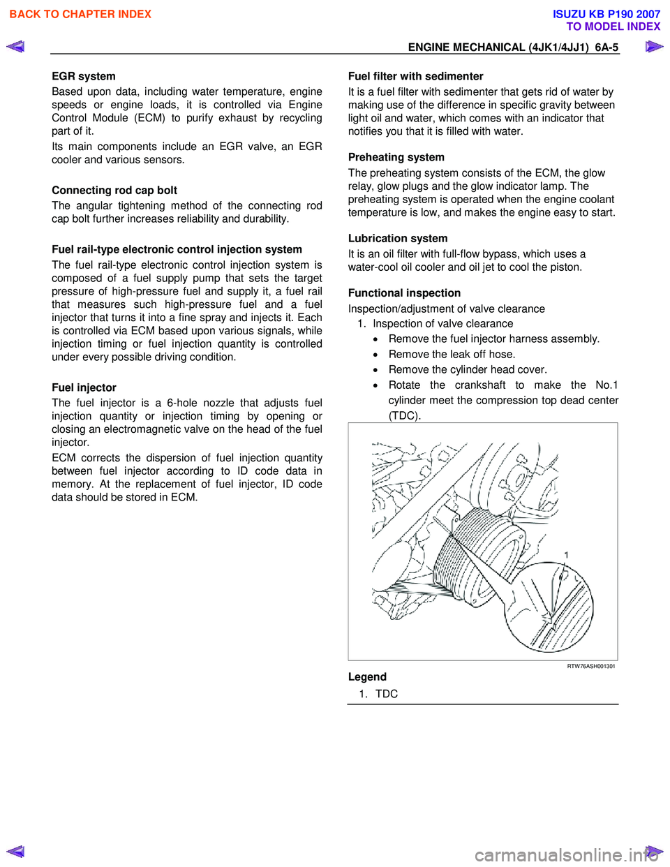
• Rotate the crankshaft to make the No.1
cylinder meet the compression top dead cente
r
(TDC).
RTW 76ASH001301
Legend
1. TDC
BACK TO CHAPTER INDEX
TO MODEL INDEX
ISUZU KB P190 2007
Page 1373 of 6020
ENGINE MECHANICAL (4JK1/4JJ1) 6A-13
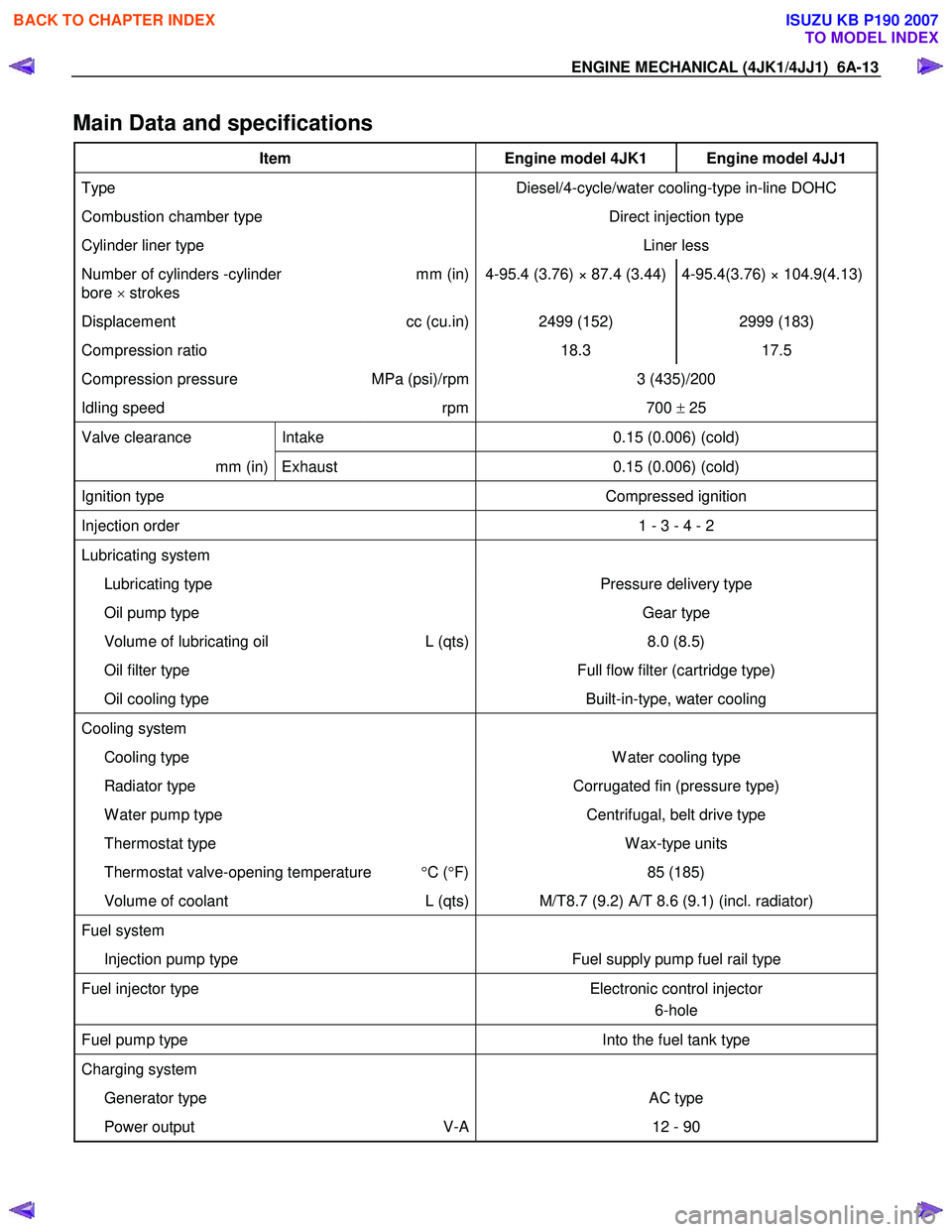
Main Data and specifications
Item Engine model 4JK1 Engine model 4JJ1
Type Diesel/4-cycle/water cooling-type in-line DOHC
Combustion chamber type Direct injection type
Cylinder liner type Liner less
Number of cylinders -cylinder
bore × strokes mm (in) 4-95.4 (3.76) × 87.4 (3.44) 4-95.4(3.76) × 104.9(4.13)
Displacement
cc (cu.in) 2499 (152) 2999 (183)
Compression ratio 18.3 17.5
Compression pressure MPa (psi)/rpm 3 (435)/200
Idling speed rpm 700 ± 25
Valve clearance Intake 0.15 (0.006) (cold)
mm (in) Exhaust 0.15 (0.006) (cold)
Ignition type Compressed ignition
Injection order 1 - 3 - 4 - 2
Lubricating system
Lubricating type Pressure delivery type
Oil pump type Gear type
Volume of lubricating oil L (qts) 8.0 (8.5)
Oil filter type Full flow filter (cartridge type)
Oil cooling type Built-in-type, water cooling
Cooling system
Cooling type W ater cooling type
Radiator type Corrugated fin (pressure type)
W ater pump type Centrifugal, belt drive type
Thermostat type W ax-type units
Thermostat valve-opening temperature °C ( °F) 85 (185)
Volume of coolant L (qts) M/T8.7 (9.2) A/T 8.6 (9.1) (incl. radiator)
Fuel system
Injection pump type Fuel supply pump fuel rail type
Fuel injector type Electronic control injector
6-hole
Fuel pump type Into the fuel tank type
Charging system
Generator type AC type
Power output V-A 12 - 90
BACK TO CHAPTER INDEX
TO MODEL INDEX
ISUZU KB P190 2007
Page 1496 of 6020
6A-136 ENGINE MECHANICAL (4JK1/4JJ1)
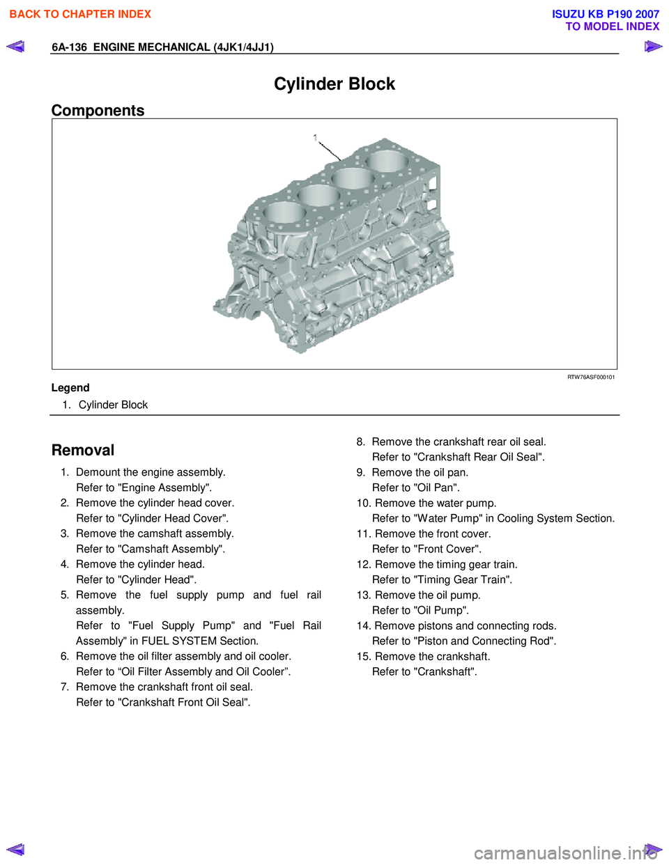
Cylinder Block
Components
RTW 76ASF000101
Legend
1. Cylinder Block
Removal
1. Demount the engine assembly.
Refer to "Engine Assembly".
2. Remove the cylinder head cover.
Refer to "Cylinder Head Cover".
3. Remove the camshaft assembly.
Refer to "Camshaft Assembly".
4. Remove the cylinder head.
Refer to "Cylinder Head".
5. Remove the fuel supply pump and fuel rail assembly.
Refer to "Fuel Supply Pump" and "Fuel Rail Assembly" in FUEL SYSTEM Section.
6. Remove the oil filter assembly and oil cooler.
Refer to “Oil Filter Assembly and Oil Cooler”.
7. Remove the crankshaft front oil seal.
Refer to "Crankshaft Front Oil Seal".
8. Remove the crankshaft rear oil seal.
Refer to "Crankshaft Rear Oil Seal".
9. Remove the oil pan.
Refer to "Oil Pan".
10. Remove the water pump.
Refer to "W ater Pump" in Cooling System Section.
11. Remove the front cover.
Refer to "Front Cover".
12. Remove the timing gear train.
Refer to "Timing Gear Train".
13. Remove the oil pump.
Refer to "Oil Pump".
14. Remove pistons and connecting rods.
Refer to "Piston and Connecting Rod".
15. Remove the crankshaft.
Refer to "Crankshaft".
BACK TO CHAPTER INDEX
TO MODEL INDEX
ISUZU KB P190 2007
Page 1499 of 6020
ENGINE MECHANICAL (4JK1/4JJ1) 6A-139
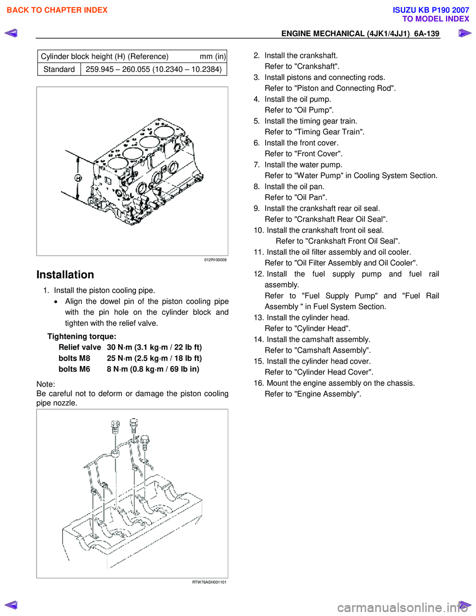
Cylinder block height (H) (Reference) mm (in)
Standard 259.945 – 260.055 (10.2340 – 10.2384)
012R100009
Installation
1. Install the piston cooling pipe.
• Align the dowel pin of the piston cooling pipe
with the pin hole on the cylinder block and
tighten with the relief valve.
Tightening torque: Relief valve 30 N ⋅
⋅⋅
⋅
m (3.1 kg ⋅
⋅⋅
⋅
m / 22 lb ft)
bolts M8 25 N ⋅
⋅⋅
⋅
m (2.5 kg ⋅
⋅⋅
⋅
m / 18 lb ft)
bolts M6 8 N ⋅
⋅⋅
⋅
m (0.8 kg ⋅
⋅⋅
⋅
m / 69 lb in)
Note:
Be careful not to deform or damage the piston cooling
pipe nozzle.
RTW 76ASH001101
2. Install the crankshaft.
Refer to "Crankshaft".
3. Install pistons and connecting rods.
Refer to "Piston and Connecting Rod".
4. Install the oil pump.
Refer to "Oil Pump".
5. Install the timing gear train.
Refer to "Timing Gear Train".
6. Install the front cover.
Refer to "Front Cover".
7. Install the water pump.
Refer to "W ater Pump" in Cooling System Section.
8. Install the oil pan.
Refer to "Oil Pan".
9. Install the crankshaft rear oil seal.
Refer to "Crankshaft Rear Oil Seal".
10. Install the crankshaft front oil seal. Refer to "Crankshaft Front Oil Seal".
11. Install the oil filter assembly and oil cooler.
Refer to "Oil Filter Assembly and Oil Cooler".
12. Install the fuel supply pump and fuel rail assembly.
Refer to "Fuel Supply Pump" and "Fuel Rail Assembly " in Fuel System Section.
13. Install the cylinder head.
Refer to "Cylinder Head".
14. Install the camshaft assembly.
Refer to "Camshaft Assembly".
15. Install the cylinder head cover.
Refer to "Cylinder Head Cover".
16. Mount the engine assembly on the chassis.
Refer to "Engine Assembly".
BACK TO CHAPTER INDEX
TO MODEL INDEX
ISUZU KB P190 2007
Page 1500 of 6020
6A-140 ENGINE MECHANICAL (4JK1/4JJ1)
Lubrication System
Service Precautions
• During each disassembly, remove the old gasket
adhering to each part and mating part completel
y
using a scraper at the location, where the fluid
gasket is to be used, clean the traces of oil,
moisture, and dirt completely using waste cotton
and apply the specified new fluid gasket at each
location.
•
Avoid excessive or insufficient coating volume.
Note that seizure may occur in case of excessive
coating due to clogging of the oil gallery and oil jet,
and oil and water leakage may occur if the coating
is insufficient.
• Always, the start and end of the application should
be overlapped.
Explanations on functions and operation
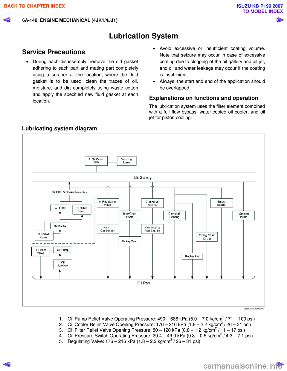
The lubrication system uses the filter element combined
with a full flow bypass, water-cooled oil cooler, and oil
jet for piston cooling.
Lubricating system diagram
LNW 76ALF000201
1. Oil Pump Relief Valve Operating Pressure: 490 – 686 kPa (5.0 – 7.0 kg/cm2 / 71 – 100 psi)
2. Oil Cooler Relief Valve Opening Pressure: 176 – 216 kPa (1.8 – 2.2 kg/cm2 / 26 – 31 psi)
3. Oil Filter Relief Valve Opening Pressure: 80 – 120 kPa (0.8 – 1.2 kg/cm2 / 11 – 17 psi)
4. Oil Pressure Switch Operating Pressure: 29.4 – 49.0 kPa (0.3 – 0.5 kg/cm2 / 4.3 – 7.1 psi)
5. Regulating Valve: 176 – 216 kPa (1.8 – 2.2 kg/cm2 / 26 – 31 psi)
BACK TO CHAPTER INDEX
TO MODEL INDEX
ISUZU KB P190 2007