Page 5712 of 6020

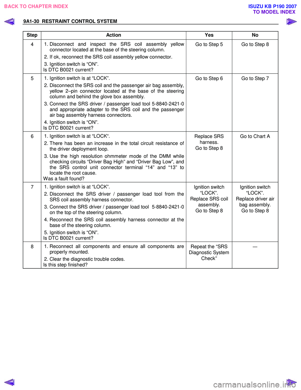
9A1-30 RESTRAINT CONTROL SYSTEM
Step Action Yes No
4
1. Disconnect and inspect the SRS coil assembly yellow
connector located at the base of the steering column.
2. If ok, reconnect the SRS coil assembly yellow connector.
3. Ignition switch is “ON”.
Is DTC B0021 current? Go to Step 5 Go to Step 8
5
1. Ignition switch is at “LOCK”.
2. Disconnect the SRS coil and the passenger air bag assembly,
yellow 2–pin connector located at the base of the steering
column and behind the glove box assembly.
3. Connect the SRS driver / passenger load tool 5-8840-2421-0
and appropriate adapter to the SRS coil and the passenger
air bag assembly harness connectors.
4. Ignition switch is “ON”.
Is DTC B0021 current? Go to Step 6 Go to Step 7
6
1. Ignition switch is at “LOCK“.
2. There has been an increase in the total circuit resistance of
the driver deployment loop.
3. Use the high resolution ohmmeter mode of the DMM while
checking circuits “Driver Bag High” and “Driver Bag Low”, and
the SRS control unit connector terminal “14” and “13” to
locate the root cause.
W as a fault found? Replace SRS
harness.
Go to Step 8 Go to Chart A
7
1. Ignition switch is at “LOCK”.
2. Disconnect the SRS driver / passenger load tool from the
SRS coil assembly harness connector.
3. Connect the SRS driver / passenger load tool 5-8840-2421-0 on the top of the steering column.
4. Reconnect the SRS coil assembly harness connector at the
base of the steering column.
5. Ignition switch is “ON”.
Is DTC B0021 current? Ignition switch
“LOCK”.
Replace SRS coil assembly.
Go to Step 8 Ignition switch
“LOCK”.
Replace driver air bag assembly. Go to Step 8
8
1. Reconnect all components and ensure all components are
properly mounted.
2. Clear the diagnostic trouble codes.
Is this step finished? Repeat the “SRS
Diagnostic System Check” ―
BACK TO CHAPTER INDEX
TO MODEL INDEX
ISUZU KB P190 2007
Page 5715 of 6020

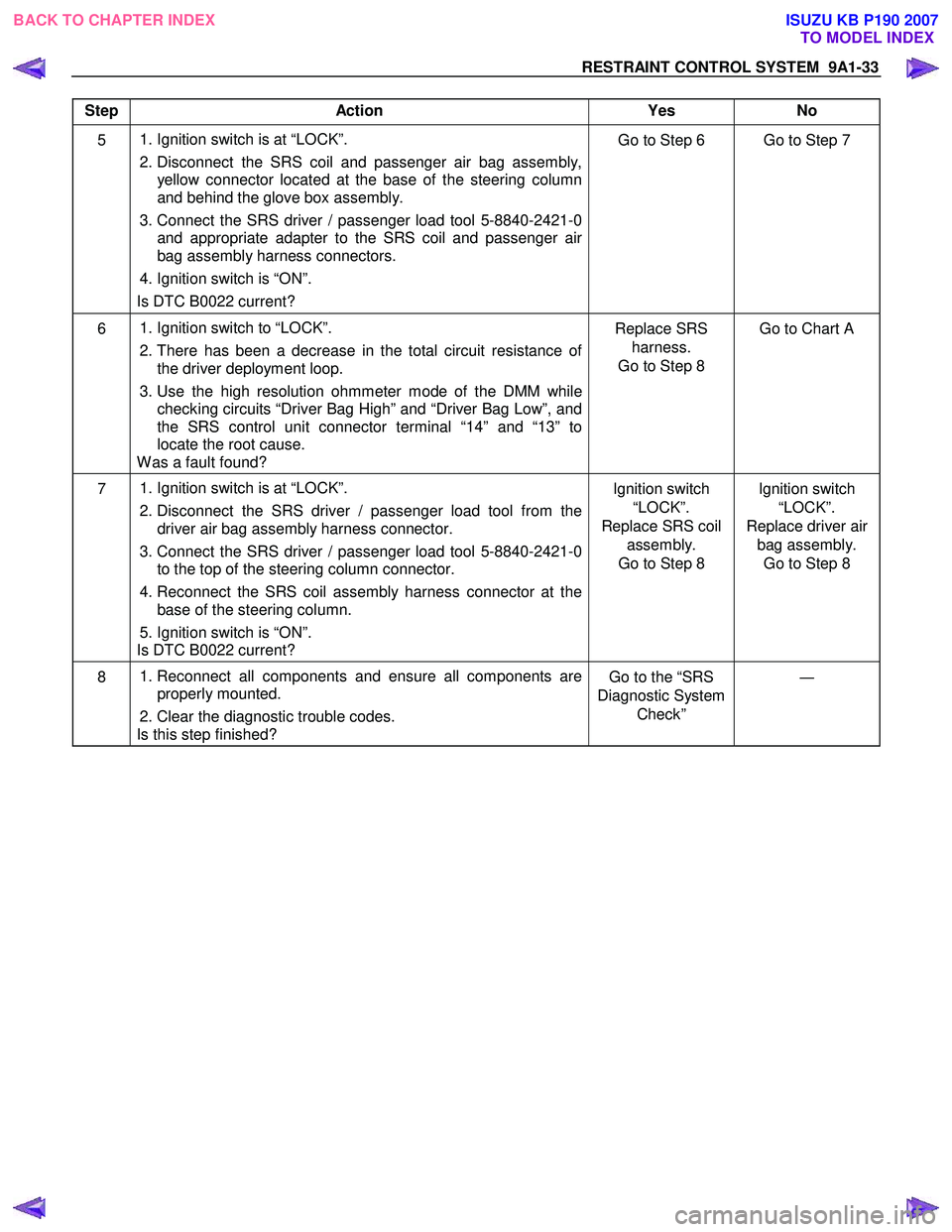
RESTRAINT CONTROL SYSTEM 9A1-33
Step Action Yes No
5 1. Ignition switch is at “LOCK”.
2. Disconnect the SRS coil and passenger air bag assembly, yellow connector located at the base of the steering column
and behind the glove box assembly.
3. Connect the SRS driver / passenger load tool 5-8840-2421-0 and appropriate adapter to the SRS coil and passenger air
bag assembly harness connectors.
4. Ignition switch is “ON”.
Is DTC B0022 current? Go to Step 6 Go to Step 7
6
1. Ignition switch to “LOCK”.
2. There has been a decrease in the total circuit resistance of
the driver deployment loop.
3. Use the high resolution ohmmeter mode of the DMM while
checking circuits “Driver Bag High” and “Driver Bag Low”, and
the SRS control unit connector terminal “14” and “13” to
locate the root cause.
W as a fault found? Replace SRS
harness.
Go to Step 8 Go to Chart A
7
1. Ignition switch is at “LOCK”.
2. Disconnect the SRS driver / passenger load tool from the
driver air bag assembly harness connector.
3. Connect the SRS driver / passenger load tool 5-8840-2421-0 to the top of the steering column connector.
4. Reconnect the SRS coil assembly harness connector at the
base of the steering column.
5. Ignition switch is “ON”.
Is DTC B0022 current? Ignition switch
“LOCK”.
Replace SRS coil assembly.
Go to Step 8 Ignition switch
“LOCK”.
Replace driver air bag assembly. Go to Step 8
8
1. Reconnect all components and ensure all components are
properly mounted.
2. Clear the diagnostic trouble codes.
Is this step finished? Go to the “SRS
Diagnostic System Check” ―
BACK TO CHAPTER INDEX
TO MODEL INDEX
ISUZU KB P190 2007
Page 5785 of 6020
CAB 10-27
INSTRUMENT PANEL
REMOVAL
9
8
2
1
7
4
3
12
2120
15
19
22
18
14
16
13
17
24
23
11
2528
26
24
10
10
27
11
5 6
10
This illustration is based on RHD model RTW 7A0LF001301
Disassembly Steps
▲
1. Front console assembly
▲ 2. Glove box
▲ 3. Instrument panel driver lower cover
assembly
▲ 4. Driver knee bolster assembly
▲ 5. Driver air bag
▲ 6. Steering wheel/ steering cowl
8. Dash side trim cover
9. Front pillar trim cover
10. Front cover
11. Side cover
▲ 12. Instrument panel assembly & Cross
beam
▲ 13. Ashtray case
BACK TO CHAPTER INDEX
TO MODEL INDEX
ISUZU KB P190 2007
Page 5786 of 6020
10-28 CAB
▲ 7. Meter cluster assembly ▲ 14. Center cluster assembly
15. Audio bracket
▲ 16. Control lever assembly
17. Audio assembly
▲ 18. Ashtray bracket
19. Center cluster
20. Meter assembly
21. Passenger lower bracket
22. Glove box cover
▲ 23. Passenger air bag (if so equipped)
▲ 24. Side ventilation grille
▲ 25. Vent duct assembly/Defroster nozzle
assembly
26. Instrument harness assembly
▲ 27. Instrument panel assembly
28. Cross beam
BACK TO CHAPTER INDEX TO MODEL INDEX
ISUZU KB P190 2007
Page 5787 of 6020
CAB 10-29
Important Operations
1. Front Console Assembly • Refer to Floor Consol in this section.
RTW 6A0SH000101
2. Glove Box
• Remove 2 fixing screws and pull on the handle.
RTW 6A0SH000201
3. Instrument Panel Driver Lower Cover Assembly
1) Remove the engine hood opener 2 fixing screws.
2) Remove the lower cover one fixing screw.
3) Pull out the cover (Stick type parking brake only).
4) Pull out the lower cover assembly.
4. Driver Knee Bolster Assembly
• Remove 4 fixing bolts.
Caution:
For precautions on installation or removal of the SRS-air
bag system, refer to section 9 “Supplemental Restraint
System (SRS) - AIR BAG”
5. Driver Air Bag
6. Steering Wheel/Steering Cowl • Refer to Section 3B “STEERING COLUMN” for steering
lock assembly removal steps.
7. Meter Cluster Assembly
• Pull out the 4 clip positions.
BACK TO CHAPTER INDEX TO MODEL INDEX
ISUZU KB P190 2007
Page 5790 of 6020
10-32 CAB
INSTALLATION
18 19
19 19
18
24 231
3
2
20
21
278
22
25
26
17
9
6
5
5
7
28
14
10
11
15
13
16
12
4
This illustration is based on RHD model RTW 7A0LF001401
Installation Steps
1. Cross beam
2. Instrument panel assembly
3. Instrument harness assembly
4. Vent duct assembly/Defroster nozzle assembly
5. Side ventilation grille
6. Passenger air bag
7. Glove box cover
8. Passenger lower bracket
9. Meter assembly
10. Center cluster
11. Ashtray bracket
12. Audio assembly
13. Control lever assembly
14. Audio bracket
15. Center cluster assembly
16. Ashtray case
▲ 17. Instrument panel assembly & Cross
beam
18. Side cover
BACK TO CHAPTER INDEX TO MODEL INDEX
ISUZU KB P190 2007
Page 5791 of 6020
CAB 10-33
19. Front cover
20. Front pillar trim cover
21. Dash side trim cover
22. Meter cluster assembly
▲ 23. Steering wheel/Steering cowl
24. Driver air bag
25. Driver knee bolster assembly
26. Instrument panel driver lower cover assembly
27. Glove box
28. Front console assembly
BACK TO CHAPTER INDEX TO MODEL INDEX
ISUZU KB P190 2007