2007 ISUZU KB P190 front differential
[x] Cancel search: front differentialPage 657 of 6020

5A-64 BRAKE CONTROL SYSTEM
DTC C0238 (Flash Code 38) Front Speed Sensor Correlation
Step Action Value(s) Yes No
1 W ere the steps of the “Basic Diagnostic Flow Chart”
performed?
- Go to Step 2 Go to Basic
Diagnostic
Flow Chart
2 1. Check for the tire size of each wheels.
2. If the tire size is different, replace the tire.
3. If a problem is found, repair as necessary. W as a problem found? - Verify repair Go to Step 3
3 1. Check for the gear ratio of a front axle differential gear and a rear axle differential gear.
2. If the gear ratio is different, repair the gear ratio.
3. If a problem is found, repair as necessary. W as a problem found? - Verify repair Go to Step 4
4 Select “Display DTCs” with the Tech 2.
Note: Perform the various tests (actuator test, test
run, brake test, etc.) then observe the DTC with a
Tech 2.
Are any DTCs stored? - Go to Step 5 Verify repair
5 1. Check for a poor connection at the wheel speed sensor harness connector.
2. Check installation condition for wheel speed sensor.
3. If a problem is found, repair as necessary. W as a problem found? - Verify repair Go to Step 6
6 1. Check condition for sensor rotor.
2. If a problem is found, repair as necessary. W as a problem found? - Verify repair Go to Step 7
7 1. Ignition “OFF” disconnect the EHCU and wheel
speed sensor.
2. Check the circuit between EHCU and wheel speed sensor. (short ground, or short to voltage)
3. If a problem is found, repair as necessary. W as a problem found? - Verify repair Go to Step 8
8 1. Ignition “OFF”.
2. Check the EHCU circuit for an open, short to ground, or short to voltage. Also, check the EHCU
ignition feed circuit for an open or short to ground
and the EHCU ground circuit for an open or short to
voltage.
3. If a problem is found, repair as necessary. W as a problem found? - Verify repair Go to Step 9
9 1. Ignition “ON”, engine “OFF”.
2. Select “Display DTCs” with the Tech 2. Note: Perform the various tests (actuator test, test
run, brake test, etc.) then observe the DTC with a
Tech 2.
Are any DTCs stored? - Go to Step 10 Verify repair
BACK TO CHAPTER INDEX
TO MODEL INDEX
ISUZU KB P190 2007
Page 842 of 6020

ENGINE MECHANICAL 6A – 37
REMOVAL AND INSTALLATION
Read this section carefully before performing any removal and installation procedure. This section gives
you important points as well as the order of operation. Be sure that you understand everything in this section before
you begin.
Removal
P1010011
1. Battery
1) Disconnect the battery cable and the grounding cable from the battery terminals.
2) Remove the battery clamp. Take care not to accidentally short the battery with the wrench or some
other tool.
3) Remove the battery.
4) Disconnect the battery cable at the starter motor and the ground cable at the cylinder body.
2. Engine Hood Apply setting marks to the engine hood and the engine
hood hinges before removing the engine hood. This will
facilitate reinstallation of the engine hood to its original
position.
3. Supporting the Vehicle 1) Jack up the vehicle.
2) Place chassis stands at the front and the rear of the vehicle.
4. Under cover (for 4x4 model) 5. Rear propeller shaft 1) Remove the propeller shaft flange yoke at the rear differential.
2) Remove the center bearing retainer bolts.
3) Remove the propeller shaft together with the center bearing from the transmission mainshaft spline.
F06R300006 P1010002
BACK TO CHAPTER INDEX
TO MODEL INDEX
ISUZU KB P190 2007
Page 4125 of 6020
7A3-40 ON-VEHICLE SERVICE (AW30–40LE)
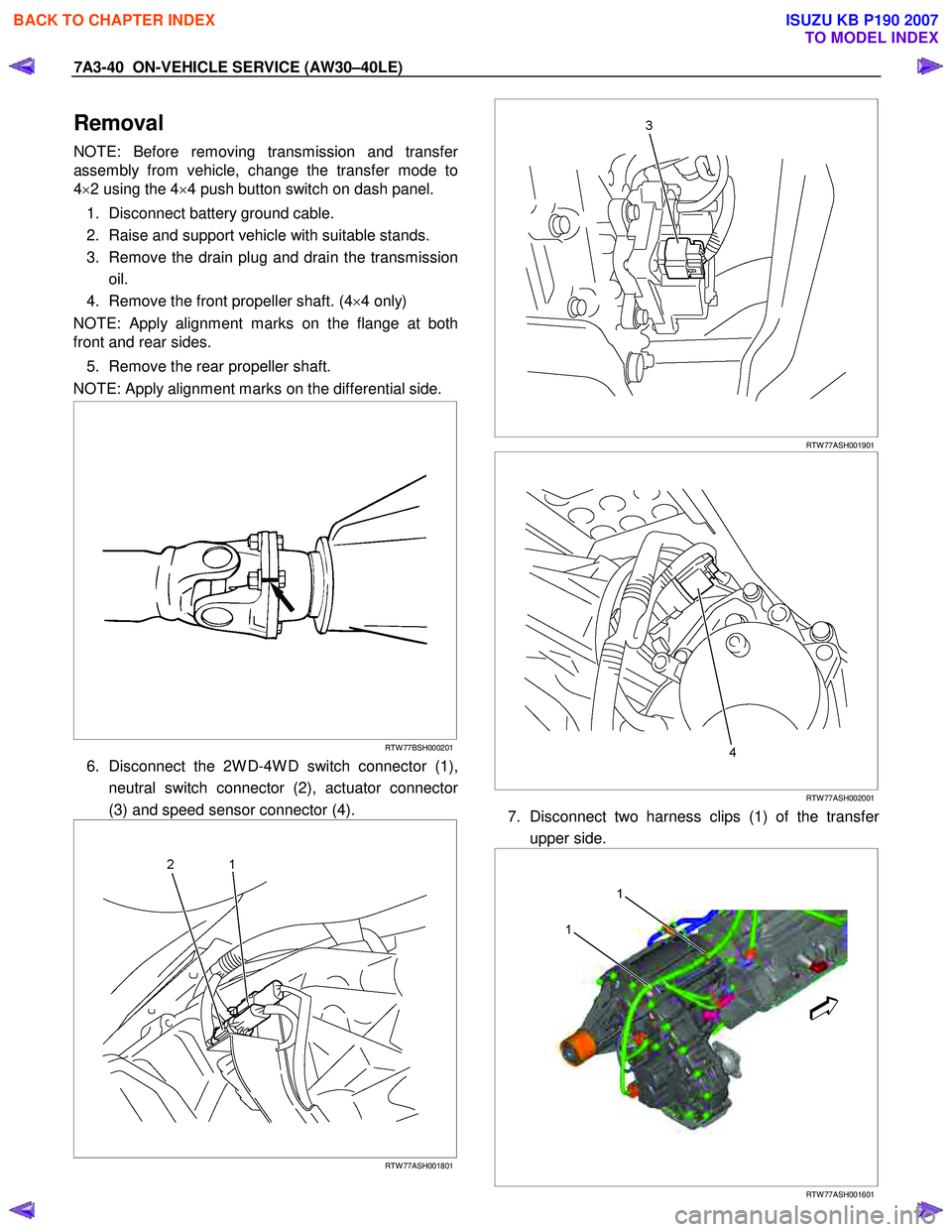
Removal
NOTE: Before removing transmission and transfer
assembly from vehicle, change the transfer mode to
4 ×2 using the 4 ×4 push button switch on dash panel.
1. Disconnect battery ground cable.
2. Raise and support vehicle with suitable stands.
3. Remove the drain plug and drain the transmission oil.
4. Remove the front propeller shaft. (4 ×4 only)
NOTE: Apply alignment marks on the flange at both
front and rear sides.
5. Remove the rear propeller shaft.
NOTE: Apply alignment marks on the differential side.
RTW 77BSH000201
6. Disconnect the 2W D-4W D switch connector (1),
neutral switch connector (2), actuator connecto
r
(3) and speed sensor connector (4).
RTW 77ASH001801
RTW 77ASH001901
RTW 77ASH002001
7. Disconnect two harness clips (1) of the transfer
upper side.
1
1
RTW 77ASH001601
BACK TO CHAPTER INDEX
TO MODEL INDEX
ISUZU KB P190 2007
Page 4615 of 6020
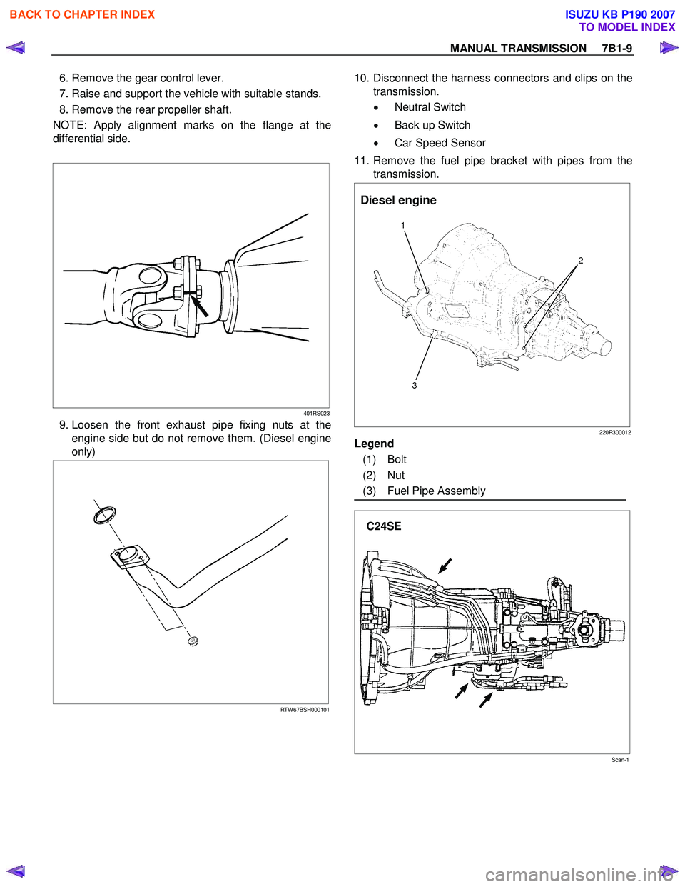
MANUAL TRANSMISSION 7B1-9
6. Remove the gear control lever.
7. Raise and support the vehicle with suitable stands.
8. Remove the rear propeller shaft.
NOTE: Apply alignment marks on the flange at the
differential side.
401RS023
9. Loosen the front exhaust pipe fixing nuts at the engine side but do not remove them. (Diesel engine
only)
RTW 67BSH000101
10. Disconnect the harness connectors and clips on the
transmission.
• Neutral Switch
• Back up Switch
• Car Speed Sensor
11. Remove the fuel pipe bracket with pipes from the transmission.
Diesel engine
220R300012
Legend
(1) Bolt
(2) Nut
(3) Fuel Pipe Assembly
C24SE
Scan-1
BACK TO CHAPTER INDEX
TO MODEL INDEX
ISUZU KB P190 2007
Page 4669 of 6020
MANUAL TRANSMISSION 7B1-63
6. Remove the gear control lever.
7. Raise and support the vehicle with suitable stands.
8. Remove the rear propeller shaft.
NOTE: Apply alignment marks on the flange at the
differential side.
9. Remove the front propeller shaft.
NOTE:
Apply alignment marks on the flange at both
front and rear sides.
401RS023
10. Loosen the front exhaust pipe fixing nuts at the engine side but do not remove them. (Diesel engine
only)
RTW 67BSH000101
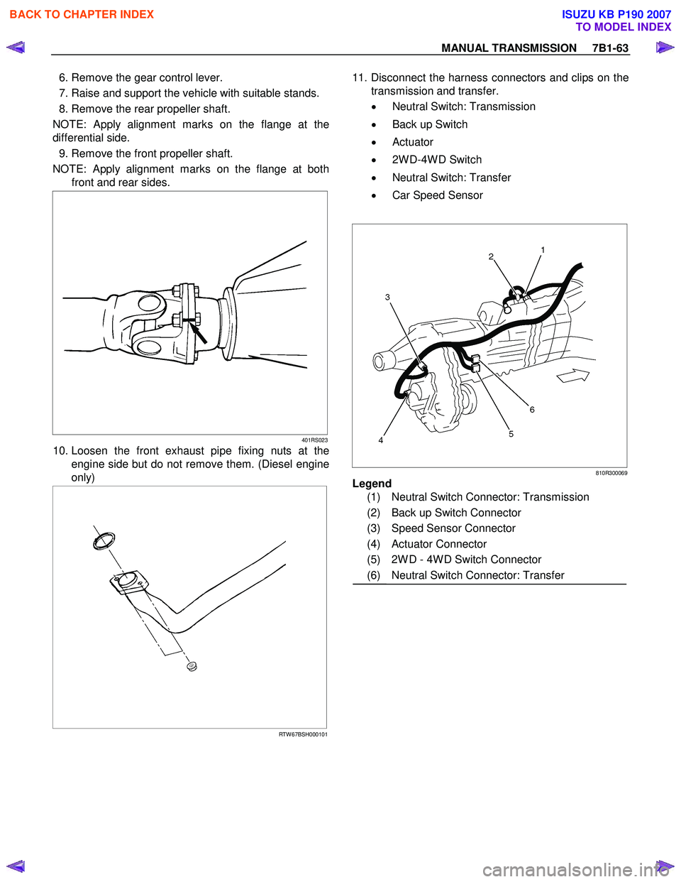
11. Disconnect the harness connectors and clips on the
transmission and transfer.
• Neutral Switch: Transmission
• Back up Switch
• Actuator
• 2W D-4W D Switch
• Neutral Switch: Transfer
• Car Speed Sensor
810R300069
Legend
(1) Neutral Switch Connector: Transmission
(2) Back up Switch Connector
(3) Speed Sensor Connector
(4) Actuator Connector
(5) 2W D - 4W D Switch Connector
(6) Neutral Switch Connector: Transfer
BACK TO CHAPTER INDEX
TO MODEL INDEX
ISUZU KB P190 2007
Page 4728 of 6020
Manual Transmission (MUX) 7B1-9
• Apply alignment marks on the flange at thedifferential side.
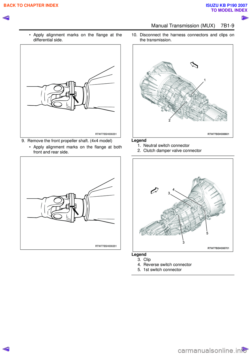
9. Remove the front propeller shaft. (4x4 model) • Apply alignment marks on the flange at bothfront and rear side. 10. Disconnect the harness connectors and clips on
the transmission.
Legend 1. Neutral switch connector
2. Clutch damper valve connector
Legend 3. Clip
4. Reverse switch connector
5. 1st switch connector
RTW77BSH000201
RTW77BSH000201
RTW77BSH006601
1
2
RTW77BSH006701
3
3 54
BACK TO CHAPTER INDEX
TO MODEL INDEX
ISUZU KB P190 2007
Page 4920 of 6020
7D1-46 TRANSFER CONTROL SYSTEM
Diagnosis
Before determining a trouble (Non-trouble mode)
1. When shifting from 2H to 4H:
1-1-1 When the flashing frequency of the 4WD indicator is changed from 2Hz to 4Hz (Shift on the fly) If the load is too large to shift the gears synchronously, the operation is repeated up to 3 times. If the shifting
is not effected after being repeated 3 times, the indicator frequency is changed from 2Hz to 4Hz. At the same
time, the actuator condition is changed to 2H, indicator flashes at 4Hz for 10 seconds, and then goes out.
Cause of excessive synchronous shifting load
• Extremely low temperature (the oil viscosity of the front differential increases requiring a large load for
synchronization).
• High speed (since the difference of relative revolutions of gears to be shifted synchronously is too large,
required work load per unit time becomes larger).
Step 1-1-1:
Stop the vehicle or decrease the speed and operate as required again.
1-1-2 When the flashing frequency of the 4WD indicator is changed from 2Hz to 4Hz (Rigid and free wheel
Hub) / Block out of meshing spline in transfer case.
Step 1-1-2:
Run the vehicle forward and backward several meters and operate as required again.
1-2 When the flashing of 4WD indicator at 2Hz continues more than 11.5 seconds (repetition of 3 times of
above No.1 is counted) (Shift on the fly)
If there is difference of revolutions and phases between the front wheel and the axle, connecting the front
wheel and axle is difficult.
Until shifting in the transfer and connection of the front wheel and axle are completed
∗, the indicator flashes at
a frequency of 2Hz. In the above case, the indicator continues flashing at a frequency of 2Hz until the
connection of the front axle is completed. (If the shifting in the transfer is not completed, the flashing
frequency is changed to 4Hz (above No.1).)
By correcting the difference of relative revolutions and deviation of phases, the shifting can be completed.
Step 1-2:
While the vehicle is running, check it is safe around the vehicle and then accelerate or decelerate the
vehicle while going straight.
When the vehicle is at a stop, run the vehicle forward and backward several meters.
2. When shifting from 4H to 2H
2-1 When 4WD indicator continues flashing at 2Hz
W hen shifting from 4H to 2H, the 4W D indicator continues flashing at 2Hz until separation in the transfer and
the separation of the front wheel axle are completed∗. W hen torsional torque is accumulated in the drive
system, separation in the transfer and separation of the front axle∗ is difficult. In such a case, they can be
separated by removing the torsional torque of the drive system.
Step 2-1:
While the vehicle is running, check it is safe around the vehicle and then accelerate or decelerate the
vehicle while going straight.
When the vehicle is in stop, run the vehicle several meters forward and backward.
∗: Shift on the fly only.
BACK TO CHAPTER INDEX
TO MODEL INDEX
ISUZU KB P190 2007