Page 2883 of 6020
Engine Mechanical – V6 Page 6A1–106
Page 6A1–106
3 Remove the coolant pump seal (1) from the engine
front cover (2). Discard the seal.
Figure 6A1 – 88
Clean
4 Remove any RTV sealant (1) from the engine front cover using a plastic or wood scraper.
CAUTION
• Insert a piece of cardboard between the
front of the oil pan and oil pump to
prevent any contaminants from falling
into the oil pan.
• Do not use a sharp or metal gasket
scraper to clean the sealing surfaces.
5 Clean out any debris from the bolt holes.
6 Clean the front cover with a suitable cleaning solvent.
7 Dry the front cover with compressed air.
Safety glasses must be worn when using
compressed air.
Figure 6A1 – 89
8 Use compressed air to remove any engine coolant from the engine cooling passages and from the top of the oil
pan oil deflector.
BACK TO CHAPTER INDEX
TO MODEL INDEX
ISUZU KB P190 2007
Page 2884 of 6020

Engine Mechanical – V6 Page 6A1–107
Page 6A1–107
Inspect
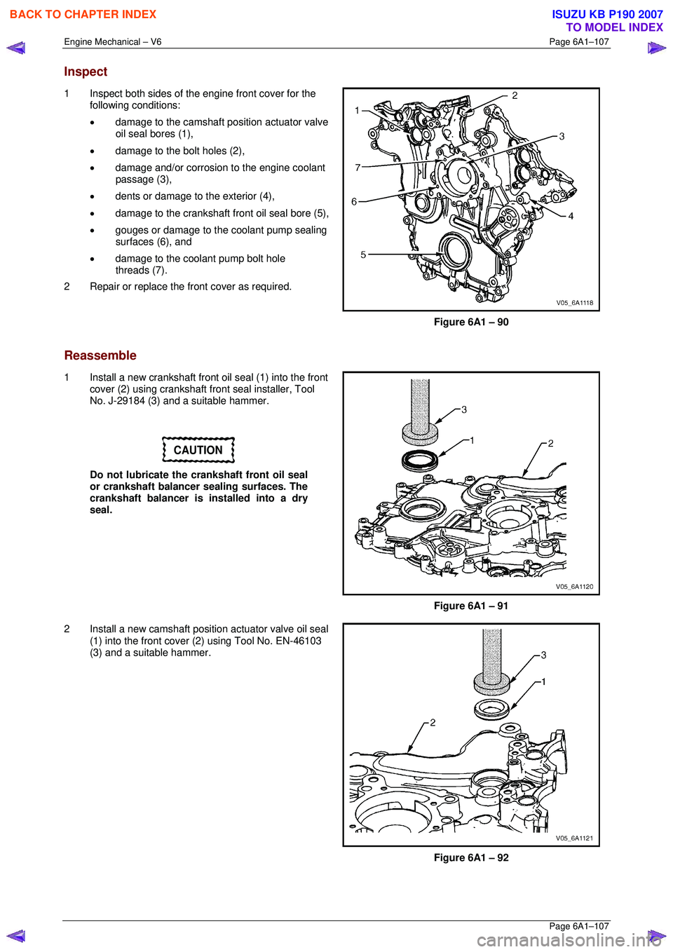
1 Inspect both sides of the engine front cover for the
following conditions:
• damage to the camshaft position actuator valve
oil seal bores (1),
• damage to the bolt holes (2),
• damage and/or corrosion to the engine coolant
passage (3),
• dents or damage to the exterior (4),
• damage to the crankshaft front oil seal bore (5),
• gouges or damage to the coolant pump sealing
surfaces (6), and
• damage to the coolant pump bolt hole
threads (7).
2 Repair or replace the fr ont cover as required.
Figure 6A1 – 90
Reassemble
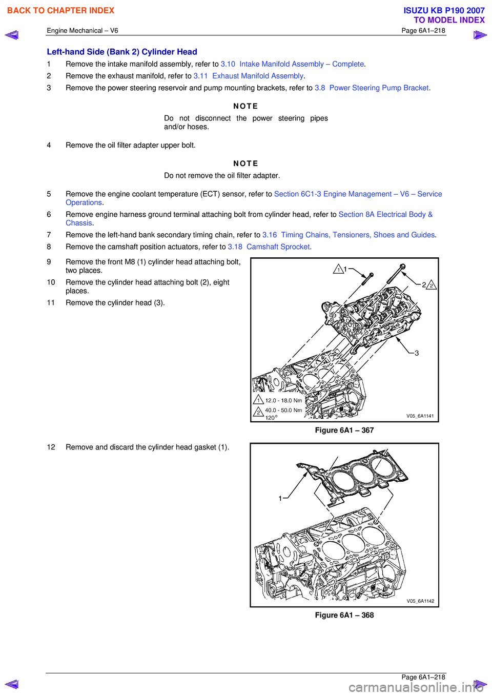
1 Install a new crankshaft front oil seal (1) into the front cover (2) using crankshaft front seal installer, Tool
No. J-29184 (3) and a suitable hammer.
CAUTION
Do not lubricate the crankshaft front oil seal
or crankshaft balancer sealing surfaces. The
crankshaft balancer is installed into a dry
seal.
Figure 6A1 – 91
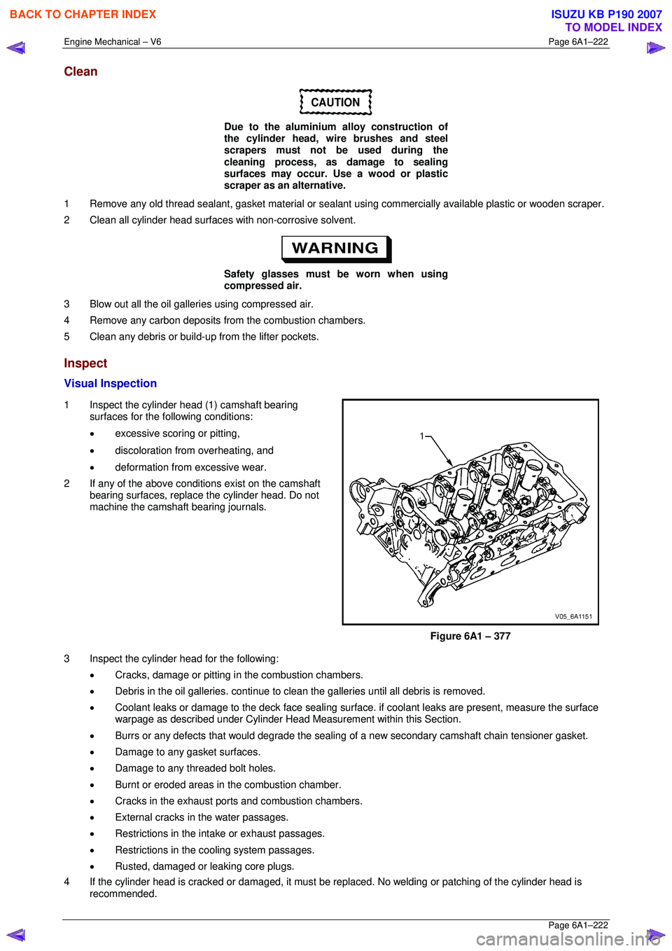
2 Install a new camshaft positi on actuator valve oil seal
(1) into the front cover (2) using Tool No. EN-46103
(3) and a suitable hammer.
Figure 6A1 – 92
BACK TO CHAPTER INDEX
TO MODEL INDEX
ISUZU KB P190 2007
Page 2995 of 6020

Engine Mechanical – V6 Page 6A1–218
Page 6A1–218
Left-hand Side (Bank 2) Cylinder Head
1 Remove the intake manifold assembly, refer to 3.10 Intake Manifold Assembly – Complete .
2 Remove the exhaust manifold, refer to 3.11 Exhaust Manifold Assembly.
3 Remove the power steering reservoi r and pump mounting brackets, refer to 3.8 Power Steering Pump Bracket.
NOTE
Do not disconnect the power steering pipes
and/or hoses.
4 Remove the oil filter adapter upper bolt. NOTE
Do not remove the oil filter adapter.
5 Remove the engine coolant temper ature (ECT) sensor, refer to Section 6C1-3 Engine Management – V6 – Service
Operations .
6 Remove engine harness ground terminal attach ing bolt from cylinder head, refer to Section 8A Electrical Body &
Chassis .
7 Remove the left-hand bank secondary timing chain, refer to 3.16 Timing Chains, Tensioners, Shoes and Guides.
8 Remove the camshaft position actuators, refer to 3.18 Camshaft Sprocket.
9 Remove the front M8 (1) cylinder head attaching bolt, two places.
10 Remove the cylinder head attaching bolt (2), eight places.
11 Remove the cylinder head (3).
Figure 6A1 – 367
12 Remove and discard the cylinder head gasket (1).
Figure 6A1 – 368
BACK TO CHAPTER INDEX
TO MODEL INDEX
ISUZU KB P190 2007
Page 2998 of 6020
Engine Mechanical – V6 Page 6A1–221
Page 6A1–221
CAUTION
Never reuse a valve stem oil seal.
8 Remove the valve stem oil seal using Tool No. EN-46116 and discard.
9 Repeat these procedures for the remaining valves.
Figure 6A1 – 374
10 Remove the cylinder head oil gallery expansion plugs (1).
Figure 6A1 – 375
11 Remove the cylinder head coolant threaded plugs (1).
Figure 6A1 – 376
BACK TO CHAPTER INDEX
TO MODEL INDEX
ISUZU KB P190 2007
Page 2999 of 6020

Engine Mechanical – V6 Page 6A1–222
Page 6A1–222
Clean
CAUTION
Due to the aluminium alloy construction of
the cylinder head, wire brushes and steel
scrapers must not be used during the
cleaning process, as damage to sealing
surfaces may occur. Use a wood or plastic
scraper as an alternative.
1 Remove any old thread sealant, gasket material or seal ant using commercially available plastic or wooden scraper.
2 Clean all cylinder head surfaces with non-corrosive solvent.
Safety glasses must be worn when using
compressed air.
3 Blow out all the oil galleries using compressed air.
4 Remove any carbon deposits fr om the combustion chambers.
5 Clean any debris or build-up from the lifter pockets.
Inspect
Visual Inspection
1 Inspect the cylinder head (1) camshaft bearing surfaces for the following conditions:
• excessive scoring or pitting,
• discoloration from overheating, and
• deformation from excessive wear.
2 If any of the above conditions exist on the camshaft bearing surfaces, replace the cylinder head. Do not
machine the camshaft bearing journals.
Figure 6A1 – 377
3 Inspect the cylinder head for the following: • Cracks, damage or pitting in the combustion chambers.
• Debris in the oil galleries. continue to cl ean the galleries until all debris is removed.
• Coolant leaks or damage to the deck face sealing surfac e. if coolant leaks are present, measure the surface
warpage as described under Cylinder Head M easurement within this Section.
• Burrs or any defects that would degrade the sealing of a new secondar y camshaft chain tensioner gasket.
• Damage to any gasket surfaces.
• Damage to any threaded bolt holes.
• Burnt or eroded areas in the combustion chamber.
• Cracks in the exhaust ports and combustion chambers.
• External cracks in the water passages.
• Restrictions in the intake or exhaust passages.
• Restrictions in the cooling system passages.
• Rusted, damaged or leaking core plugs.
4 If the cylinder head is cracked or damaged, it must be r eplaced. No welding or patching of the cylinder head is
recommended.
BACK TO CHAPTER INDEX
TO MODEL INDEX
ISUZU KB P190 2007
Page 3007 of 6020
Engine Mechanical – V6 Page 6A1–230
Page 6A1–230
Assemble
1 Install the cylinder head coolant threaded plugs (1)
and tighten to the correct torque specification.
Cylinder head thre aded plug .............................. 31.0 Nm
Figure 6A1 – 388
2 Install the cylinder head oil gallery expansion plugs (1).
Figure 6A1 – 389
CAUTION
• Never reuse a valve stem oil seal. Always
use new seals when assembling the
cylinder head.
• Force should only be applied to the valve
spring contact area of the new valve stem
oil seal during installation.
3 Fit the valve stem oil seal s onto the guides using Tool
No. EN-46116 (1).
4 Push and twist the valve stem oil seal into position on the valve guide until the s eal positively locks on the
guide using Tool No. EN-46116.
5 Lubricate the valve stem and valve guide ID with clean engine oil.
Figure 6A1 – 390
BACK TO CHAPTER INDEX
TO MODEL INDEX
ISUZU KB P190 2007
Page 3017 of 6020
Engine Mechanical – V6 Page 6A1–240
Page 6A1–240
Remove
1 Remove the skid plate.
2 Drain the radiator coolant, refer to Section 6B1 Engine Cooling – V6.
3 Disconnect the battery negative and positive terminal, refer to Section 8A Electrical Body & Chassis.
4 Remove the battery from the vehicle.
5 Depressurise the fuel sy stem pressure, refer to Section 6C Fuel System – V6 .
6 Make alignment marks on the bonnet and hinges in order to return the bonnet to the exact original position.
7 Remove the bonnet, refer to Section 2B Sheet Metal.
8 Remove the rubber hose (2) and air duct (1).
Figure 6A1 – 407
9 Disconnect the barometric sensor connector (1).
Figure 6A1 – 408
BACK TO CHAPTER INDEX
TO MODEL INDEX
ISUZU KB P190 2007
Page 3026 of 6020
Engine Mechanical – V6 Page 6A1–249
Page 6A1–249
54 Remove the power steering pump bracket mounting
bolts (three places) then remove the pump bracket
(1).
Figure 6A1 – 432
55 Release the lower radiator hose clamp (1) and remove the lower hose from the coolant pipe (2).
Figure 6A1 – 433
56 Release the upper radiator hose clamp (1) and remove the upper hose from the coolant pipe (2).
Figure 6A1 – 434
BACK TO CHAPTER INDEX
TO MODEL INDEX
ISUZU KB P190 2007