2007 ISUZU KB P190 engine coolant
[x] Cancel search: engine coolantPage 2837 of 6020
Engine Mechanical – V6 Page 6A1–60
Page 6A1–60
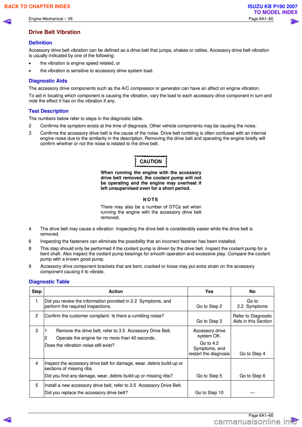
Drive Belt Vibration
Definition
Accessory drive belt vibration can be defined as a drive belt that jumps, shakes or rattles. Accessory drive belt vibration
is usually indicated by one of the following:
• the vibration is engine speed related, or
• the vibration is sensitive to accessory drive system load.
Diagnostic Aids
The accessory drive components such as the A/C compre ssor or generator can have an affect on engine vibration.
To aid in locating which component is causing the vibration, vary the load to each accessory drive component in turn and
note the effect it has on the vibration if any.
Test Description
The numbers below refer to steps in the diagnostic table.
2 Confirms the symptom exists at the time of di agnosis. Other vehicle components may be causing the noise.
3 Confirms the accessory drive belt is the cause of the noise. Drive belt rumbling is often confused with an internal
engine noise due to the similarity in the description. Removing the drive belt and operating the engine briefly will
confirm whether or not the noise is related to the drive belt.
CAUTION
When running the engine with the accessory
drive belt removed, the coolant pump will not
be operating and the engine may overheat if
left unsupervised even for a short period.
NOTE
There may also be a number of DTCs set when
running the engine with the accessory drive belt
removed.
4 The drive belt may cause a vibration. Inspecting the drive belt is considerably easier while the drive belt is
removed.
6 Inspecting the fasteners can eliminate the possibility that an inco rrect fastener has been installed.
8 This step should only be performed if t he coolant pump is driven by the drive belt. Inspect the coolant pump for a
bent shaft. Also inspect the coolant pump bearings for smooth operation and excessive play. Compare the coolant
pump with a known good pump.
9 Accessory drive component brackets that are bent, cra cked or loose may put extra strain on the accessory
component causing it to vibrate.
Diagnostic Table
Step Action Yes No
1
Did you review the information provided in 2.2 Symptoms, and
perform the required inspections. Go to Step 2 Go to
2.2 Symptoms
2 Confirm the customer compla int. Is there a rumbling noise?
Go to Step 3 Refer to Diagnostic
Aids in this Section
3 1 Remove the drive belt, refer to 3.5 Accessory Drive Belt.
2 Operate the engine for no more than 40 seconds.
Does the vibration noise still exist? Accessory drive
system OK.
Go to 4.2
Symptoms, and
restart the diagnosis Go to Step 4
4 Inspect the accessory drive belt for damage, wear, debris build-up or
sections of missing ribs.
Did you find any damage, wear, debris build-up or missing ribs? Go to Step 5 Go to Step 6
5 Install a new accessory drive belt, refer to 3.5 Accessory Drive Belt.
Did you replace the accessory drive belt? Go to Step 10 —
BACK TO CHAPTER INDEX
TO MODEL INDEX
ISUZU KB P190 2007
Page 2838 of 6020
Engine Mechanical – V6 Page 6A1–61
Page 6A1–61
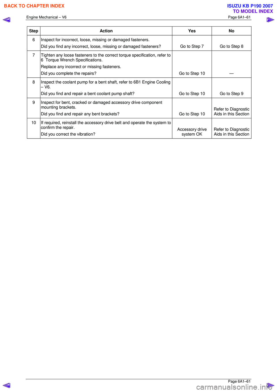
Step Action Yes No
6 Inspect for incorrect, loose, missing or damaged fasteners.
Did you find any incorrect, loose, missing or damaged fasteners? Go to Step 7 Go to Step 8
7
Tighten any loose fasteners to the corre ct torque specification, refer to
6 Torque Wrench Specifications.
Replace any incorrect or missing fasteners.
Did you complete the repairs? Go to Step 10 —
8
Inspect the coolant pump for a bent shaft, refer to 6B1 Engine Cooling
– V6.
Did you find and repair a bent coolant pump shaft? Go to Step 10 Go to Step 9
9
Inspect for bent, cracked or damaged accessory drive component
mounting brackets.
Did you find and repair any bent brackets? Go to Step 10 Refer to Diagnostic
Aids in this Section
10 If required, reinstall the accessory drive belt and operate the system to
confirm the repair.
Did you correct the vibration? Accessory drive
system OK Refer to Diagnostic
Aids in this Section
BACK TO CHAPTER INDEX
TO MODEL INDEX
ISUZU KB P190 2007
Page 2849 of 6020
Engine Mechanical – V6 Page 6A1–72
Page 6A1–72
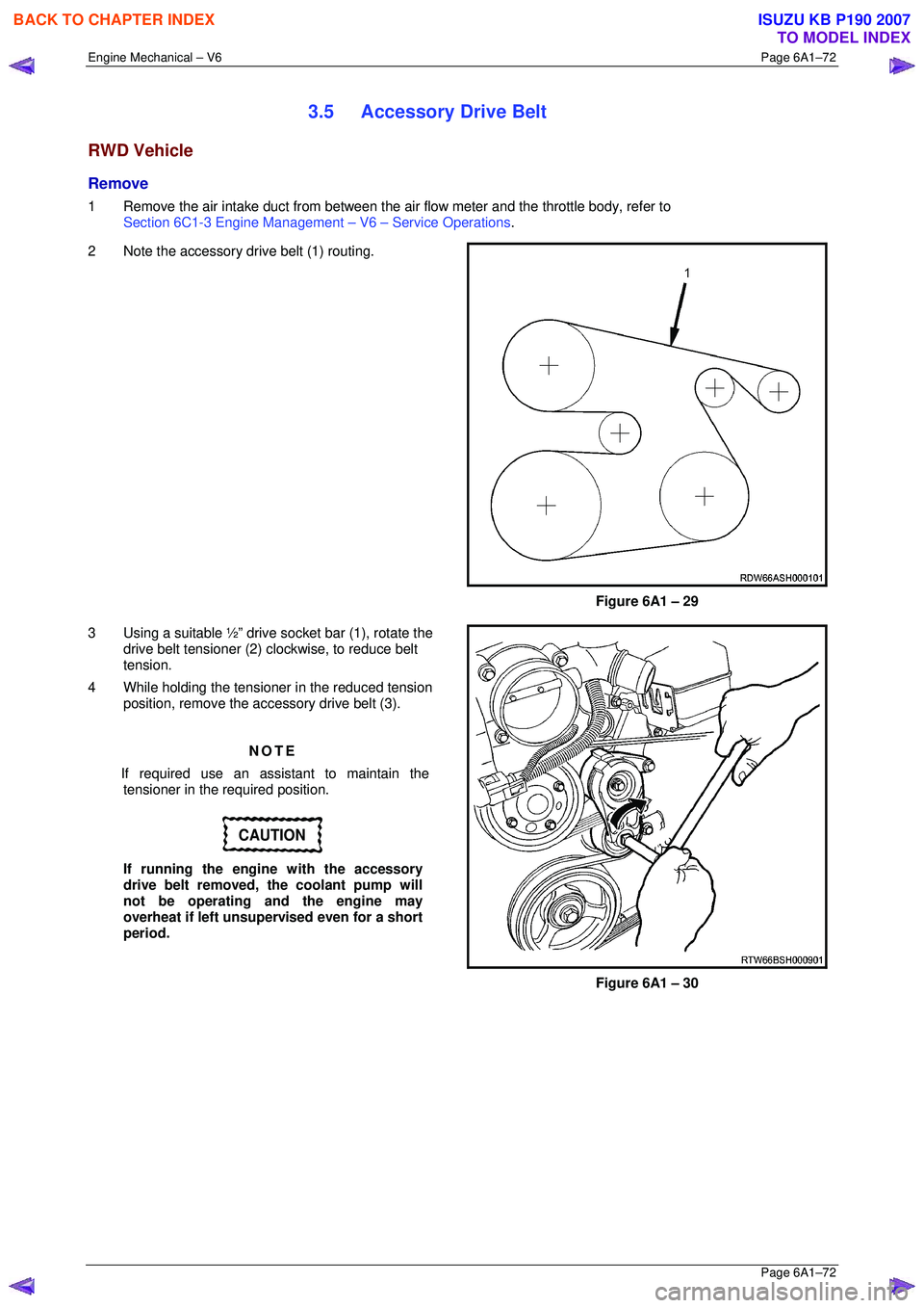
3.5 Accessory Drive Belt
RWD Vehicle
Remove
1 Remove the air intake duct from between the air flow meter and the throttle body, refer to
Section 6C1-3 Engine Management – V6 – Service Operations.
2 Note the accessory drive belt (1) routing.
Figure 6A1 – 29
3 Using a suitable ½” drive socket bar (1), rotate the drive belt tensioner (2) clockwise, to reduce belt
tension.
4 While holding the tensioner in the reduced tension
position, remove the accessory drive belt (3).
NOTE
If required use an assistant to maintain the tensioner in the required position.
CAUTION
If running the engine with the accessory
drive belt removed, the coolant pump will
not be operating and the engine may
overheat if left unsupervised even for a short
period.
Figure 6A1 – 30
BACK TO CHAPTER INDEX
TO MODEL INDEX
ISUZU KB P190 2007
Page 2850 of 6020
Engine Mechanical – V6 Page 6A1–73
Page 6A1–73
Reinstall
1 Install the drive belt over the A/C compressor, idler pulley, power steering pump, coolant pump, generator and
tensioner pulleys.
2 Using a suitable ½” drive socket bar (1), rotate the driv e belt tensioner (2) clockwise, refer to Figure 6A1 – 30.
3 With an assistant holding the tensi oner in the required position, feed the accessory drive belt (3) over the
crankshaft pulley.
4 Slowly release the drive belt tensioner mechanism.
NOTE
Ensure the drive belt ribs are correctly aligned
with the grooves in the accessory drive pulleys or
damage to the drive belt and accessory drive
components and pulleys may occur.
5 Reinstall the air intake duct to the ai r flow meter and the throttle body, refer to Section 6C1-3 Engine Management
– V6 – Service Operations .
6 Run the engine to ensure correct operation.
BACK TO CHAPTER INDEX
TO MODEL INDEX
ISUZU KB P190 2007
Page 2869 of 6020

Engine Mechanical – V6 Page 6A1–92
Page 6A1–92
9 Progressively loosen the seven exhaust manifold
attaching bolts (2), working from the outside to the
centre and then remove the bolts.
10 Manoeuvre the exhaust manifold (3), away from the cylinder head.
11 Remove and discard the exhaust manifold to cylinder head gasket.
Figure 6A1 – 58
12 Remove the three bolts (1), attaching the exhaust manifold inner heat shield to the exhaust manifold.
13 Using a suitable commercially available non-corrosive cleaning solvent and a soft bristled parts cleaning
brush, thoroughly clean the exhaust manifold.
14 Dry the exhaust manifold using compressed air.
Safety glasses must be worn when using
compressed air.
Figure 6A1 – 59
NOTE
• The same procedure applies to the Right-
hand exhaust manifold.
• To gain access to the lower rear exhaust
manifold attaching bolts (2), apply a slight
downward movement to the coolant inlet
pipe (1).
BACK TO CHAPTER INDEX
TO MODEL INDEX
ISUZU KB P190 2007
Page 2870 of 6020
Engine Mechanical – V6 Page 6A1–93
Page 6A1–93
Inspect
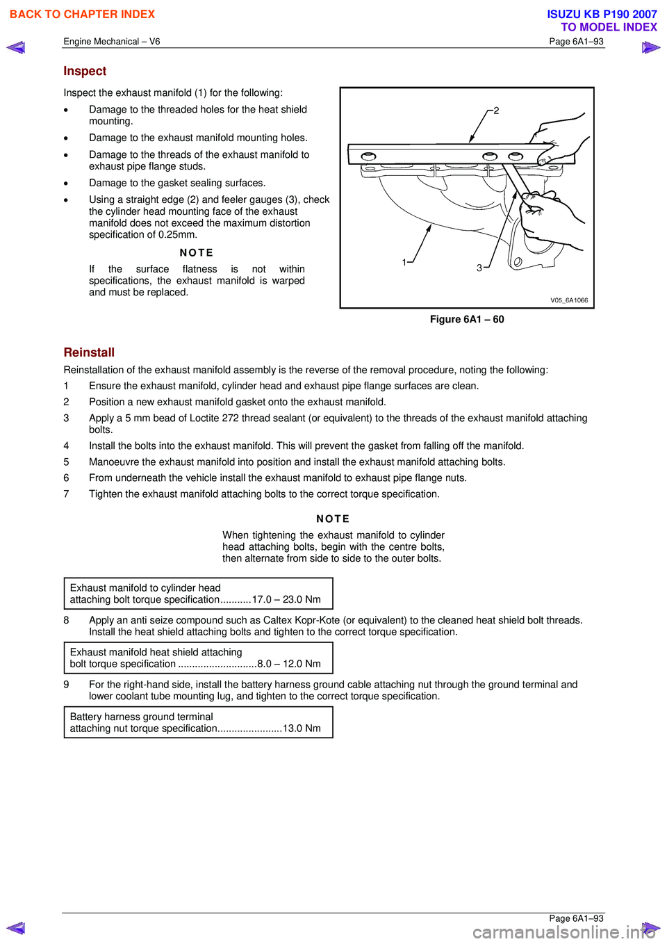
Inspect the exhaust manifold (1) for the following:
• Damage to the threaded holes for the heat shield
mounting.
• Damage to the exhaust manifold mounting holes.
• Damage to the threads of the exhaust manifold to
exhaust pipe flange studs.
• Damage to the gasket sealing surfaces.
• Using a straight edge (2) and feeler gauges (3), check
the cylinder head mounting face of the exhaust
manifold does not exceed the maximum distortion
specification of 0.25mm.
NOTE
If the surface flatness is not within
specifications, the exhaus t manifold is warped
and must be replaced.
Figure 6A1 – 60
Reinstall
Reinstallation of the exhaust manifold assembly is the reverse of the removal procedure, noting the following:
1 Ensure the exhaust manifold, cylinder head and exhaust pipe flange surfaces are clean.
2 Position a new exhaust manifold gasket onto the exhaust manifold.
3 Apply a 5 mm bead of Loctite 272 thread sealant (or equival ent) to the threads of the exhaust manifold attaching
bolts.
4 Install the bolts into the exhaust manifold. This will prevent the gasket from falling off the manifold.
5 Manoeuvre the exhaust manifold into position and install the exhaust manifold attaching bolts.
6 From underneath the vehicle install the exhaust manifold to exhaust pipe flange nuts.
7 Tighten the exhaust manifold attaching bolts to the correct torque specification.
NOTE
When tightening the exhaust manifold to cylinder
head attaching bolts, begin with the centre bolts,
then alternate from side to side to the outer bolts.
Exhaust manifold to cylinder head
attaching bolt torque spec ification ........... 17.0 – 23.0 Nm
8 Apply an anti seize compound such as Caltex Kopr-Kot e (or equivalent) to the cleaned heat shield bolt threads.
Install the heat shield attaching bolts and ti ghten to the correct torque specification.
Exhaust manifold heat shield attaching
bolt torque specificat ion ............................ 8.0 – 12.0 Nm
9 For the right-hand side, install the battery harness ground cable attaching nut through the ground terminal and
lower coolant tube mounting lug, and tighten to the correct torque specification.
Battery harness ground terminal
attaching nut torque s pecification.......................13.0 Nm
BACK TO CHAPTER INDEX
TO MODEL INDEX
ISUZU KB P190 2007
Page 2872 of 6020
Engine Mechanical – V6 Page 6A1–95
Page 6A1–95
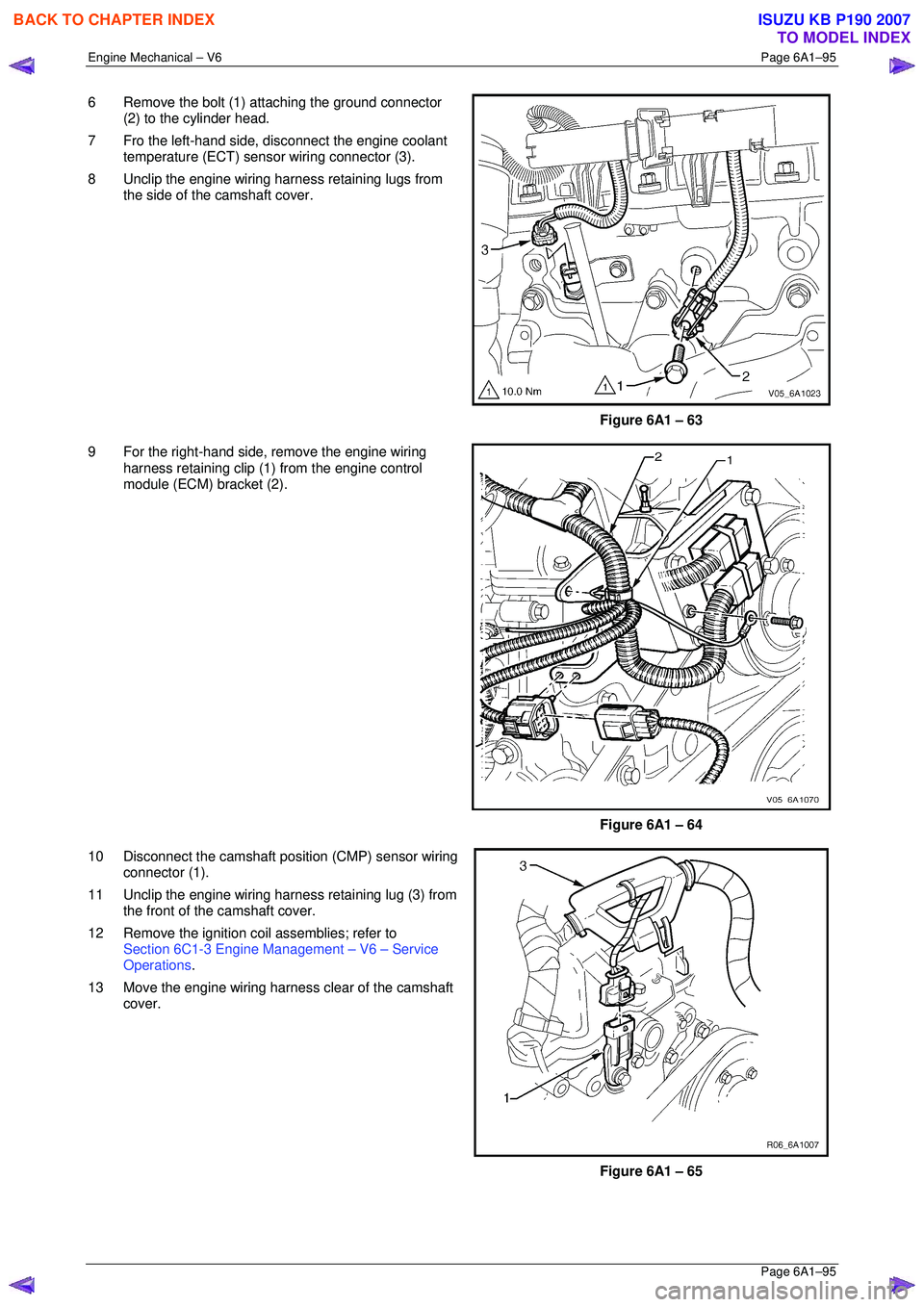
6 Remove the bolt (1) attaching the ground connector
(2) to the cylinder head.
7 Fro the left-hand side, disconnect the engine coolant temperature (ECT) sensor wiring connector (3).
8 Unclip the engine wiring harness retaining lugs from the side of the camshaft cover.
Figure 6A1 – 63
9 For the right-hand side, remove the engine wiring harness retaining clip (1) from the engine control
module (ECM) bracket (2).
Figure 6A1 – 64
10 Disconnect the camshaft position (CMP) sensor wiring connector (1).
11 Unclip the engine wiring harness retaining lug (3) from the front of the camshaft cover.
12 Remove the ignition coil assemblies; refer to Section 6C1-3 Engine Management – V6 – Service
Operations .
13 Move the engine wiring harness clear of the camshaft cover.
Figure 6A1 – 65
BACK TO CHAPTER INDEX
TO MODEL INDEX
ISUZU KB P190 2007
Page 2881 of 6020
Engine Mechanical – V6 Page 6A1–104
Page 6A1–104
3.15 Front Cover Assembly
Remove
1 Drain the engine coolant, refer to Section 6B1 Engine Cooling.
2 Remove the water outlet pipe and coolant pump assembly, refer to Section 6B1 Engine Cooling:
3 Remove the camsha ft covers, refer to 3.12 Camshaft Cover .
4 Remove the crankshaft bal ancer assembly, refer to 3.13 Crankshaft Balancer Assembly .
5 Disconnect the purge vent hose from the water outlet pipe.
NOTE
Do not disconnect the power steering pipes or
drain the power steering fluid.
6 Remove the power steering pump reservoir mounting bracket, refer to 3.8 Power Steering Pump Bracket.
7 Remove the camshaft position sensor, refer to Section 6C1-3 Engine Management – V6 – Service Operations.
NOTE
Do not disconnect the A/C compressor pipes.
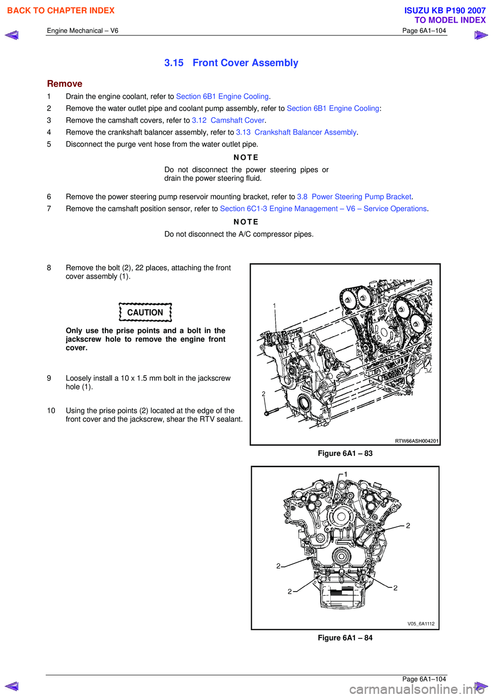
8 Remove the bolt (2), 22 places, attaching the front cover assembly (1).
CAUTION
Only use the prise points and a bolt in the
jackscrew hole to remove the engine front
cover.
9 Loosely install a 10 x 1.5 mm bolt in the jackscrew hole (1).
10 Using the prise points (2) located at the edge of the
front cover and the jackscrew, shear the RTV sealant.
Figure 6A1 – 83
Figure 6A1 – 84
BACK TO CHAPTER INDEX
TO MODEL INDEX
ISUZU KB P190 2007