2007 ISUZU KB P190 DTC CHECK
[x] Cancel search: DTC CHECKPage 1931 of 6020
6E-314 ENGINE CONTROL SYSTEM (4JK1/4JJ1)
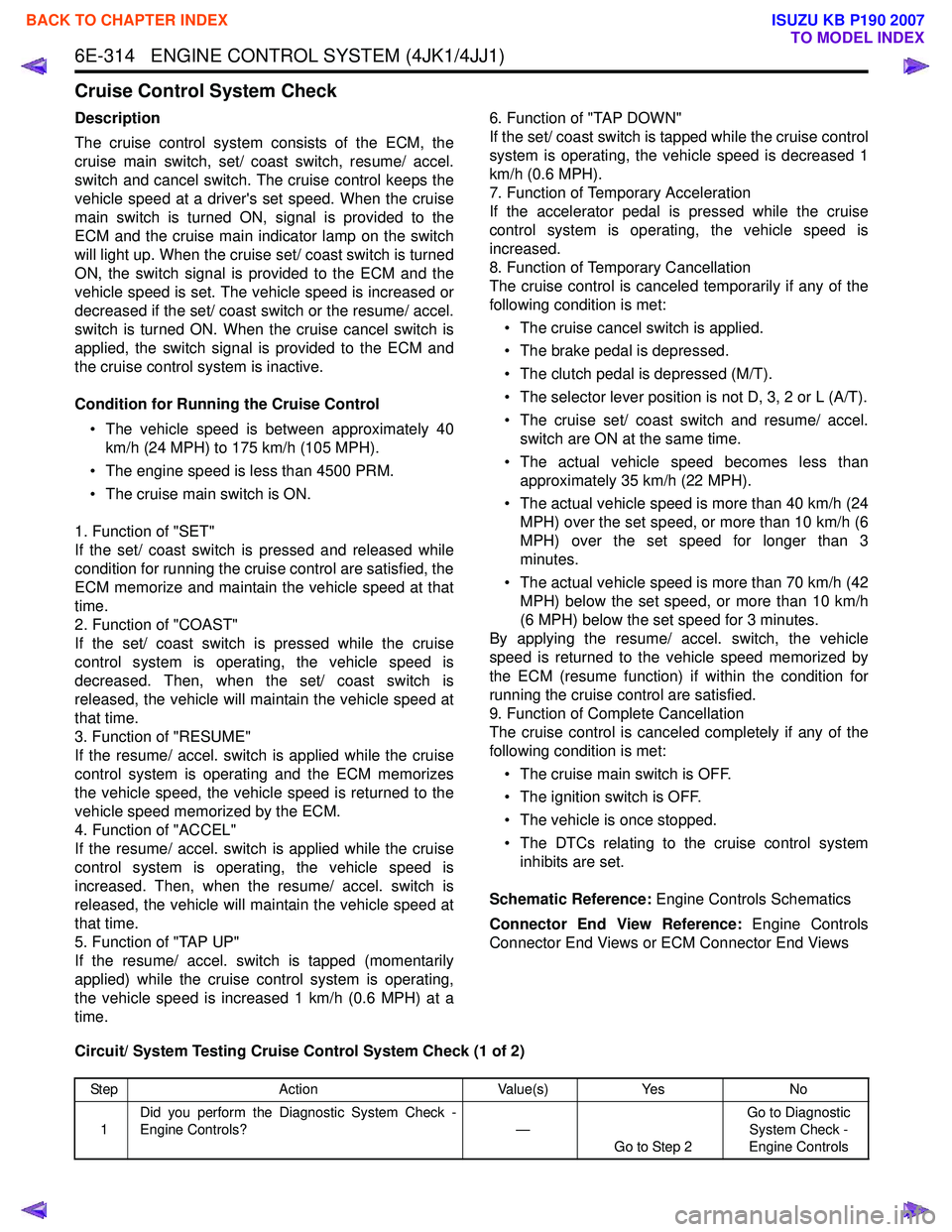
Cruise Control System Check
Description
The cruise control system consists of the ECM, the
cruise main switch, set/ coast switch, resume/ accel.
switch and cancel switch. The cruise control keeps the
vehicle speed at a driver's set speed. When the cruise
main switch is turned ON, signal is provided to the
ECM and the cruise main indicator lamp on the switch
will light up. When the cruise set/ coast switch is turned
ON, the switch signal is provided to the ECM and the
vehicle speed is set. The vehicle speed is increased or
decreased if the set/ coast switch or the resume/ accel.
switch is turned ON. When the cruise cancel switch is
applied, the switch signal is provided to the ECM and
the cruise control system is inactive.
Condition for Running the Cruise Control • The vehicle speed is between approximately 40 km/h (24 MPH) to 175 km/h (105 MPH).
• The engine speed is less than 4500 PRM.
• The cruise main switch is ON.
1. Function of "SET"
If the set/ coast switch is pressed and released while
condition for running the cruise control are satisfied, the
ECM memorize and maintain the vehicle speed at that
time.
2. Function of "COAST"
If the set/ coast switch is pressed while the cruise
control system is operating, the vehicle speed is
decreased. Then, when the set/ coast switch is
released, the vehicle will maintain the vehicle speed at
that time.
3. Function of "RESUME"
If the resume/ accel. switch is applied while the cruise
control system is operating and the ECM memorizes
the vehicle speed, the vehicle speed is returned to the
vehicle speed memorized by the ECM.
4. Function of "ACCEL"
If the resume/ accel. switch is applied while the cruise
control system is operating, the vehicle speed is
increased. Then, when the resume/ accel. switch is
released, the vehicle will maintain the vehicle speed at
that time.
5. Function of "TAP UP"
If the resume/ accel. switch is tapped (momentarily
applied) while the cruise control system is operating,
the vehicle speed is increased 1 km/h (0.6 MPH) at a
time. 6. Function of "TAP DOWN"
If the set/ coast switch is tapped while the cruise control
system is operating, the vehicle speed is decreased 1
km/h (0.6 MPH).
7. Function of Temporary Acceleration
If the accelerator pedal is pressed while the cruise
control system is operating, the vehicle speed is
increased.
8. Function of Temporary Cancellation
The cruise control is canceled temporarily if any of the
following condition is met:
• The cruise cancel switch is applied.
• The brake pedal is depressed.
• The clutch pedal is depressed (M/T).
• The selector lever position is not D, 3, 2 or L (A/T).
• The cruise set/ coast switch and resume/ accel. switch are ON at the same time.
• The actual vehicle speed becomes less than approximately 35 km/h (22 MPH).
• The actual vehicle speed is more than 40 km/h (24 MPH) over the set speed, or more than 10 km/h (6
MPH) over the set speed for longer than 3
minutes.
• The actual vehicle speed is more than 70 km/h (42 MPH) below the set speed, or more than 10 km/h
(6 MPH) below the set speed for 3 minutes.
By applying the resume/ accel. switch, the vehicle
speed is returned to the vehicle speed memorized by
the ECM (resume function) if within the condition for
running the cruise control are satisfied.
9. Function of Complete Cancellation
The cruise control is canceled completely if any of the
following condition is met:
• The cruise main switch is OFF.
• The ignition switch is OFF.
• The vehicle is once stopped.
• The DTCs relating to the cruise control system inhibits are set.
Schematic Reference: Engine Controls Schematics
Connector End View Reference: Engine Controls
Connector End Views or ECM Connector End Views
Circuit/ System Testing Cruise Control System Check (1 of 2)
Step Action Value(s)Yes No
1 Did you perform the Diagnostic System Check -
Engine Controls? —
Go to Step 2 Go to Diagnostic
System Check -
Engine Controls
BACK TO CHAPTER INDEX
TO MODEL INDEX
ISUZU KB P190 2007
Page 1937 of 6020
6E-320 ENGINE CONTROL SYSTEM (4JK1/4JJ1)
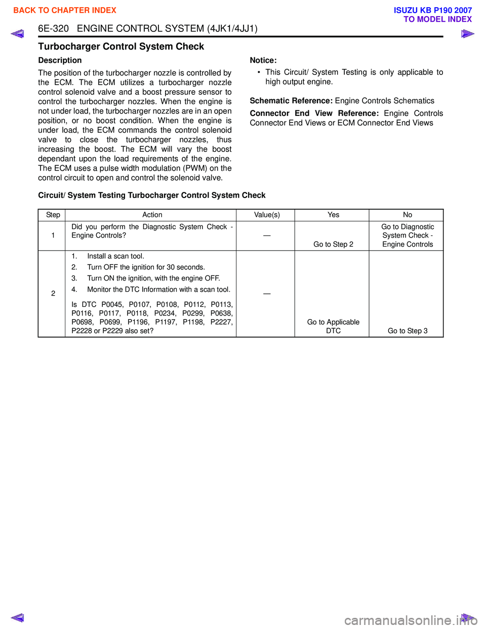
Turbocharger Control System Check
Description
The position of the turbocharger nozzle is controlled by
the ECM. The ECM utilizes a turbocharger nozzle
control solenoid valve and a boost pressure sensor to
control the turbocharger nozzles. When the engine is
not under load, the turbocharger nozzles are in an open
position, or no boost condition. When the engine is
under load, the ECM commands the control solenoid
valve to close the turbocharger nozzles, thus
increasing the boost. The ECM will vary the boost
dependant upon the load requirements of the engine.
The ECM uses a pulse width modulation (PWM) on the
control circuit to open and control the solenoid valve. Notice:
• This Circuit/ System Testing is only applicable to high output engine.
Schematic Reference: Engine Controls Schematics
Connector End View Reference: Engine Controls
Connector End Views or ECM Connector End Views
Circuit/ System Testing Turbocharger Control System Check
Step Action Value(s)Yes No
1 Did you perform the Diagnostic System Check -
Engine Controls? —
Go to Step 2 Go to Diagnostic
System Check -
Engine Controls
2 1. Install a scan tool.
2. Turn OFF the ignition for 30 seconds.
3. Turn ON the ignition, with the engine OFF.
4. Monitor the DTC Information with a scan tool.
Is DTC P0045, P0107, P0108, P0112, P0113,
P0116, P0117, P0118, P0234, P0299, P0638,
P0698, P0699, P1196, P1197, P1198, P2227,
P2228 or P2229 also set? —
Go to Applicable DTC Go to Step 3
BACK TO CHAPTER INDEX
TO MODEL INDEX
ISUZU KB P190 2007
Page 1940 of 6020
ENGINE CONTROL SYSTEM (4JK1/4JJ1) 6E-323
Symptoms - Engine Controls
Symptoms - Engine Controls
Important Preliminary Inspections Before Starting
Perform Diagnostic System Check - Engine Controls
before using the symptom tables, and verify that all of
the following are true:
• The ECM and malfunction indicator lamp (MIL)/ service vehicle soon (SVS) lamp are operating
correctly.
• The scan tool data is within the normal operating range. Refer to Scan Tool Data List in this section.
• Verify the customer concern and locate the correct symptom in the table of contents. Inspect the items
indicated under that symptom.
Visual and Physical Inspection
Several of the symptom procedures ask for careful
visual and physical inspection. This step is extremely
important. The visual and physical inspection can lead
to correcting a problem without further inspections, and
can save valuable time. Ensure that:
• The ECM grounds are clean, tight, and in their proper location.
• The vacuum hoses are not split or kinked, and properly connected. Inspect thoroughly for any
type of leak or restriction.
• The air intake ducts are not collapsed or damaged.
• The exhaust pipes are not collapsed or damaged.
• The engine harness wiring and terminals are properly connected and are not pinched or cut.
Intermittent
Important: Inspect for improper installation of electrical
components if an intermittent condition exists. Inspect
for aftermarket add-on electrical equipment devices,
lights, and cellular phones. Verify that no aftermarket
equipment is connected to the controller area network
(CAN) or other serial data circuit.
Important: The problem may or may not turn ON the
MIL/ SVS lamp or store a DTC. Faulty electrical
connections or wiring cause most intermittent
problems. Perform a careful visual and physical
inspection of the suspect connectors for the following
conditions:
• Improperly mated connector halves
• Terminals that are not seated
• Terminals that are damaged or improperly formed Reform or replace connector terminals in the problem
circuit in order to ensure proper contact tension.
Remove the terminal from the connector body in order
to inspect for poor terminal wire connection.
Road test the vehicle with the DMM connected to the
suspected circuit. An abnormal reading that occurs
when the malfunction occurs is a good indication that
there is a malfunction in the circuit being monitored.
Use the scan tool in order to help detect intermittent
conditions. Useful features of the Tech 2 scan tool
include the following:
• Trigger the Snapshot feature in order to capture and store engine parameters when the malfunction
occurs. Review this stored information in order to
see the specific running conditions that caused the
malfunction.
• Freeze Frame/ Failure Record can also aid in locating an intermittent condition. Review and
capture the information in the Freeze Frame/
Failure Record associated with the intermittent
DTC being diagnosed. Drive the vehicle within the
conditions that were present when the DTC
originally set.
• Use the Plot Function on the scan tool in order to plot selected data parameters. Review this stored
information to aid in locating an intermittent
problem. Refer to the scan tool Users Guide for
more information.
Use the data recording module (DRM) in order to help
detect intermittent conditions. The DRM has ability to
store engine log data when an event of DTC. Maximum
three log data can be stored in the DRM memory. If
more than maximum number of storage is set, oldest
log data is overwritten. However, if same DTC is set
within eight hours that DTC is not stored in the DRM
memory.
The manual trigger function is to store the log data by
an arbitrary operation of the driver when an event of
wrong vehicle performance that is instead of an event
of DTC. If the driver presses and releases the manual
trigger switch once, that time becomes a trigger and
one log data before and behind the trigger is stored in
the DRM memory. When there is a space in the DRM
memory, log data is stored in that space. However,
when more than maximum number of storage is set,
oldest log data is overwritten.
Refer to the DRM Users Guide for more information.
Important: If the intermittent condition exists as a start
and then stall, test for DTCs relating to the vehicle theft
deterrent system. Test for improper installation of
electrical options such as lights, cellular phones, etc..
Any of the following may cause an intermittent MIL/
SVS lamp with no stored DTC:
• The ECM grounds are loose or dirty. Refer to Engine Controls Schematics.
BACK TO CHAPTER INDEX
TO MODEL INDEX
ISUZU KB P190 2007
Page 1942 of 6020
ENGINE CONTROL SYSTEM (4JK1/4JJ1) 6E-325
Intermittent Conditions
ChecksAction
Definition:
The problem is not currently present but is indicated in DTC History.
OR
There is a customer complaint, but the symptom cannot currently be duplicated, if the problem is not DTC related.
Preliminary Checks • Refer to Symptoms - Engine Controls before starting.
Harness/ Connector Many intermittent open or shorted circuits are affected by harness/ connector
movement that is caused by vibration, engine torque, bumps/ rough pavement, etc.
Test for this type of condition by performing the applicable procedure from the following
list:
• Move related connectors and wiring while monitoring the appropriate scan tool data.
• Move related connectors and wiring with the component commanded ON, and OFF, with the scan tool. Observe the component operation.
• With the engine running, move related connectors and wiring while monitoring engine operation.
If harness or connector movement affects the data displayed, component/ system
operation, or engine operation, inspect and repair the harness/ connections as
necessary.
Electrical Connections or Wiring Poor electrical connections, terminal tension or wiring problems cause most intermittent. To perform the following inspections:
• Poor mating of the connector halves, or terminals improperly seated in the connector body.
• Improperly formed or damaged terminals. Test for poor terminal tension.
• Poor terminal to wire connections including terminals crimped over insulation. This requires removing the terminal from the connector body.
• Corrosion/ water intrusion. Pierced or damaged insulation can allow moisture to enter the wiring. The conductor can corrode inside the insulation, with little visible
evidence. Look for swollen and stiff sections of wire in the suspect circuits.
• Wires that are broken inside the insulation.
• Harness for pinched, cut or rubbed through wiring.
• Ensure that the wiring does not come in contact with hot exhaust components.
Control Module Power and Grounds
Component Power and Grounds Poor power or ground connections can cause widely varying symptoms.
• Test all control module power supply circuits. Many vehicles have multiple circuits supplying power to the control module. Other components in the system may have
separate power supply circuits that may also need to be tested. Inspect connections
at the module/ component connectors, fuses, and any intermediate connections
between the power source and the module/ component. A test lamp or a DMM may
indicate that voltage is present, but neither tests the ability of the circuit to carry
sufficient current. Ensure that the circuit can carry the current necessary to operate
the component.
• Test all control module ground and system ground circuits. The control module may have multiple ground circuits. Other components in the system may have separate
grounds that may also need to be tested. Inspect grounds for clean and tight
connections at the grounding point. Inspect the connections at the component and
in splice packs, where applicable. Ensure that the circuit can carry the current
necessary to operate the component.
BACK TO CHAPTER INDEX
TO MODEL INDEX
ISUZU KB P190 2007
Page 1943 of 6020
6E-326 ENGINE CONTROL SYSTEM (4JK1/4JJ1)
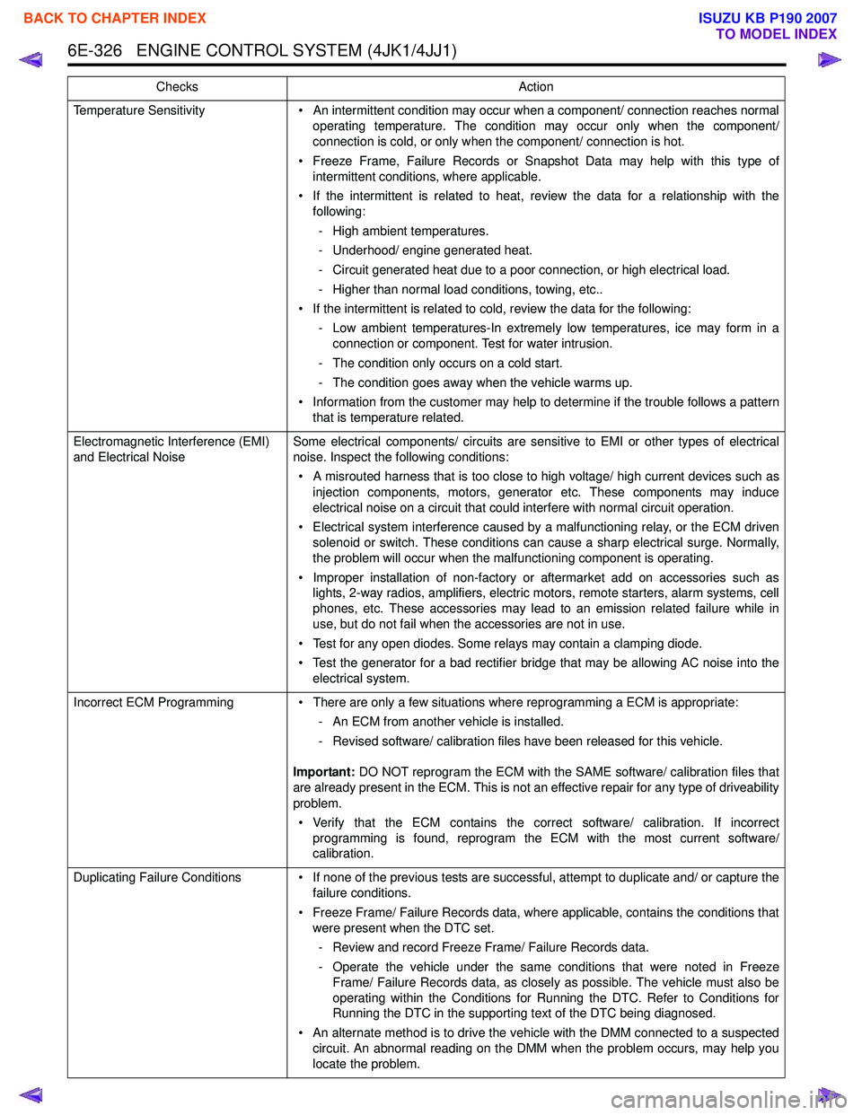
Temperature Sensitivity• An intermittent condition may occur when a component/ connection reaches normal
operating temperature. The condition may occur only when the component/
connection is cold, or only when the component/ connection is hot.
• Freeze Frame, Failure Records or Snapshot Data may help with this type of intermittent conditions, where applicable.
• If the intermittent is related to heat, review the data for a relationship with the following:
- High ambient temperatures.
- Underhood/ engine generated heat.
- Circuit generated heat due to a poor connection, or high electrical load.
- Higher than normal load conditions, towing, etc..
• If the intermittent is related to cold, review the data for the following: - Low ambient temperatures-In extremely low temperatures, ice may form in aconnection or component. Test for water intrusion.
- The condition only occurs on a cold start.
- The condition goes away when the vehicle warms up.
• Information from the customer may help to determine if the trouble follows a pattern that is temperature related.
Electromagnetic Interference (EMI)
and Electrical Noise Some electrical components/ circuits are sensitive to EMI or other types of electrical
noise. Inspect the following conditions:
• A misrouted harness that is too close to high voltage/ high current devices such as injection components, motors, generator etc. These components may induce
electrical noise on a circuit that could interfere with normal circuit operation.
• Electrical system interference caused by a malfunctioning relay, or the ECM driven solenoid or switch. These conditions can cause a sharp electrical surge. Normally,
the problem will occur when the malfunctioning component is operating.
• Improper installation of non-factory or aftermarket add on accessories such as lights, 2-way radios, amplifiers, electric motors, remote starters, alarm systems, cell
phones, etc. These accessories may lead to an emission related failure while in
use, but do not fail when the accessories are not in use.
• Test for any open diodes. Some relays may contain a clamping diode.
• Test the generator for a bad rectifier bridge that may be allowing AC noise into the electrical system.
Incorrect ECM Programming • There are only a few situations where reprogramming a ECM is appropriate:
- An ECM from another vehicle is installed.
- Revised software/ calibration files have been released for this vehicle.
Important: DO NOT reprogram the ECM with the SAME software/ calibration files that
are already present in the ECM. This is not an effective repair for any type of driveability
problem.
• Verify that the ECM contains the correct software/ calibration. If incorrect programming is found, reprogram the ECM with the most current software/
calibration.
Duplicating Failure Conditions • If none of the previous tests are successful, attempt to duplicate and/ or capture the failure conditions.
• Freeze Frame/ Failure Records data, where applicable, contains the conditions that were present when the DTC set.
- Review and record Freeze Frame/ Failure Records data.
- Operate the vehicle under the same conditions that were noted in Freeze Frame/ Failure Records data, as closely as possible. The vehicle must also be
operating within the Conditions for Running the DTC. Refer to Conditions for
Running the DTC in the supporting text of the DTC being diagnosed.
• An alternate method is to drive the vehicle with the DMM connected to a suspected circuit. An abnormal reading on the DMM when the problem occurs, may help you
locate the problem.
Checks
Action
BACK TO CHAPTER INDEX
TO MODEL INDEX
ISUZU KB P190 2007
Page 1944 of 6020
ENGINE CONTROL SYSTEM (4JK1/4JJ1) 6E-327
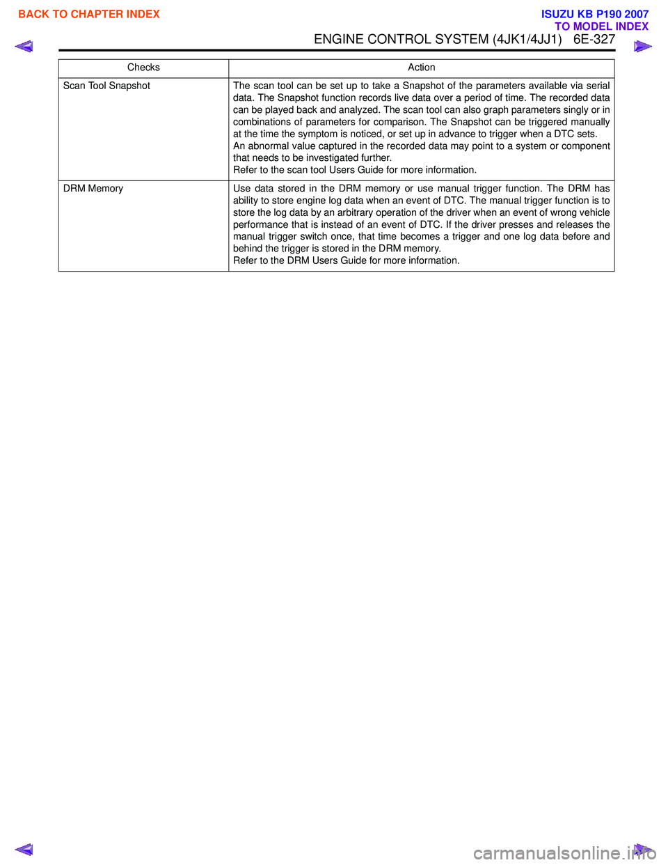
Scan Tool SnapshotThe scan tool can be set up to take a Snapshot of the parameters available via serial
data. The Snapshot function records live data over a period of time. The recorded data
can be played back and analyzed. The scan tool can also graph parameters singly or in
combinations of parameters for comparison. The Snapshot can be triggered manually
at the time the symptom is noticed, or set up in advance to trigger when a DTC sets.
An abnormal value captured in the recorded data may point to a system or component
that needs to be investigated further.
Refer to the scan tool Users Guide for more information.
DRM Memory Use data stored in the DRM memory or use manual trigger function. The DRM has
ability to store engine log data when an event of DTC. The manual trigger function is to
store the log data by an arbitrary operation of the driver when an event of wrong vehicle
performance that is instead of an event of DTC. If the driver presses and releases the
manual trigger switch once, that time becomes a trigger and one log data before and
behind the trigger is stored in the DRM memory.
Refer to the DRM Users Guide for more information.
Checks
Action
BACK TO CHAPTER INDEX
TO MODEL INDEX
ISUZU KB P190 2007
Page 1966 of 6020
ENGINE CONTROL SYSTEM (4JK1/4JJ1) 6E-349
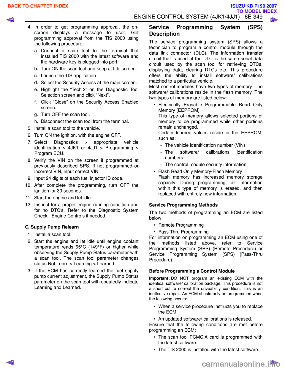
4. In order to get programming approval, the on-screen displays a message to user. Get
programming approval from the TIS 2000 using
the following procedure:
a. Connect a scan tool to the terminal that installed TIS 2000 with the latest software and
the hardware key is plugged into port.
b. Turn ON the scan tool and keep at title screen.
c. Launch the TIS application.
d. Select the Security Access at the main screen.
e. Highlight the “Tech 2” on the Diagnostic Tool Selection screen and click “Next”.
f. Click “Close” on the Security Access Enabled screen.
g. Turn OFF the scan tool.
h. Disconnect the scan tool from the terminal.
5. Install a scan tool to the vehicle.
6. Turn ON the ignition, with the engine OFF.
7. Select Diagnostics > appropriate vehicle identification > 4JK1 or 4JJ1 > Programming >
Program ECU.
8. Verify the VIN on the screen if programmed at previously described SPS. If not programmed or
incorrect VIN, input correct VIN.
9. Input 24 digits of each fuel injector ID code.
10. After complete the programming, turn OFF the ignition for 30 seconds.
11. Start the engine and let idle.
12. Inspect for a proper engine running condition and for no DTC's. Refer to the Diagnostic System
Check - Engine Controls if needed.
G. Supply Pump Relearn 1. Install a scan tool.
2. Start the engine and let idle until engine coolant temperature reads 65 °C (149 °F) or higher while
observing the Supply Pump Status parameter with
a scan tool. The scan tool parameter changes
status Not Learn > Learning > Learned.
3. If the ECM has correctly learned the fuel supply pump current adjustment, the Supply Pump Status
parameter on the scan tool will repeatedly indicate
Learning and Learned.Service Programming System (SPS)
Description
The service programming system (SPS) allows a
technician to program a control module through the
data link connector (DLC). The information transfer
circuit that is used at the DLC is the same serial data
circuit used by the scan tool for retrieving DTCs,
displaying data, clearing DTCs etc. This procedure
offers the ability to install software/ calibrations
matched to a particular vehicle.
Most control modules have two types of memory. The
software/ calibrations reside in the flash memory. The
two types of memory are listed below:
• Electrically Erasable Programmable Read Only Memory (EEPROM)
This type of memory allows selected portions of
memory to be programmed while other portions
remain unchanged.
Certain learned values reside in the EEPROM,
such as:
- The vehicle identification number (VIN)
- The software/ calibrations identification numbers
- The control module security information
• Flash Read Only Memory-Flash Memory Flash memory has increased memory storage
capacity. During programming, all information
within this type of memory is erased, and then
replaced with entirely new information.
Service Programming Methods
The two methods of programming an ECM are listed
below:
• Remote Programming
• Pass Thru Programming
For information on programming an ECM using one of
the methods listed above, refer to Service
Programming System (SPS) (Remote Procedure) or
Service Programming System (SPS) (Pass-Thru
Procedure).
Before Programming a Control Module
Important: DO NOT program an existing ECM with the
identical software/ calibration package. This procedure is not
a short cut to correct the driveability condition. This is an
ineffective repair. An ECM should only be programmed when
the following occurs:
• When a service procedure instructs you to replace the ECM.
• An updated software/ calibrations is released.
Ensure that the following conditions are met before
programming an ECM:
• The scan tool PCMCIA card is programmed with the latest software.
• The TIS 2000 is installed with the latest software.
BACK TO CHAPTER INDEX
TO MODEL INDEX
ISUZU KB P190 2007
Page 2172 of 6020
6E–2 ENGINE DRIVEABILITY AND EMISSIONS
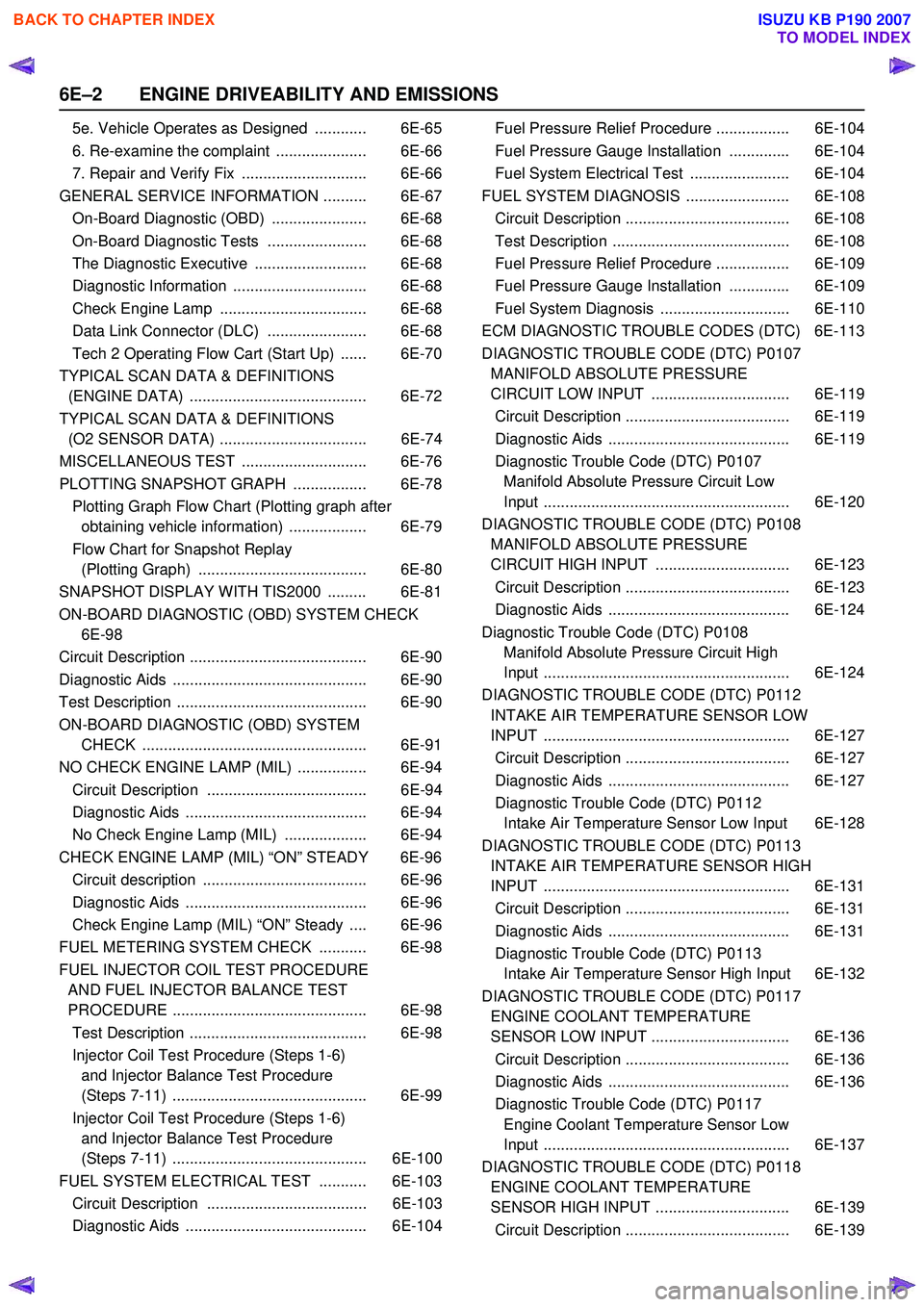
5e. Vehicle Operates as Designed ............ 6E-65
6. Re-examine the complaint ..................... 6E-66
7. Repair and Verify Fix ............................. 6E-66
GENERAL SERVICE INFORMATION .......... 6E-67 On-Board Diagnostic (OBD) ...................... 6E-68
On-Board Diagnostic Tests ....................... 6E-68
The Diagnostic Executive .......................... 6E-68
Diagnostic Information ............................... 6E-68
Check Engine Lamp .................................. 6E-68
Data Link Connector (DLC) ....................... 6E-68
Tech 2 Operating Flow Cart (Start Up) ...... 6E-70
TYPICAL SCAN DATA & DEFINITIONS (ENGINE DATA) ......................................... 6E-72
TYPICAL SCAN DATA & DEFINITIONS (O2 SENSOR DATA) .................................. 6E-74
MISCELLANEOUS TEST ............................. 6E-76
PLOTTING SNAPSHOT GRAPH ................. 6E-78 Plotting Graph Flow Chart (Plotting graph after obtaining vehicle information) .................. 6E-79
Flow Chart for Snapshot Replay (Plotting Graph) ....................................... 6E-80
SNAPSHOT DISPLAY WITH TIS2000 ......... 6E-81
ON-BOARD DIAGNOSTIC (OBD) SYSTEM CHECK 6E-98
Circuit Description ......................................... 6E-90
Diagnostic Aids ............................................. 6E-90
Test Description ............................................ 6E-90
ON-BOARD DIAGNOSTIC (OBD) SYSTEM CHECK .................................................... 6E-91
NO CHECK ENGINE LAMP (MIL) ................ 6E-94 Circuit Description ..................................... 6E-94
Diagnostic Aids .......................................... 6E-94
No Check Engine Lamp (MIL) ................... 6E-94
CHECK ENGINE LAMP (MIL) “ON” STEADY 6E-96 Circuit description ...................................... 6E-96
Diagnostic Aids .......................................... 6E-96
Check Engine Lamp (MIL) “ON” Steady .... 6E-96
FUEL METERING SYSTEM CHECK ........... 6E-98
FUEL INJECTOR COIL TEST PROCEDURE AND FUEL INJECTOR BALANCE TEST
PROCEDURE ............................................. 6E-98
Test Description ......................................... 6E-98
Injector Coil Test Procedure (Steps 1-6) and Injector Balance Test Procedure
(Steps 7-11) ............................................. 6E-99
Injector Coil Test Procedure (Steps 1-6) and Injector Balance Test Procedure
(Steps 7-11) ............................................. 6E-100
FUEL SYSTEM ELECTRICAL TEST ........... 6E-103 Circuit Description ..................................... 6E-103
Diagnostic Aids .......................................... 6E-104 Fuel Pressure Relief Procedure ................. 6E-104
Fuel Pressure Gauge Installation .............. 6E-104
Fuel System Electrical Test ....................... 6E-104
FUEL SYSTEM DIAGNOSIS ........................ 6E-108 Circuit Description ...................................... 6E-108
Test Description ......................................... 6E-108
Fuel Pressure Relief Procedure ................. 6E-109
Fuel Pressure Gauge Installation .............. 6E-109
Fuel System Diagnosis .............................. 6E-110
ECM DIAGNOSTIC TROUBLE CODES (DTC) 6E-113
DIAGNOSTIC TROUBLE CODE (DTC) P0107 MANIFOLD ABSOLUTE PRESSURE
CIRCUIT LOW INPUT ................................ 6E-119
Circuit Description ...................................... 6E-119
Diagnostic Aids .......................................... 6E-119
Diagnostic Trouble Code (DTC) P0107 Manifold Absolute Pressure Circuit Low
Input ......................................................... 6E-120
DIAGNOSTIC TROUBLE CODE (DTC) P0108 MANIFOLD ABSOLUTE PRESSURE
CIRCUIT HIGH INPUT ............................... 6E-123
Circuit Description ...................................... 6E-123
Diagnostic Aids .......................................... 6E-124
Diagnostic Trouble Code (DTC) P0108 Manifold Absolute Pressure Circuit High
Input ......................................................... 6E-124
DIAGNOSTIC TROUBLE CODE (DTC) P0112 INTAKE AIR TEMPERATURE SENSOR LOW
INPUT ......................................................... 6E-127
Circuit Description ...................................... 6E-127
Diagnostic Aids .......................................... 6E-127
Diagnostic Trouble Code (DTC) P0112 Intake Air Temperature Sensor Low Input 6E-128
DIAGNOSTIC TROUBLE CODE (DTC) P0113 INTAKE AIR TEMPERATURE SENSOR HIGH
INPUT ......................................................... 6E-131
Circuit Description ...................................... 6E-131
Diagnostic Aids .......................................... 6E-131
Diagnostic Trouble Code (DTC) P0113 Intake Air Temperature Sensor High Input 6E-132
DIAGNOSTIC TROUBLE CODE (DTC) P0117 ENGINE COOLANT TEMPERATURE
SENSOR LOW INPUT ................................ 6E-136
Circuit Description ...................................... 6E-136
Diagnostic Aids .......................................... 6E-136
Diagnostic Trouble Code (DTC) P0117 Engine Coolant Temperature Sensor Low
Input ......................................................... 6E-137
DIAGNOSTIC TROUBLE CODE (DTC) P0118 ENGINE COOLANT TEMPERATURE
SENSOR HIGH INPUT ............................... 6E-139
Circuit Description ...................................... 6E-139
BACK TO CHAPTER INDEX
TO MODEL INDEX
ISUZU KB P190 2007