2007 ISUZU KB P190 warning
[x] Cancel search: warningPage 5755 of 6020
RESTRAINT CONTROL SYSTEM 9A1-73
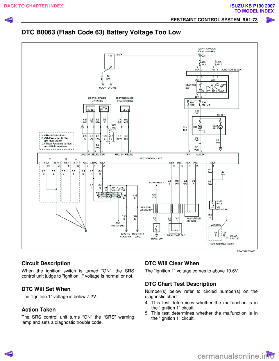
DTC B0063 (Flash Code 63) Battery Voltage Too Low
RTW 79ALF000301
Circuit Description
W hen the ignition switch is turned “ON", the SRS
control unit judge to "Ignition 1" voltage is normal or not.
DTC Will Set When
The "Ignition 1" voltage is below 7.2V.
Action Taken
The SRS control unit turns “ON” the “SRS” warning
lamp and sets a diagnostic trouble code.
DTC Will Clear When
The “Ignition 1" voltage comes to above 10.6V.
DTC Chart Test Description
Number(s) below refer to circled number(s) on the
diagnostic chart.
4. This test determines whether the malfunction is in the “Ignition 1” circuit.
5. This test determines whether the malfunction is in the “Ignition 1” circuit.
BACK TO CHAPTER INDEX TO MODEL INDEX
ISUZU KB P190 2007
Page 5757 of 6020
RESTRAINT CONTROL SYSTEM 9A1-75
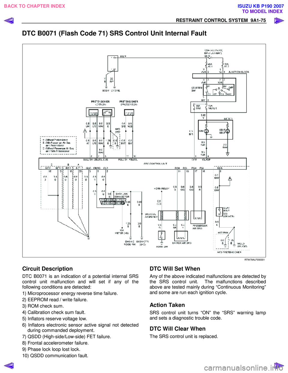
DTC B0071 (Flash Code 71) SRS Control Unit Internal Fault
RTW 79ALF000301
Circuit Description
DTC B0071 is an indication of a potential internal SRS
control unit malfunction and will set if any of the
following conditions are detected:
1) Microprocessor energy reverse time failure.
2) EEPROM read / write failure.
3) ROM check sum.
4) Calibration check sum fault.
5) Inflators reserve voltage low.
6) Inflators electronic sensor active signal not detected during commanded deployment.
7) QSDD (High-side/Low-side) FET failure.
8) Frontal accelerometer failure.
9) Phase lock loop lost lock.
10) QSDD communication fault.
DTC Will Set When
Any of the above indicated malfunctions are detected by
the SRS control unit. The malfunctions described
above are tested mainly during “Continuous Monitoring”
and some are run each ignition cycle.
Action Taken
SRS control unit turns “ON” the “SRS” warning lamp
and sets a diagnostic trouble code.
DTC Will Clear When
The SRS control unit is replaced.
BACK TO CHAPTER INDEX TO MODEL INDEXISUZU KB P190 2007
Page 5758 of 6020
9A1-76 RESTRAINT CONTROL SYSTEM
DTC B0071 (Flash Code 71) SRS Control Unit Internal Fault
WARNING: DURING SERVICE PROCEDURES. BE VERY CAREFUL WHEN HANDLING A SRS CONTROL UNIT.
NEVER STRIKE OR JAR THE SRS CONTROL UNIT. NEVER POWER UP THE SRS WHEN THE SRS CONTROL
UNIT IS NOT RIGIDLY ATTACHED TO THE VEHICLE. ALL SRS CONTROL UNIT AND MOUNTING BRACKET
FASTENERS MUST BE CAREFULLY TORQUED AND THE ARROW MUST BE POINTING TOWARD THE FRONT
OF THE VEHICLE TO ENSURE PROPER OPERATION OF THE SRS. THE SRS CONTROL UNIT COULD BE
ACTIVATED WHEN POWERED WHILE NOT RIGIDLY ATTACHED TO THE VEHICLE WHICH COULD CAUSE
DEPLOYMENT AND RESULT IN PERSONAL INJURY.
CAUTION: If DTC B0071 can not be cleared by Tech2, it is necessary to replace the SRS control unit.
Step Action Yes No
1 W as the “SRS Diagnostic System Check” performed?
Ignition switch
“LOCK”.
Replace SRS control unit.
Repeat the “SRS
Diagnostic System Check” Go to the “SRS
Diagnostic System Check”
BACK TO CHAPTER INDEX TO MODEL INDEXISUZU KB P190 2007
Page 5831 of 6020
CAB 10-73
Important Operations - Removal
1. Front Cover • W hile pushing the cover downward, pull it.
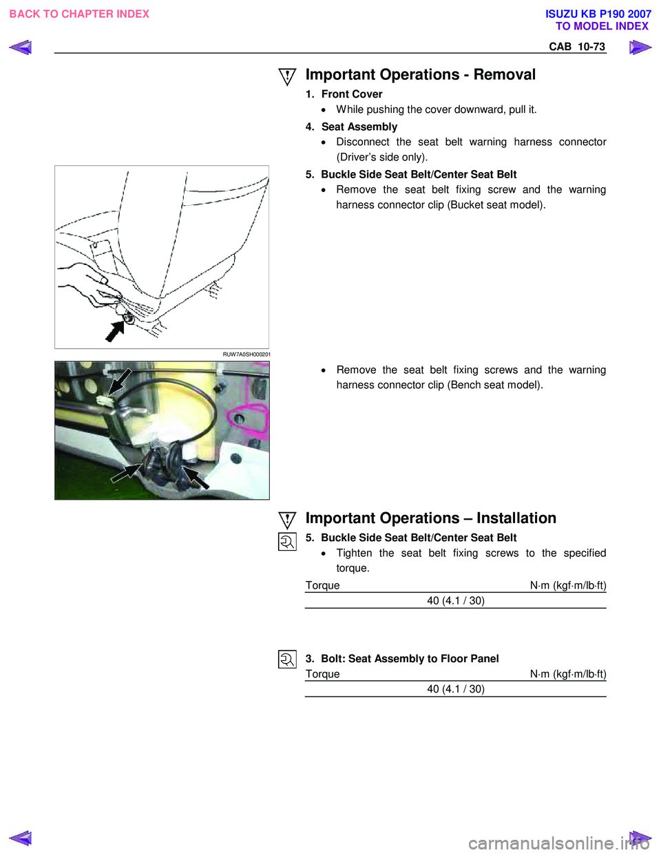
4. Seat Assembly • Disconnect the seat belt warning harness connecto
r
(Driver’s side only).
RUW 7A0SH000201
5. Buckle Side Seat Belt/Center Seat Belt
• Remove the seat belt fixing screw and the warning
harness connector clip (Bucket seat model).
• Remove the seat belt fixing screws and the warning
harness connector clip (Bench seat model).
Important Operations – Installation
5. Buckle Side Seat Belt/Center Seat Belt • Tighten the seat belt fixing screws to the specified
torque.
Torque N ⋅m (kgf ⋅m/lb ⋅ft)
40 (4.1 / 30)
3. Bolt: Seat Assembly to Floor Panel
Torque N ⋅m (kgf ⋅m/lb ⋅ft)
40 (4.1 / 30)
BACK TO CHAPTER INDEX TO MODEL INDEXISUZU KB P190 2007
Page 5837 of 6020
CAB 10-79
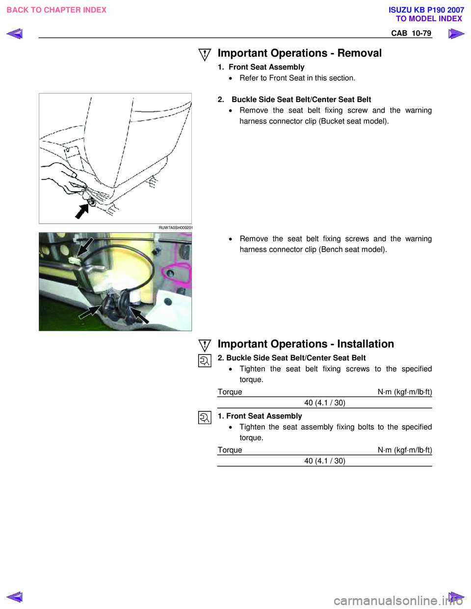
Important Operations - Removal
1. Front Seat Assembly • Refer to Front Seat in this section.
RUW 7A0SH000201
2. Buckle Side Seat Belt/Center Seat Belt
• Remove the seat belt fixing screw and the warning
harness connector clip (Bucket seat model).
• Remove the seat belt fixing screws and the warning
harness connector clip (Bench seat model).
Important Operations - Installation
2. Buckle Side Seat Belt/Center Seat Belt • Tighten the seat belt fixing screws to the specified
torque.
Torque N ⋅m (kgf ⋅m/lb ⋅ft)
40 (4.1 / 30)
1. Front Seat Assembly • Tighten the seat assembly fixing bolts to the specified
torque.
Torque N ⋅m (kgf ⋅m/lb ⋅ft)
40 (4.1 / 30)
BACK TO CHAPTER INDEX TO MODEL INDEXISUZU KB P190 2007
Page 5890 of 6020
IMMOBILIZER CONTROL SYSTEM (4JK1/4JJ1/HFV6) 11A-39
Notice:Keep away another key, another transponder
key, key number plate or other metal items from the
transponder key that is going to program.
11. The on-screen displays a message "Program more Transponder Keys?" If all transponder key(s) has
been programmed, press No and go to next step. If
more transponder key(s) need to be programmed,
press Yes and repeat from previous step.
12. The on-screen displays a message "Program Transponder Keys Programming Completed
Successfully!" if all transponder key(s)
programming has been completed, then press
Confirm.
13. Turn OFF the ignition for 30 seconds.
14. Verify the engine starts using all programmed transponder key(s).
ICU Resetting Procedure
1. Install a scan tool.
2. Turn ON the ignition, with the engine OFF.
3. Select Diagnostics > Appropriate vehicle identification > Body > Immobilizer > Additional
Functions > Reset Immobilizer.
4. The on-screen displays a message "See Checking Procedure Before Programming!", then press
Confirm.
5. Input four digits of correct security code that belongs to this vehicle and follow the on-screen
instructions.
Notice: An incorrect security code input causes a
security wait time.
6. The on-screen displays a message "Warning Engine will not start after Reset!", then press
Confirm.
7. The on-screen displays a message "Reset Immobilizer Reset Completed Successfully!" if ICU
resetting has been completed, then press Confirm.
8. Turn OFF the ignition for 30 seconds.
9. Verify the engine fails to run using all transponder key(s).
ICU Programming Procedure
1. Install a scan tool.
2. Turn ON the ignition, with the engine OFF.
3. Select Diagnostics > Appropriate vehicle identification > Body > Immobilizer > Programming
> Program Immobilizer Function or Immobilizer
Link To ECM/ PIM.
4. In order to get a programming approval, the on- screen displays a message to user. Get
programming approval from the TIS 2000 using
the following procedure: a. Connect a scan tool to the terminal that
installed TIS 2000 with the latest software and
the hardware key is plugged into port.
b. Turn ON the scan tool and keep at title screen.
c. Launch the TIS application.
d. Select the Security Access at the main screen.
e. Highlight "Tech 2" on the Diagnostic Tool Selection screen and click "Next".
f. Click "Close" on the Security Access Enabled screen.
g. Turn OFF the scan tool.
h. Disconnect the scan tool from the terminal.
5. Reinstall a scan tool to the vehicle.
6. Turn ON the ignition, with the engine OFF.
7. Select Diagnostics > Appropriate vehicle identification > Body > Immobilizer > Programming
> Program Immobilizer Function or Immobilizer
Link To ECM/ PIM.
8. The on-screen displays a message "See Checking Procedure Before Programming!", then press
Confirm.
9. Select "Immobilizer Installed" or select "Imoobilizer Replaced" Yes.
10. Select "PIM or ECM Replaced" No, if displayed.
11. Input four digits of correct security code that belongs to this vehicle and follow the on-screen
instructions. The on-screen instruction may repeat
twice.
Notice: An incorrect security code input causes a
security wait time.
12. Input 17 digits of correct VIN that is based on stamped VIN or affixed VIN plate on this vehicle.
13. Operate the ignition switch by following the on- screen instructions.
Notice: Keep away another key, another transponder
key, key number plate or other metal items from the
transponder key that is going to program.
14. The on-screen displays a message "Program more Transponder Keys?" If all transponder key(s) has
been programmed, press No and go to next step. If
more transponder key(s) need to be programmed,
press Yes and repeat from previous step.
15. The on-screen displays a message "Programming Successfully!" if ICU and all transponder key(s)
programming has been completed, then press
Confirm.
16. Turn OFF the ignition for 30 seconds.
17. Verify the engine starts using all programmed transponder key(s).
ECM Resetting Procedure
1. Install a scan tool.
2. Turn ON the ignition, with the engine OFF.
BACK TO CHAPTER INDEX TO MODEL INDEX
ISUZU KB P190 2007
Page 5891 of 6020
11A-40 IMMOBILIZER CONTROL SYSTEM (4JK1/4JJ1/HFV6)
3. Select Diagnostics > Appropriate vehicleidentification > Body > Immobilizer > Additional
Functions > Reset Engine Control Module. (4JK1/
4JJ1)
Select Diagnostics > Appropriate vehicle
identification > Engine > V6 Engine >
Programming > Reset ECU. (HFV6)
4. The on-screen may display a message "See Checking Procedure Before Programming!", then
press Confirm.
5. Input four digits of correct security code that belongs to this vehicle and follow the on-screen
instructions.
Notice: An incorrect security code input causes a
security wait time.
6. The on-screen displays a message "Warning! Engine will not start after Reset!", then press
Reset.
7. The on-screen displays a message "Reset Successfully!" if ECM resetting has been
completed, then press Confirm.
8. Turn OFF the ignition for 30 seconds.
9. Verify the engine fails to run using all transponder key(s).
ECM Programming Procedure
1. Install a scan tool.
2. Turn ON the ignition, with the engine OFF.
3. Select Diagnostics > Appropriate vehicle identification > Body > Immobilizer > Programming
> Program Immobilizer Function or Immobilizer
Link To ECM/ PIM.
4. In order to get a programming approval, the on- screen displays a message to user. Get
programming approval from the TIS 2000 using
the following procedure:
a. Connect a scan tool to the terminal that installed TIS 2000 with the latest software and
the hardware key is plugged into port.
b. Turn ON the scan tool and keep at title screen.
c. Launch the TIS application.
d. Select the Security Access at the main screen.
e. Highlight "Tech 2" on the Diagnostic Tool Selection screen and click "Next".
f. Click "Close" on the Security Access Enabled screen.
g. Turn OFF the scan tool.
h. Disconnect the scan tool from the terminal.
5. Reinstall a scan tool to the vehicle.
6. Turn ON the ignition, with the engine OFF.
7. Select Diagnostics > Appropriate vehicle identification > Body > Immobilizer > Programming
> Program Immobilizer Function or Immobilizer
Link To ECM/ PIM. 8. The on-screen may display a message "See
Checking Procedure Before Programming!", then
press Confirm.
9. Select "Imoobilizer Replaced" No and select "PIM or ECM Replaced" Yes, if displayed.
10. Input four digits of correct security code that belongs to this vehicle and follow the on-screen
instructions. The on-screen instruction may repeat
twice.
Notice: An incorrect security code input causes a
security wait time.
11. Select "Engine Controller Installed" or select "ECM Replaced".
12. Operate the ignition switch by following the on- screen instructions.
13. The on-screen displays a message "Programming Successfully!" if ECM programming has been
completed, then press Confirm.
14. Turn OFF the ignition for 30 seconds.
15. Verify the engine starts using all transponder key(s).
PIM Resetting Procedure
1. Install a scan tool.
2. Turn ON the ignition, with the engine OFF.
3. Select Diagnostics > Appropriate vehicle identification > Body > Powertrain Interface
Module > Security > Reset PIM.
4. Input four digits of correct security code that belongs to this vehicle and follow the on-screen
instructions.
Notice: An incorrect security code input causes a
security wait time.
5. The on-screen displays a message "Warning! Engine will not start after Reset!", then press
Reset.
6. The on-screen displays a message "Reset Completed Successfully!" if PIM resetting has
been completed, then press Confirm.
7. Turn OFF the ignition for 30 seconds.
PIM Programming Procedure
1. Install a scan tool.
2. Turn ON the ignition, with the engine OFF.
3. Select Diagnostics > Appropriate vehicle identification > Body > Immobilizer > Programming
> Immobilizer Link To ECM/ PIM.
4. In order to get a programming approval, the onscreen displays a message to user. Get
programming approval from the TIS 2000 using
the following procedure:
BACK TO CHAPTER INDEX TO MODEL INDEX
ISUZU KB P190 2007
Page 5900 of 6020
11A-2 IMMOBILIZER SYSTEM (C24SE, 4JA1-T)
B0007 NO ENGINE REQUEST RECEIVED ......11A-41
B0008 W RONG TRANSPONDER KEY .............11A-43
B0009 NO TRANSPONDER KEY
PROGRAMMED ................................................... 11A-44
B0010 UNKNOW N TRANSPONDER KEY ........11A-45
B0011 TRANSPONDER KEY PROBLEM
(Only 4JA1-T Engine) .......................................11A-46
B0012 W RONG TRANSPONDER KEY
(Only 4JA1-T Engine) .......................................11A-48
B0013 IMMOBILIZER NOT PROGRAMMED
(Only 4JA1-T Engine) .......................................11A-49
B0014 NO TRANSPONDER KEY
PROGRAMMED (Only 4JA1-T Engine) ...........11A-50
B0015 FREQUENCY SIGNAL LOW
(Only 4JA1-T Engine) ........................................11A-51
B0016 FREQUENCY SIGNAL HIGH
(Only 4JA1-T Engine) .......................................11A-52
B0023 IMMOBILIZER COIL CIRCUIT
(ANTENNA COIL FAULT)
(Only 4JA1-T Engine) ....................................... 11A-53
B0024 W RONG TRANSPONDER KEY
(Only 4JA1-T Engne) ........................................ 11A-54
B0055 EEPROM ERROR ................................. 11A-55
Special Tool ............................................................ 11A-56
Service Precaution
WARNING: THIS VEHICLE HAS A SUPPLEMENTAL
RESTRAINT SYSTEM (SRS). REFER TO THE SRS
COMPONENT AND WIRING LOCATION VIEW IN
ORDER TO DETERMINE WHETHER YOU ARE
PERFORMING SERVICE ON OR NEAR THE SRS
COMPONENTS OR THE SRS WIRING. WHEN YOU
ARE PERFORMING SERVICE ON OR NEAR THE
SRS COMPONENTS OR THE SRS WIRING, REFER
TO THE SRS SERVICE INFORMATION. FAILURE TO
FOLLOW WARNINGS COULD RESULT IN
POSSIBLE AIR BAG DEPLOYMENT, PERSONAL
INJURY, OR OTHERWISE UNNEEDED SRS SYSTEM
REPAIRS.
CAUTION: Always use the correct fastener in the
proper location. When you replace a fastener, use
ONLY the exact part number for that application.
ISUZU will call out those fasteners that require a
replacement after removal. ISUZU will also call out
the fasteners that require thread lockers or thread
sealant. UNLESS OTHERWISE SPECIFIED, do not
use supplemental coatings (Paints, greases, o
r
other corrosion inhibitors) on threaded fasteners or
fastener joint interfaces. Generally, such coatings
adversely affect the fastener torque and the joint
clamping force, and may damage the fastener.
When you install fasteners, use the correct
tightening sequence and specifications. Following
these instructions can help you avoid damage to
parts and systems.
BACK TO CHAPTER INDEX
TO MODEL INDEX
ISUZU KB P190 2007