2007 ISUZU KB P190 troubleshooting engine
[x] Cancel search: troubleshooting enginePage 2004 of 6020
6-4 ENGINE DIAGNOSIS (C24SE)
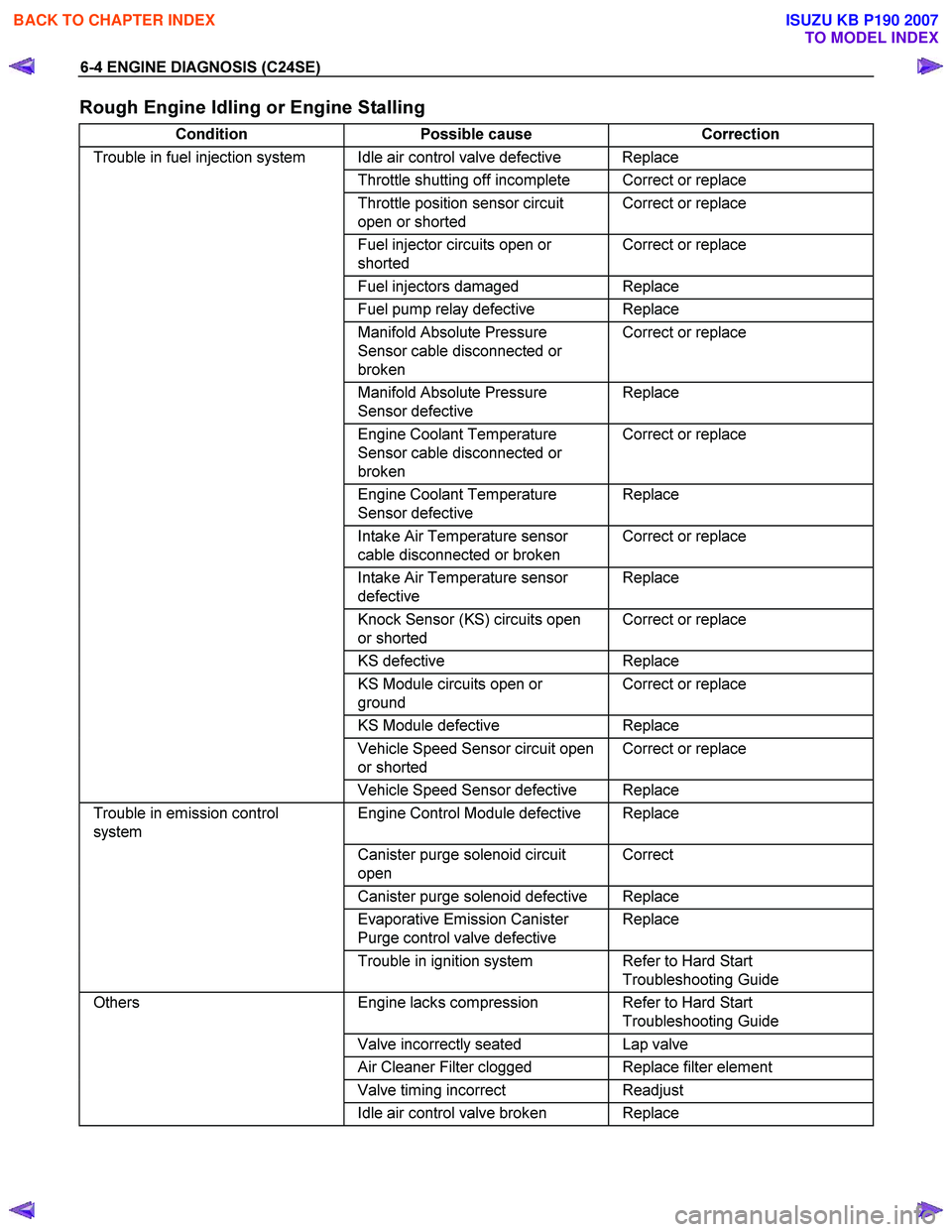
Rough Engine Idling or Engine Stalling
Condition Possible cause Correction
Trouble in fuel injection system Idle air control valve defective Replace
Throttle shutting off incomplete Correct or replace
Throttle position sensor circuit
open or shorted Correct or replace
Fuel injector circuits open or
shorted Correct or replace
Fuel injectors damaged Replace
Fuel pump relay defective Replace
Manifold Absolute Pressure
Sensor cable disconnected or
broken Correct or replace
Manifold Absolute Pressure
Sensor defective Replace
Engine Coolant Temperature
Sensor cable disconnected or
broken Correct or replace
Engine Coolant Temperature
Sensor defective Replace
Intake Air Temperature sensor
cable disconnected or broken Correct or replace
Intake Air Temperature sensor
defective Replace
Knock Sensor (KS) circuits open
or shorted Correct or replace
KS
defective Replace
KS Module circuits open or
ground Correct or replace
KS Module defective Replace
Vehicle Speed Sensor circuit open
or shorted Correct or replace
Vehicle Speed Sensor defective Replace
Trouble in emission control
system Engine Control Module defective Replace
Canister purge solenoid circuit
open Correct
Canister purge solenoid defective Replace
Evaporative Emission Canister
Purge control valve defective Replace
Trouble in ignition system Refer to Hard Start
Troubleshooting Guide
Others Engine lacks compression Refer to Hard Start
Troubleshooting Guide
Valve incorrectly seated Lap valve
Air Cleaner Filter clogged Replace filter element
Valve timing incorrect Readjust
Idle air control valve broken Replace
BACK TO CHAPTER INDEX
TO MODEL INDEX
ISUZU KB P190 2007
Page 2007 of 6020
ENGINE DIAGNOSIS (C24SE) 6-7
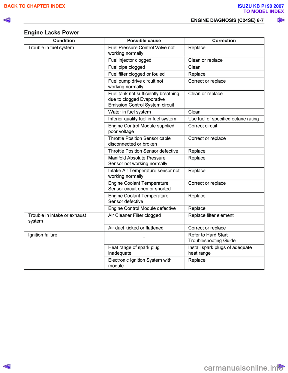
Engine Lacks Power
Condition Possible cause Correction
Trouble in fuel system Fuel Pressure Control Valve not
working normally Replace
Fuel injector clogged Clean or replace
Fuel pipe clogged Clean
Fuel filter clogged or fouled Replace
Fuel pump drive circuit not
working normally Correct or replace
Fuel tank not sufficiently breathing
due to clogged Evaporative
Emission Control System circuit Clean or replace
Water in fuel system Clean
Inferior quality fuel in fuel system Use fuel of specified octane rating
Engine Control Module supplied
poor voltage Correct circuit
Throttle Position Sensor cable
disconnected or broken Correct or replace
Throttle Position Sensor defective Replace
Manifold Absolute Pressure
Sensor not working normally Replace
Intake Air Temperature sensor not
working normally Replace
Engine Coolant Temperature
Sensor circuit open or shorted Correct or replace
Engine Coolant Temperature
Sensor defective Replace
Engine Control Module defective Replace
Trouble in intake or exhaust
system Air Cleaner Filter clogged Replace filter element
Air duct kicked or flattened Correct or replace
Ignition failure
- Refer to Hard Start
Troubleshooting Guide
Heat range of spark plug
inadequate Install spark plugs of adequate
heat range
Electronic Ignition System with
module Replace
BACK TO CHAPTER INDEX
TO MODEL INDEX
ISUZU KB P190 2007
Page 2009 of 6020
ENGINE DIAGNOSIS (C24SE) 6-9
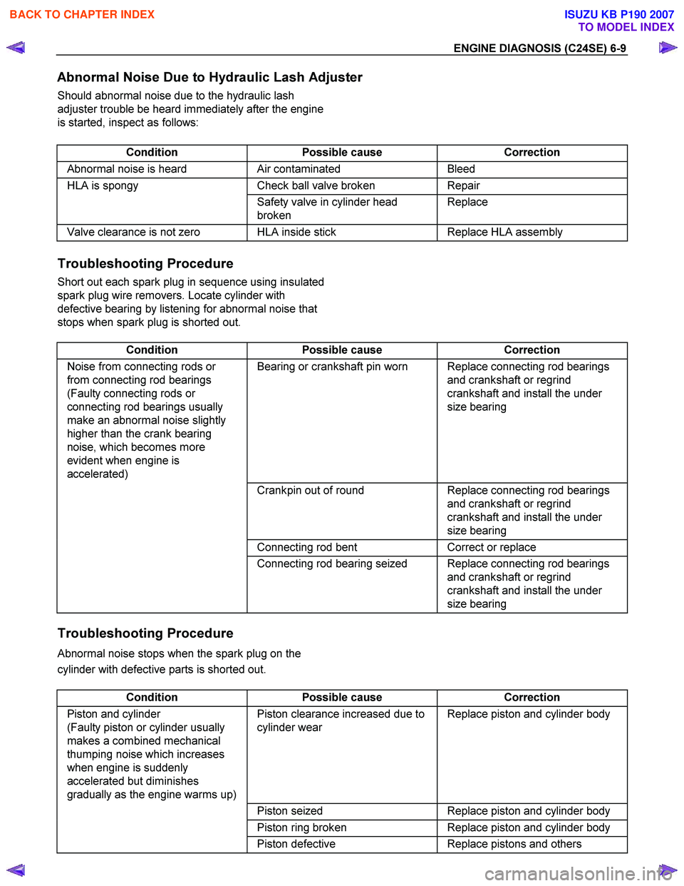
Abnormal Noise Due to Hydraulic Lash Adjuster
Should abnormal noise due to the hydraulic lash
adjuster trouble be heard immediately after the engine
is started, inspect as follows:
Condition Possible cause Correction
Abnormal noise is heard Air contaminated Bleed
HLA is spongy Check ball valve broken Repair
Safety valve in cylinder head
broken Replace
Valve clearance is not zero HLA inside stick
Replace HLA assembly
Troubleshooting Procedure
Short out each spark plug in sequence using insulated
spark plug wire removers. Locate cylinder with
defective bearing by listening for abnormal noise that
stops when spark plug is shorted out.
Condition Possible cause Correction
Noise from connecting rods or
from connecting rod bearings
(Faulty connecting rods or
connecting rod bearings usually
make an abnormal noise slightly
higher than the crank bearing
noise, which becomes more
evident when engine is
accelerated) Bearing or crankshaft pin worn Replace connecting rod bearings
and crankshaft or regrind
crankshaft and install the under
size bearing
Crankpin out of round Replace connecting rod bearings
and crankshaft or regrind
crankshaft and install the under
size bearing
Connecting rod bent Correct or replace
Connecting rod bearing seized Replace connecting rod bearings
and crankshaft or regrind
crankshaft and install the under
size bearing
Troubleshooting Procedure
Abnormal noise stops when the spark plug on the
cylinder with defective parts is shorted out.
Condition Possible cause Correction
Piston and cylinder
(Faulty piston or cylinder usually
makes a combined mechanical
thumping noise which increases
when engine is suddenly
accelerated but diminishes
gradually as the engine warms up) Piston clearance increased due to
cylinder wear Replace piston and cylinder body
Piston seized Replace piston and cylinder body
Piston ring broken Replace piston and cylinder body
Piston defective Replace pistons and others
BACK TO CHAPTER INDEX
TO MODEL INDEX
ISUZU KB P190 2007
Page 2010 of 6020
6-10 ENGINE DIAGNOSIS (C24SE)
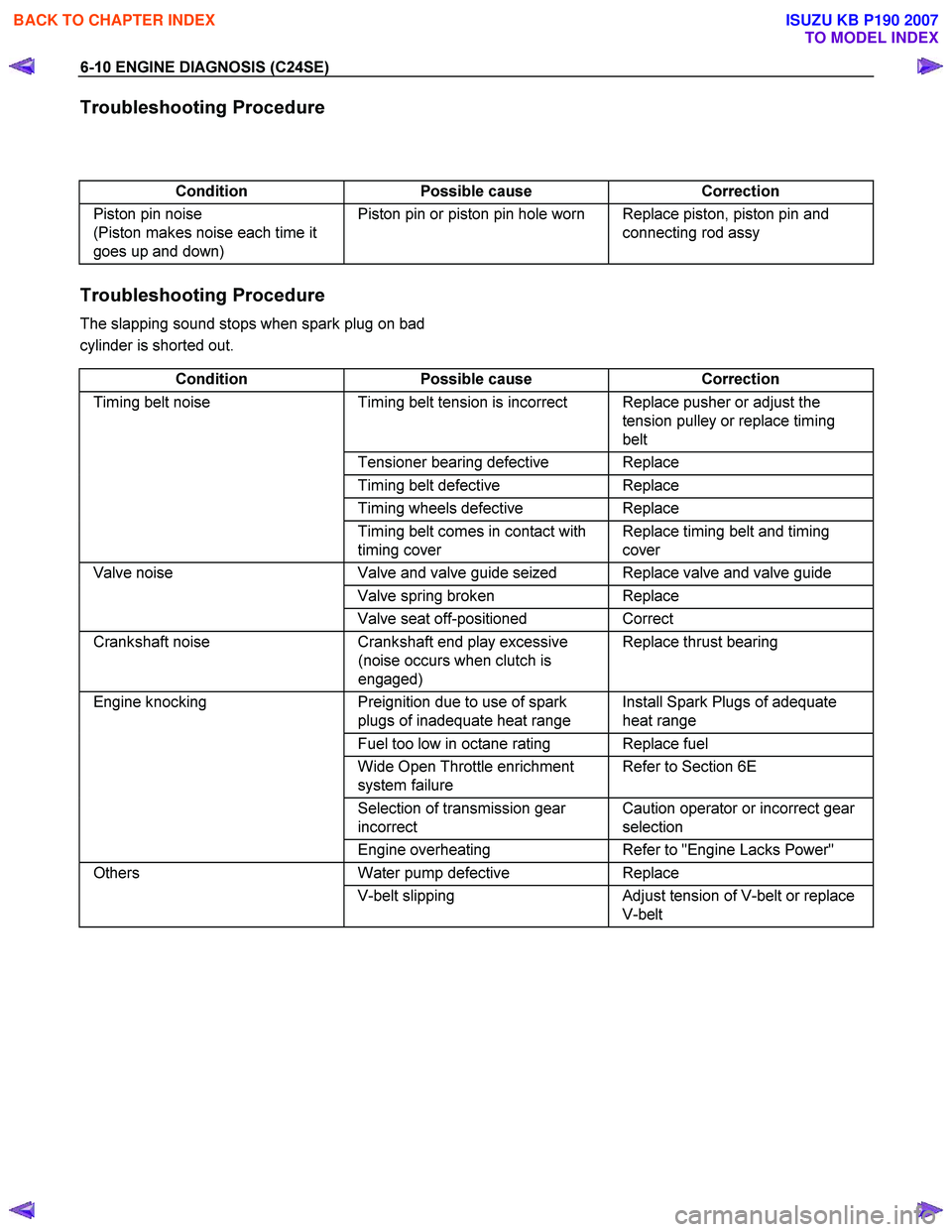
Troubleshooting Procedure
Condition Possible cause Correction
Piston pin noise
(Piston makes noise each time it
goes up and down) Piston pin or piston pin hole worn Replace piston, piston pin and
connecting rod assy
Troubleshooting Procedure
The slapping sound stops when spark plug on bad
cylinder is shorted out.
Condition Possible cause Correction
Timing belt noise Timing belt tension is incorrect Replace pusher or adjust the
tension pulley or replace timing
belt
Tensioner bearing defective Replace
Timing belt defective Replace
Timing wheels defective Replace
Timing belt comes in contact with
timing cover Replace timing belt and timing
cover
Valve noise Valve and valve guide seized Replace valve and valve guide
Valve spring broken Replace
Valve seat off-positioned Correct
Crankshaft noise Crankshaft end play excessive
(noise occurs when clutch is
engaged) Replace thrust bearing
Engine knocking
Preignition due to use of spark
plugs of inadequate heat range Install Spark Plugs of adequate
heat range
Fuel too low in octane rating Replace fuel
Wide Open Throttle enrichment
system failure Refer to Section 6E
Selection of transmission gear
incorrect Caution operator or incorrect gear
selection
Engine overheating Refer to "Engine Lacks Power"
Others Water pump defective Replace
V-belt slipping Adjust tension of V-belt or replace
V-belt
BACK TO CHAPTER INDEX
TO MODEL INDEX
ISUZU KB P190 2007
Page 2013 of 6020
ENGINE DIAGNOSIS (C24SE) 6-13
Fuel Consumption Excessive
Condition Possible cause Correction
Trouble in fuel system Mixture too rich or too lean due to
trouble in fuel injection system Refer to "Abnormal Combustion"
Fuel cut function does not act Refer to "Abnormal Combustion"
Trouble in ignition system Misfiring or abnormal combustion
due to trouble in ignition system Refer to Hard Start or Abnormal
Combustion Troubleshooting
Guide
Others Engine idle speed too high Reset Idle Air Control Valve
Returning of accelerator control
sluggish Correct
Fuel system leakage Correct or replace
Clutch slipping Correct
Brake drag Correct
Selection of transmission gear
incorrect Caution operator of incorrect gear
selection
Oil Problems
Condition Possible cause Correction
Oil pressure too low Wrong oil in use Replace with correct engine oil
Relief valve sticking Replace
Oil pump not operating properly Correct or replace
Oil pump strainer clogged Clean or replace strainer
Oil pump worn Replace
Oil pressure gauge defective Correct or replace
Crankshaft bearing or connecting
rod bearing worn Replace
Oil contamination
Wrong oil in use Replace with new engine oil
Oil filter clogged Replace oil filter
Cylinder head gasket damage Replace gasket
Burned gases leaking Replace piston and piston rings or
rebore cylinders
Oil not reaching valve system Oil passage in cylinder head or cylinder body clogged Clean or correct
Engine Oil Pressure Check
1. Check for dirt, gasoline or water in the engine
oil.
a. Check the viscosity of the oil.
b. Change the oil if the viscosity is outside the specified standard.
c. Refer to the "Maintenance and Lubrication" section of this manual.
2. Check the engine oil level. The level should fall somewhere between the
"ADD" and the "FULL" marks on the oil level
dipstick.
If the oil level does not reach the "ADD" mark on
the oil level dipstick, engine oil must be added.
3. Remove the oil pressure unit.
4. Install an oil pressure gauge.
5. Start the engine and allow the engine to reach normal operating temperature (About 80 °C).
6. Measure the oil pressure.
Oil pressure should be:
150 kPa(21.8 psi) at idle speed.
7. Stop the engine.
8. Remove the oil pressure gauge
9. Install the oil pressure unit.
10. Start the engine and check for leaks.
BACK TO CHAPTER INDEX
TO MODEL INDEX
ISUZU KB P190 2007
Page 2171 of 6020
SECTION 6E
TABLE OF CONTENTS
C24SE ENGINE DRIVEABILITY AND EMISSIONS
ABBREVIATIONS CHARTS ......................... 6E-6
ECM Circuit Diagram (1/2) ............................ 6E-11
ECM Circuit Diagram (2/2) ............................ 6E-12
GROUND POINT CHART - LHD G.EXP (1/4) 6E-13
GROUND POINT CHART - RHD G.EXP (1/4) 6E-17
LOCATION ................................................... 6E-21
CABLE HARNESS & CONNECTOR LOCATION .............................................. 6E-23
CABLE HARNESS & CONNECTOR LOCATION - LHD ................................... 6E-24
CABLE HARNESS & CONNECTOR LOCATION - RHD ................................... 6E-25
CONNECTOR LIST ...................................... 6E-28
RELAY AND FUSE ....................................... 6E-30
RELAY AND FUSE BOX LOCATION (LHD & RHD) ........................................... 6E-30
FUSE AND RELAY LOCATION (LHD & RHD) 6E-32
ECM WIRING DIAGRAM (1/9) ..................... 6E-33
ECM WIRING DIAGRAM (2/9) ..................... 6E-34
ECM WIRING DIAGRAM (3/9) ..................... 6E-35
ECM WIRING DIAGRAM (4/9) ..................... 6E-36
ECM WIRING DIAGRAM (5/9) ..................... 6E-37
ECM WIRING DIAGRAM (6/9) ..................... 6E-38
ECM WIRING DIAGRAM (7/9) ..................... 6E-39
ECM WIRING DIAGRAM (8/9) ..................... 6E-40
ECM WIRING DIAGRAM (9/9) ..................... 6E-41
ECM CONNECTOR PIN ASSIGNMENT & OUTPUT SIGNAL .................................... 6E-42
GENERAL DESCRIPTION FOR ECM AND SENSORS ............................................... 6E-48
Engine Control Module (ECM) ................... 6E-48
Manifold Absolute Pressure (MAP) Sensor 6E-48
Throttle Position Sensor (TPS) .................. 6E-49
Idle Air Control (IAC) Valve ....................... 6E-49
Crankshaft Position (CKP) Sensor ............ 6E-50
Knock Sensor (KS) .................................... 6E-50
Engine Coolant Temperature (ECT) Sensor 6E-50
Intake Air Temperature (IAT) Sensor ........ 6E-51
Vehicle Speed Sensor (VSS) .................... 6E-51
Heated Oxygen (O
2) Sensor ..................... 6E-51
GENERAL DESCRIPTION FOR FUEL METERING .............................................. 6E-52 Battery Voltage Correction Mode ............... 6E-52
Clear Flood Mode ...................................... 6E-52
Deceleration Fuel Cutoff (DFCO) Mode .... 6E-52
Engine Speed/ Vehicle Speed/ Fuel Disable Mode ........................................................ 6E-52
Acceleration Mode ..................................... 6E-52
Fuel Cutoff Mode ....................................... 6E-52
Starting Mode ............................................ 6E-52
Run Mode .................................................. 6E-52
Fuel Metering System Components .......... 6E-53
Fuel Injector ............................................... 6E-53
Fuel Pressure Regulator ............................ 6E-53
Fuel Rail ..................................................... 6E-53
Fuel Pump Electrical Circuit ....................... 6E-53
Thottle Body Unit ....................................... 6E-53
GENERAL DESCRIPTION FOR ELECTRIC IGNITION SYSTEM ................................. 6E-54
Spark Plug ................................................. 6E-54
GENERAL DESCRIPTION FOR EVAPORATIVE EMISSION SYSTEM ............................... 6E-57
EVAP Emission Control System Purpose .. 6E-57
EVAP Emission Control System Operation 6E-57
System Fault Detection .............................. 6E-57
POSITIVE CRANKCASE VENTILATION (PCV) SYSTEM .................................................. 6E-59
Crankcase Ventilation System Purpose .... 6E-59
A/C CLUTCH DIAGNOSIS ........................ 6E-60
A/C Clutch Circuit Operation ...................... 6E-60
A/C Clutch Circuit Purpose ........................ 6E-60
A/C Request Signal ................................... 6E-60
ISUZU STRATEGY BASED DIAGNOSTICS 6E-61
Overview .................................................... 6E-61
STRATEGY BASED DIAGNOSTICS CHART 6E-61 Diagnostic Thought Process ...................... 6E-62
1. Verify the Complaint .............................. 6E-62
2. Perform Preliminary Checks .................. 6E-62
3. Check Bulletins and Troubleshooting Hints 6E-63
4. Perform Service Manual Diagnostic Checks 6E-63
5a and 5b. Perform Service Manual Diagnostic Procedures .............................................. 6E-63
5c. Technician Self Diagnoses .................. 6E-63
5d. Intermittent Diagnosis .......................... 6E-64
6 E –1
E N GINE DRIV EABILITY AND E M IS SIONS
BACK TO CHAPTER INDEX
TO MODEL INDEX
ISUZU KB P190 2007
Page 2233 of 6020
ENGINE DRIVEABILITY AND EMISSIONS 6E–63
3. Check Bulletins and Troubleshooting Hints
NOTE: As estimated 30 percent of successful vehicle
repairs are diagnosed with this step!
What you should do
You should have enough information gained from
preliminary checks to accurately search for a bulletin
and other related service information. Some service
manual sections provide troubleshooting hints that
match symptoms with specific complaints.
What resources you should use
You should use the following resources for assistance in
checking for bulletins and troubleshooting hints:
• Printed bulletins
• Access ISUZU Bulletin Web site.
• Videotapes
• Service manual
4. Perform Service Manual Diagnostic Checks
What you should do
The “System Checks” in most service manual sections
and in most cells of section 8A (electrical) provide you
with:
• A systematic approach to narrowing down the possible causes of a system fault
• Direction to specific diagnostic procedures in the service manual
• Assistance to identify what systems work correctly
What resources you should use
Whenever possible, you should use the following
resources to perform service manual checks:
• Service manual
• Technical equipment (for viewing DTCs and analyzing data)
• Digital multimeter and circuit testing tools
• Other tools as needed
5a and 5b. Perform Service Manual Diagnostic Procedures
NOTE: An estimated 40 percent of successful vehicle
repairs are diagnosed with these steps!
What you should do
When directed by service manual diagnostic checks,
you must then carefully and accurately perform the
steps of diagnostic procedures to locate the fault related to the customer complaint.
What resources you should use
Whenever appropriate, you should use the following
resources to perform service manual diagnostic
procedures:
• Service manual
• Technical equipment (for analyzing diagnostic data)
• Digital multimeter and circuit testing tools
• Essential and special tools
5c. Technician Self Diagnoses
When there is no DTC stored and no matching
symptom for the condition identified in the service
manual, you must begin with a thorough understanding
of how the system(s) operates. Efficient use of the
service manual combined with you experience and a
good process of elimination will result in accurate
diagnosis of the condition.
What you should do
Step 1: Identify and understand the suspect
circuit(s)
Having completed steps 1 through 4 of the Strategy
Based Diagnostics chart, you should have enough
information to identify the system(s) or sub-system(s)
involved. Using the service manual, you should
determine and investigate the following circuit
characteristics:
• Electrical: – How is the circuit powered (power distributioncharts and/or fuse block details)?
– How is the circuit grounded (ground distribution charts)?
– How is the circuit controlled or sensed (theory of operation):
– If it is a switched circuit, is it normally open or normally closed?
– Is the power switched or is the ground switched?
– Is it a variable resistance circuit (ECT sensor or TP sensor, for example)?
– Is it a signal generating device (MAF sensor of VSS, for example)?
– Does it rely on some mechanical/vacuum device to operate?
•Physical:
– Where are the circuit components (componentlocators and wire harness routing diagrams):
– Are there areas where wires could be chafed or pinched (brackets or frames)?
– Are there areas subjected to extreme temperatures?
BACK TO CHAPTER INDEX
TO MODEL INDEX
ISUZU KB P190 2007
Page 2239 of 6020
ENGINE DRIVEABILITY AND EMISSIONS 6E–69
Reading Diagnostic Trouble Codes Using a
Te c h 2
The procedure for reading diagnostic trouble code(s) is
to used a diagnostic Tech 2. When reading DTC(s),
follow instructions supplied by Tech 2 manufacturer.
Clearing Diagnostic Trouble Codes
To clear Diagnostic Trouble Codes (DTCs), use the
Tech 2 “clear DTCs” or “clear information” function.
When clearing DTCs follow instructions supplied by the
Tech 2 manufacturer.
Diagnosis With Tech 2
If no codes are set:
•Refer to F1: Data Display and identify the electrical
faults that are not indicated by trouble code.
• Refer to “SYMPTOM DIAGNOSIS ”.
If codes are set: 1. Record all trouble codes displayed by Tech 2 and check id the codes are intermittent.
2. Clear the codes.
3. Drive the vehicle for a test to reproduce the faulty status.
4. Check trouble codes again using the Tech 2.
5. If no codes is displayed by test driving, the fault is intermittent. In this case, refer to “DIAGNOSIS
AIDS”.
6. If a code is present, refer to DTC Chart for diagnosis.
7. Check trouble codes again using the Tech 2.
Tech 2 CONNECTION
Tech 2 scan tool is used to electrically diagnose the
automatic transmission system and to check the
system. The Tech 2 enhances the diagnosis efficiency
though all the troubleshooting can be done without the
Te c h 2 . 1. Configuration of Tech 2
• Tech 2 scan tool kit (No. 7000086), Tech 2 scan tool (No. 7000057) and DLC cable (No.
3000095).
• SAE 16/19 adapter (No. 3000098) (3), RS232 loop back connector (No. 3000112) (2) and
PCMCIA card (No. 3000117) (1).
2. Tech 2 Connection
• Check the key switch is turn OFF.
• Insert the PCMCIA card (1) into the Tech 2 (5).
• Connect the SAE 16/19 adapter (3) to the DLC cable (4).
• Connect the DLC cable (4) to the Tech 2 (5).
• Connect the SAE 16/19 adapter (3) to the data link connector of the vehicle.
• Turn the key switch of the vehicle ON and press the “PWR” key of the Tech 2.
• Check the display of the Tech 2.
NOTE: Be sure to check that the power is not supplied
to the Tech 2 when attaching or removing the PCMCIA
card.
BACK TO CHAPTER INDEX
TO MODEL INDEX
ISUZU KB P190 2007