2007 ISUZU KB P190 troubleshooting engine
[x] Cancel search: troubleshooting enginePage 799 of 6020

6 – 14 TROUBLESHOOTING
10-5 Excessive turbocharger noise
The vibration noise (the air aspiration noise) occurred when turbocharger rotates, it is normal condition of the
turbocharger, no necessary any actions.
Step Action Value(s) Yes No
1 Was the excessive noise coming from the turbocharger? —
Go to Step 2 Go to Step 10
2 Inspect the fixing bolts and bands.
Was any problem found? —
Tighten the
loose parts Go to Step 3
3 Was the intake or exhaust system gasket damaged? — Replace the
damaged gasket. Go to Step 4
4 Inspect rotation parts condition.
Was the turbine wheel rotation rough? —
Replace the
turbocharger. Go to Step 5
5 Inspect the turbine wheel.
Was the turbine wheel rubbing against housing? —
Replace the
turbocharger. Go to Step 6
6 Was the turbine wheel damaged? — Replace the
turbocharger. Go to Step 7
7 Were there carbon deposits in the turbine or
compressor housing? —
Clean or
replace the
turbocharger. Go to Step 8
8 Inspect the oil supply condition.
Was the oil feed pipe clogged? —
Repair or
replace the oil feed pipe. Go to Step 9
9 Was the turbine shaft bearing worn? — Replace the
turbocharger. Go to Step 10
10 Are any DTC stored? — Go to indicated
DTC Solved
11. Rotating Part Wear of Turbocharger
Step Action Value(s) Yes No
1 Inspect engine oil.
Was it contaminated with foreign materials? —
Replace the
engine oil Go to Step 2
2 Was the recommended engine oil grade/viscosity
being used? API CD or
ISUZU
genuine/ 10W –30
Go to Step 3 Replace the
engine oil
3 Was the oil feed pipe restricted? — Clean or
replace the oil feed pipe Go to Step 4
4 Was the oil seal of turbocharger defective? — Replace the oil
seal Go to Step 5
5 Was the center housing oil drain passage clogged? — Clean center
housing or
replace the
turbocharger Go to Step 6
6 Was there oil sludge and/or coking on the turbine
shaft? —
Replace the
turbocharger Go to Step 7
7 Are any DTC stored? — Go to indicated
DTC Solved
BACK TO CHAPTER INDEX
TO MODEL INDEX
ISUZU KB P190 2007
Page 803 of 6020

6 – 18 TROUBLESHOOTING
14-5 Charging System Noise Step Action Value(s) Yes No
1 Was “Visual/Physical Check" performed.
—
Go to Step 2 Go to
visual/physical check
2 Was there intermittent noise or continuous noise and
that could be identified clearly by increasing and
decreasing engine speed? —
Replace the bearing. Go to Step 3
3 Was there a growling sound and does this sound
stop when the connector was disconnected? —
Replace the
stator coil. Go to Step 4
4 Was intermittent sound heard when the generator
was running? —
Replace the
brush and/or slip ring. Go to Step 5
5 Was frictional sound heard when generator was
running? —
Clean the slip
ring or replace the brush. Go to Step 6
6 Are any DTC stored? — Go to indicated
DTC. Solved
BACK TO CHAPTER INDEX
TO MODEL INDEX
ISUZU KB P190 2007
Page 804 of 6020

TROUBLESHOOTING 6 – 19
15. Starter Motor Problem
Visual/physical check the following items before diagnosis.
The battery terminals connection condition.
The ground connection condition.
The starter motor or the battery fastener condition.
The battery fluid level and specific gravity.
15-1 Starter motor pinion engages to ring gear but engine does not turn over
Step Action Value(s) Yes No
1 Was “Visual/Physical Check" performed.
—
Go to Step 2 Go to
visual/physical check
2 Check the contact condition between the brush and
the commutator.
Was the brush and the commutator contact
intermittent? —
Replace the
brush or repair the
commutator. Go to Step 3
3 Were the brush and the commutator contact faces
dirty?
—
Clean contact face Go to Step 4
4 Was the pinion clutch slipped? — Replace the
pinion clutch Go to Step 5
5 Inspect the armature field coil.
Was there an open circuit or a short circuit in the
armature field coil? —
Repair or
replace the
armature field coil. Go to Step 6
6 Are any DTC stored? — Go to indicated
DTC. Solved
15-2 Incorrect pinion and ring gear engagement
Step Action Value(s) Yes No
1 Was “Visual/Physical Check" performed.
—
Go to Step 2 Go to
visual/physical check
2 Inspect the pinion and the ring gear teeth.
Were the pinion and/or the ring gear teeth worn or
broken? —
Replace the wron parts. Go to Step 3
3 Inspect the pinion gear return movement.
Was the pinion gear return movement incorrect? —
Adjust or
replace the movement parts. Go to Step 4
4 Are any DTC stored? — Go to indicated
DTC. Solved
BACK TO CHAPTER INDEX
TO MODEL INDEX
ISUZU KB P190 2007
Page 837 of 6020

6A – 32 ENGINE MECHANICAL
COMPRESSION PRESSURE
MEASUREMENT
1. Start the engine and allow it to idle until the coolant
temperature reaches 70 – 80 °C (158 – 176 °F).
2. Remove the following parts.
• Leak off pipe
• Injection nozzle holder bracket
• Injection nozzle holder
3. Install the following parts.
• Set the adapter and compression gauge (SST) to
the No.1 cylinder injection nozzle hole.
• Injection nozzle holder bracket
Injection nozzle holder bracket Bolt Torque
N·m (kg·m /lb·ft)
37 (3.8/27)
Compression Gauge: 5-8840-2675-0
Adapter; Compression Gauge: 5-8531-7001-0
4. Turn the engine over with the starter motor and take the compression gauge reading.
Compression Pressure MPa (kg/cm
2 /psi) at 200 rpm
Standard Limit
3.0 (31.0/441) 2.1 (21.7/309)
5. Repeat the procedure (Steps 3 and 4) for the
remaining cylinders.
If the measured value is less than the specified limit,
refer to “Troubleshooting” in this Manual.
F06XL056
901R100003
BACK TO CHAPTER INDEX
TO MODEL INDEX
ISUZU KB P190 2007
Page 1372 of 6020

6A-12 ENGINE MECHANICAL (4JK1/4JJ1)
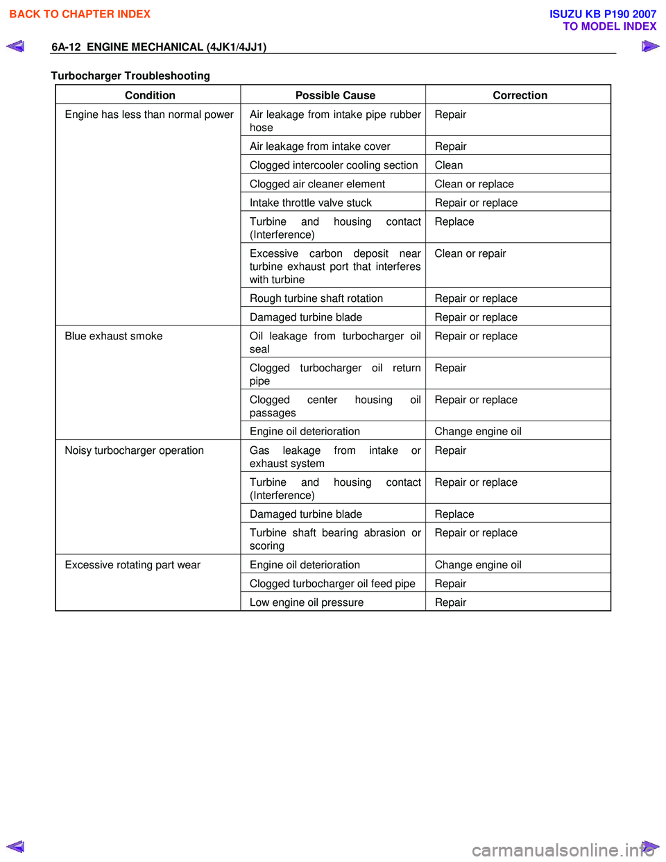
Turbocharger Troubleshooting
Condition Possible Cause Correction
Air leakage from intake pipe rubber
hose Repair
Air leakage from intake cover Repair
Clogged intercooler cooling section Clean
Clogged air cleaner element Clean or replace
Intake throttle valve stuck
Repair or replace
Turbine and housing contact
(Interference) Replace
Excessive carbon deposit near
turbine exhaust port that interferes
with turbine Clean or repair
Rough turbine shaft rotation Repair or replace
Engine has less than normal power
Damaged turbine blade Repair or replace
Oil leakage from turbocharger oil
seal Repair or replace
Clogged turbocharger oil return
pipe Repair
Clogged center housing oil
passages Repair or replace
Blue exhaust smoke
Engine oil deterioration Change engine oil
Gas leakage from intake or
exhaust system Repair
Turbine and housing contact
(Interference) Repair or replace
Damaged turbine blade
Replace
Noisy turbocharger operation
Turbine shaft bearing abrasion or
scoring Repair or replace
Engine oil deterioration
Change engine oil
Clogged turbocharger oil feed pipe Repair
Excessive rotating part wear
Low engine oil pressure Repair
BACK TO CHAPTER INDEX
TO MODEL INDEX
ISUZU KB P190 2007
Page 1589 of 6020

ENGINE ELECTRICAL (4JK1/4JJ1) 6D-1
SECTION 6D
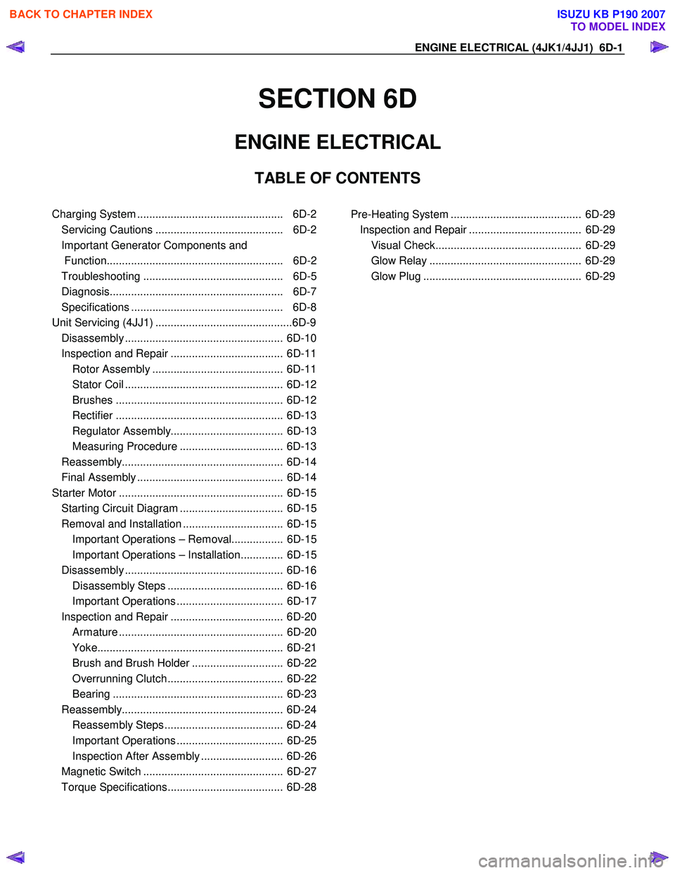
ENGINE ELECTRICAL
TABLE OF CONTENTS
Charging System ................................................ 6D-2
Servicing Cautions .......................................... 6D-2
Important Generator Components and
Function.......................................................... 6D-2
Troubleshooting .............................................. 6D-5
Diagnosis......................................................... 6D-7
Specifications .................................................. 6D-8
Unit Se rv ic ing (4 JJ 1) ....................................... .... ..6D -9
Disassembly .................................................... 6D-10
Inspection and Repair ..................................... 6D-11 Rotor Assembly ........................................... 6D-11
Stator Coil .................................................... 6D-12
Brushes ....................................................... 6D-12
Rectifier ....................................................... 6D-13
Regulator Assembly..................................... 6D-13
Measuring Procedure .................................. 6D-13
Reassembly..................................................... 6D-14
Final Assembly ................................................ 6D-14
Starter Motor ...................................................... 6D-15 Starting Circuit Diagram .................................. 6D-15
Removal and Installation ................................. 6D-15 Important Operations – Removal................. 6D-15
Important Operations – Installation.............. 6D-15
Disassembly .................................................... 6D-16 Disassembly Steps ...................................... 6D-16
Important Operations ................................... 6D-17
Inspection and Repair ..................................... 6D-20 Armature ...................................................... 6D-20
Yoke............................................................. 6D-21
Brush and Brush Holder .............................. 6D-22
Overrunning Clutch...................................... 6D-22
Bearing ........................................................ 6D-23
Reassembly..................................................... 6D-24 Reassembly Steps ....................................... 6D-24
Important Operations ................................... 6D-25
Inspection After Assembly ........................... 6D-26
Magnetic Switch .............................................. 6D-27
Torque Specifications...................................... 6D-28
Pre-Heating System ........................................... 6D-29 Inspection and Repair ..................................... 6D-29 Visual Check................................................ 6D-29
Glow Relay .................................................. 6D-29
Glow Plug .................................................... 6D-29
BACK TO CHAPTER INDEX
TO MODEL INDEX
ISUZU KB P190 2007
Page 1593 of 6020

ENGINE ELECTRICAL (4JK1/4JJ1) 6D-5
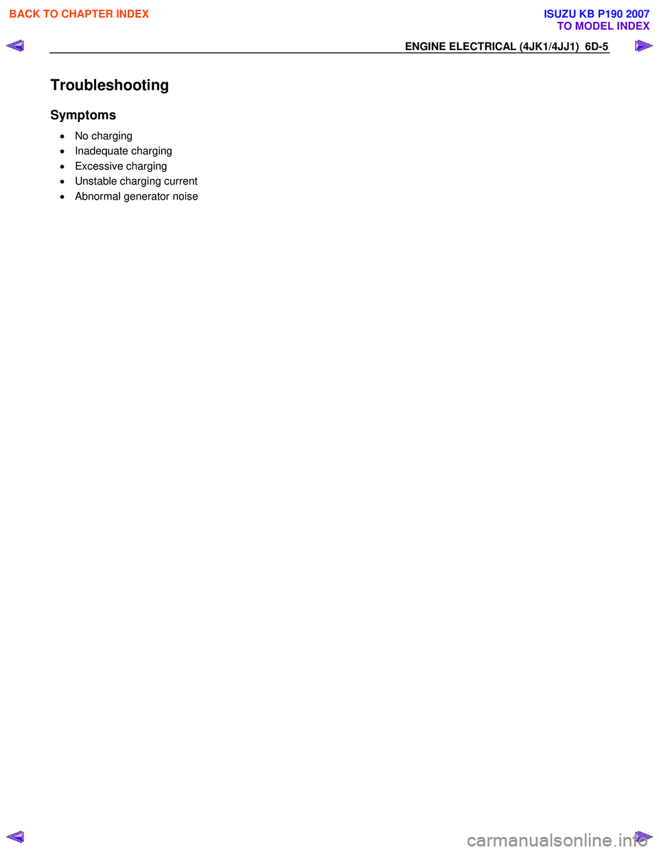
Troubleshooting
Symptoms
• No charging
• Inadequate charging
• Excessive charging
• Unstable charging current
• Abnormal generator noise
BACK TO CHAPTER INDEX
TO MODEL INDEX
ISUZU KB P190 2007
Page 2001 of 6020

ENGINE DIAGNOSIS (C24SE) 6-1
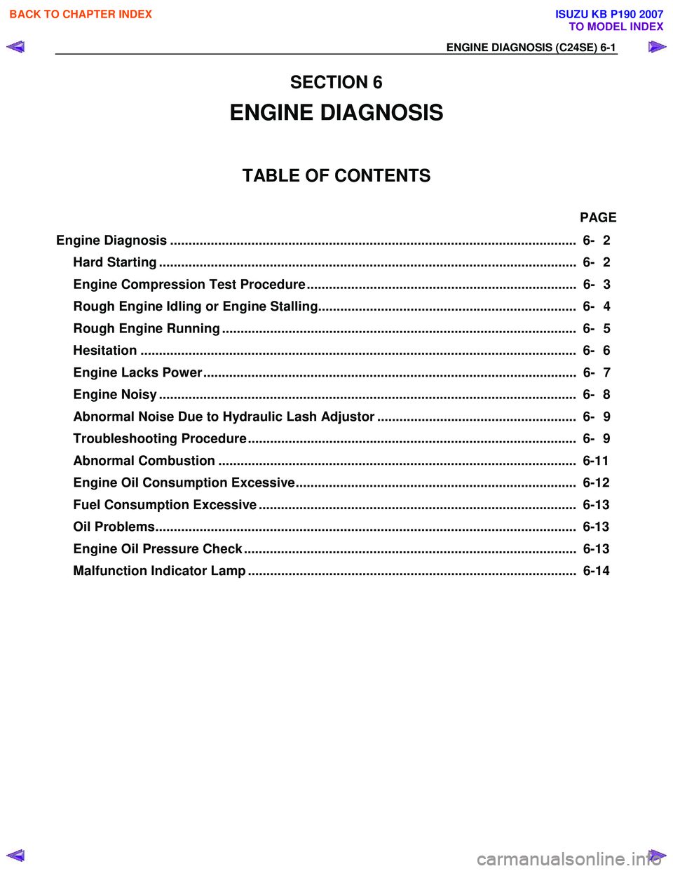
SECTION 6
ENGINE DIAGNOSIS
TABLE OF CONTENTS
PAGE
Engine Diagnosis .............................................................................................................. 6- 2
Hard Starting ................................................................................................................. 6- 2
Engine Compression Test Procedure ......................................................................... 6- 3
Rough Engine Idling or Engine Stalling...................................................................... 6- 4
Rough Engine Running ................................................................................................ 6- 5
Hesitation ..................................................................................................................... . 6- 6
Engine Lacks Power ..................................................................................................... 6- 7
Engine Noisy ................................................................................................................. 6 - 8
Abnormal Noise Due to Hydraulic Lash Adjustor ...................................................... 6- 9
Troubleshooting Procedure ......................................................................................... 6- 9
Abnormal Combustion ................................................................................................. 6-11
Engine Oil Consumption Excessive............................................................................ 6-12
Fuel Consumption Excessive ...................................................................................... 6-13
Oil Problems.................................................................................................................. 6-13
Engine Oil Pressure Check .......................................................................................... 6-13
Malfunction Indicator Lamp ......................................................................................... 6-14
BACK TO CHAPTER INDEX
TO MODEL INDEX
ISUZU KB P190 2007