2007 ISUZU KB P190 fuel type
[x] Cancel search: fuel typePage 1231 of 6020
Engine Control System (4JH1) 6E-197
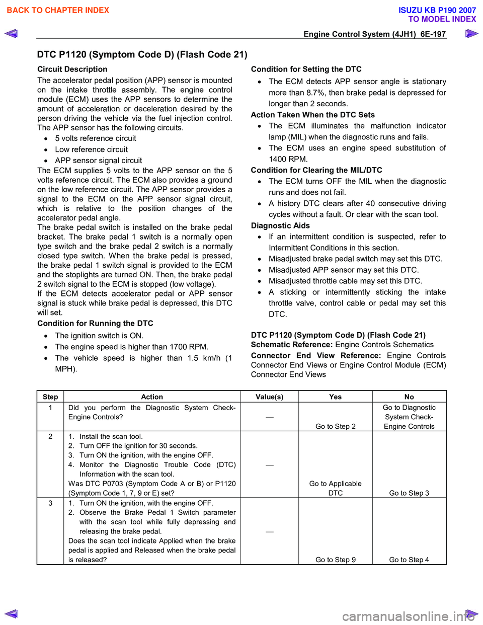
DTC P1120 (Symptom Code D) (Flash Code 21)
Circuit Description
The accelerator pedal position (APP) sensor is mounted
on the intake throttle assembly. The engine control
module (ECM) uses the APP sensors to determine the
amount of acceleration or deceleration desired by the
person driving the vehicle via the fuel injection control.
The APP sensor has the following circuits.
• 5 volts reference circuit
• Low reference circuit
• APP sensor signal circuit
The ECM supplies 5 volts to the APP sensor on the 5
volts reference circuit. The ECM also provides a ground
on the low reference circuit. The APP sensor provides a
signal to the ECM on the APP sensor signal circuit,
which is relative to the position changes of the
accelerator pedal angle.
The brake pedal switch is installed on the brake pedal
bracket. The brake pedal 1 switch is a normally open
type switch and the brake pedal 2 switch is a normally
closed type switch. W hen the brake pedal is pressed,
the brake pedal 1 switch signal is provided to the ECM
and the stoplights are turned ON. Then, the brake pedal
2 switch signal to the ECM is stopped (low voltage).
If the ECM detects accelerator pedal or APP senso
r
signal is stuck while brake pedal is depressed, this DTC
will set.
Condition for Running the DTC
• The ignition switch is ON.
• The engine speed is higher than 1700 RPM.
• The vehicle speed is higher than 1.5 km/h (1
MPH).
Condition for Setting the DTC
• The ECM detects APP sensor angle is stationar
y
more than 8.7%, then brake pedal is depressed fo
r
longer than 2 seconds.
Action Taken When the DTC Sets • The ECM illuminates the malfunction indicato
r
lamp (MIL) when the diagnostic runs and fails.
• The ECM uses an engine speed substitution o
f
1400 RPM.
Condition for Clearing the MIL/DTC • The ECM turns OFF the MIL when the diagnostic
runs and does not fail.
• A history DTC clears after 40 consecutive driving
cycles without a fault. Or clear with the scan tool.
Diagnostic Aids • If an intermittent condition is suspected, refer to
Intermittent Conditions in this section.
• Misadjusted brake pedal switch may set this DTC.
• Misadjusted APP sensor may set this DTC.
• Misadjusted throttle cable may set this DTC.
• A sticking or intermittently sticking the intake
throttle valve, control cable or pedal may set this
DTC.
DTC P1120 (Symptom Code D) (Flash Code 21)
Schematic Reference: Engine Controls Schematics
Connector End View Reference: Engine Controls
Connector End Views or Engine Control Module (ECM)
Connector End Views
Step Action Value(s) Yes No
1 Did you perform the Diagnostic System Check-
Engine Controls?
Go to Step 2 Go to Diagnostic
System Check-
Engine Controls
2 1. Install the scan tool. 2. Turn OFF the ignition for 30 seconds.
3. Turn ON the ignition, with the engine OFF.
4. Monitor the Diagnostic Trouble Code (DTC) Information with the scan tool.
W as DTC P0703 (Symptom Code A or B) or P1120
(Symptom Code 1, 7, 9 or E) set?
Go to Applicable DTC Go to Step 3
3 1. Turn ON the ignition, with the engine OFF. 2. Observe the Brake Pedal 1 Switch parameter with the scan tool while fully depressing and
releasing the brake pedal.
Does the scan tool indicate Applied when the brake
pedal is applied and Released when the brake pedal
is released?
Go to Step 9 Go to Step 4
BACK TO CHAPTER INDEX
TO MODEL INDEX
ISUZU KB P190 2007
Page 1234 of 6020
6E-200 Engine Control System (4JH1)
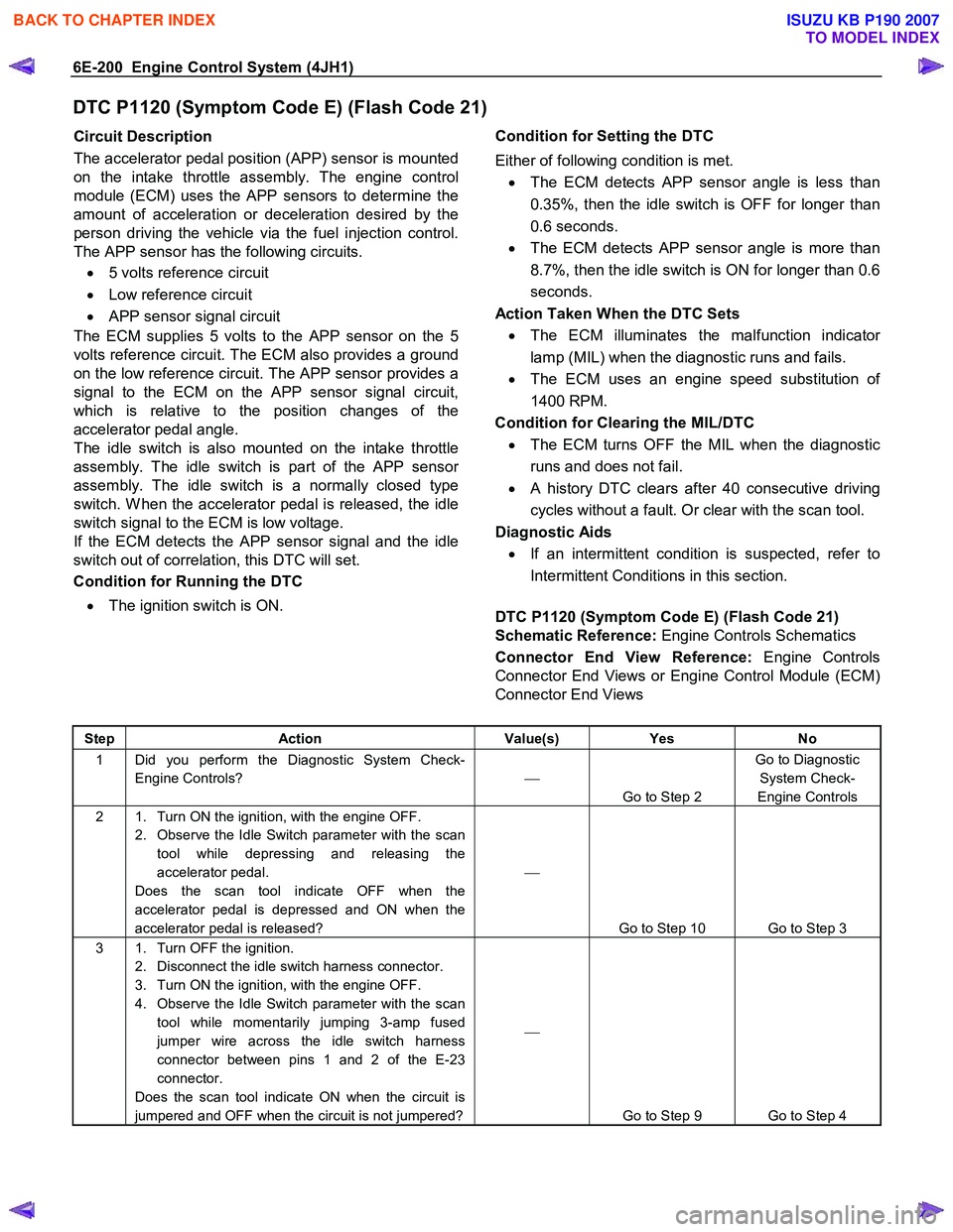
DTC P1120 (Symptom Code E) (Flash Code 21)
Circuit Description
The accelerator pedal position (APP) sensor is mounted
on the intake throttle assembly. The engine control
module (ECM) uses the APP sensors to determine the
amount of acceleration or deceleration desired by the
person driving the vehicle via the fuel injection control.
The APP sensor has the following circuits.
• 5 volts reference circuit
• Low reference circuit
• APP sensor signal circuit
The ECM supplies 5 volts to the APP sensor on the 5
volts reference circuit. The ECM also provides a ground
on the low reference circuit. The APP sensor provides a
signal to the ECM on the APP sensor signal circuit,
which is relative to the position changes of the
accelerator pedal angle.
The idle switch is also mounted on the intake throttle
assembly. The idle switch is part of the APP senso
r
assembly. The idle switch is a normally closed type
switch. W hen the accelerator pedal is released, the idle
switch signal to the ECM is low voltage.
If the ECM detects the
APP sensor signal and the idle
switch out of correlation, this DTC will set.
Condition for Running the DTC
• The ignition switch is ON.
Condition for Setting the DTC
Either of following condition is met. • The ECM detects APP sensor angle is less than
0.35%, then the idle switch is OFF for longer than
0.6 seconds.
• The ECM detects APP sensor angle is more than
8.7%, then the idle switch is ON for longer than 0.6
seconds.
Action Taken When the DTC Sets • The ECM illuminates the malfunction indicato
r
lamp (MIL) when the diagnostic runs and fails.
• The ECM uses an engine speed substitution o
f
1400 RPM.
Condition for Clearing the MIL/DTC • The ECM turns OFF the MIL when the diagnostic
runs and does not fail.
• A history DTC clears after 40 consecutive driving
cycles without a fault. Or clear with the scan tool.
Diagnostic Aids • If an intermittent condition is suspected, refer to
Intermittent Conditions in this section.
DTC P1120 (Symptom Code E) (Flash Code 21)
Schematic Reference: Engine Controls Schematics
Connector End View Reference: Engine Controls
Connector End Views or Engine Control Module (ECM)
Connector End Views
Step Action Value(s) Yes No
1 Did you perform the Diagnostic System Check-
Engine Controls?
Go to Step 2 Go to Diagnostic
System Check-
Engine Controls
2 1. Turn ON the ignition, with the engine OFF. 2. Observe the Idle Switch parameter with the scan tool while depressing and releasing the
accelerator pedal.
Does the scan tool indicate OFF when the
accelerator pedal is depressed and ON when the
accelerator pedal is released?
Go to Step 10 Go to Step 3
3 1. Turn OFF the ignition. 2. Disconnect the idle switch harness connector.
3. Turn ON the ignition, with the engine OFF.
4. Observe the Idle Switch parameter with the scan tool while momentarily jumping 3-amp fused
jumper wire across the idle switch harness
connector between pins 1 and 2 of the E-23
connector.
Does the scan tool indicate ON when the circuit is
jumpered and OFF when the circuit is not jumpered?
Go to Step 9 Go to Step 4
BACK TO CHAPTER INDEX
TO MODEL INDEX
ISUZU KB P190 2007
Page 1241 of 6020
Engine Control System (4JH1) 6E-207
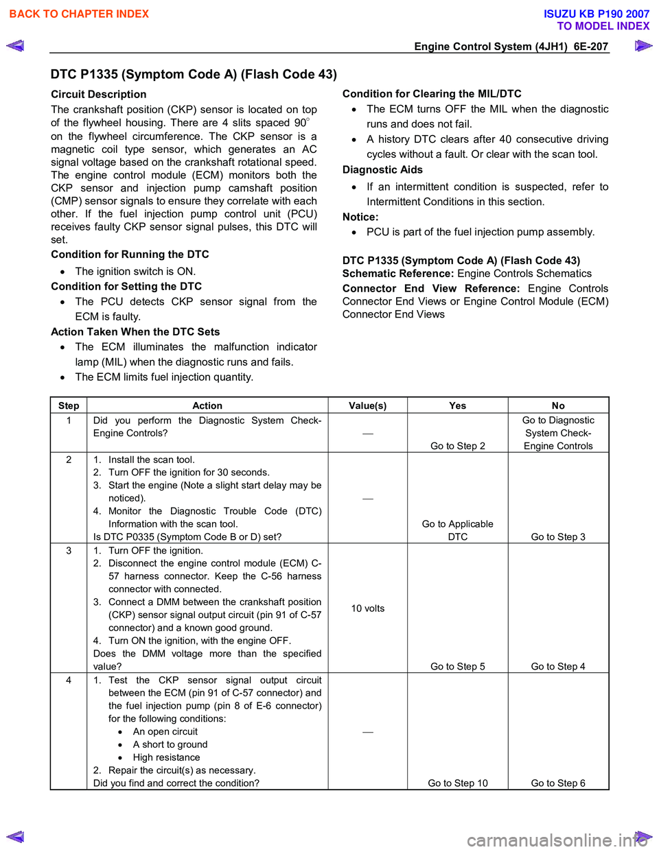
DTC P1335 (Symptom Code A) (Flash Code 43)
Circuit Description
The crankshaft position (CKP) sensor is located on top
of the flywheel housing. There are 4 slits spaced 90 °
on the flywheel circumference. The CKP sensor is a
magnetic coil type sensor, which generates an AC
signal voltage based on the crankshaft rotational speed.
The engine control module (ECM) monitors both the
CKP sensor and injection pump camshaft position
(CMP) sensor signals to ensure they correlate with each
other. If the fuel injection pump control unit (PCU)
receives faulty CKP sensor signal pulses, this DTC will
set.
Condition for Running the DTC
• The ignition switch is ON.
Condition for Setting the DTC • The PCU detects CKP sensor signal from the
ECM is faulty.
Action Taken When the DTC Sets • The ECM illuminates the malfunction indicato
r
lamp (MIL) when the diagnostic runs and fails.
• The ECM limits fuel injection quantity.
Condition for Clearing the MIL/DTC
• The ECM turns OFF the MIL when the diagnostic
runs and does not fail.
• A history DTC clears after 40 consecutive driving
cycles without a fault. Or clear with the scan tool.
Diagnostic Aids
• If an intermittent condition is suspected, refer to
Intermittent Conditions in this section.
Notice: • PCU is part of the fuel injection pump assembly.
DTC P1335 (Symptom Code A) (Flash Code 43)
Schematic Reference: Engine Controls Schematics
Connector End View Reference: Engine Controls
Connector End Views or Engine Control Module (ECM)
Connector End Views
Step Action Value(s) Yes No
1 Did you perform the Diagnostic System Check-
Engine Controls?
Go to Step 2 Go to Diagnostic
System Check-
Engine Controls
2 1. Install the scan tool. 2. Turn OFF the ignition for 30 seconds.
3. Start the engine (Note a slight start delay may be noticed).
4. Monitor the Diagnostic Trouble Code (DTC) Information with the scan tool.
Is DTC P0335 (Symptom Code B or D) set?
Go to Applicable DTC Go to Step 3
3 1. Turn OFF the ignition. 2. Disconnect the engine control module (ECM) C-57 harness connector. Keep the C-56 harness
connector with connected.
3. Connect a DMM between the crankshaft position (CKP) sensor signal output circuit (pin 91 of C-57
connector) and a known good ground.
4. Turn ON the ignition, with the engine OFF.
Does the DMM voltage more than the specified
value? 10 volts
Go to Step 5 Go to Step 4
4 1. Test the CKP sensor signal output circuit between the ECM (pin 91 of C-57 connector) and
the fuel injection pump (pin 8 of E-6 connector)
for the following conditions: • An open circuit
• A short to ground
• High resistance
2. Repair the circuit(s) as necessary.
Did you find and correct the condition?
Go to Step 10 Go to Step 6
BACK TO CHAPTER INDEX
TO MODEL INDEX
ISUZU KB P190 2007
Page 1290 of 6020
6E-256 Engine Control System (4JH1)
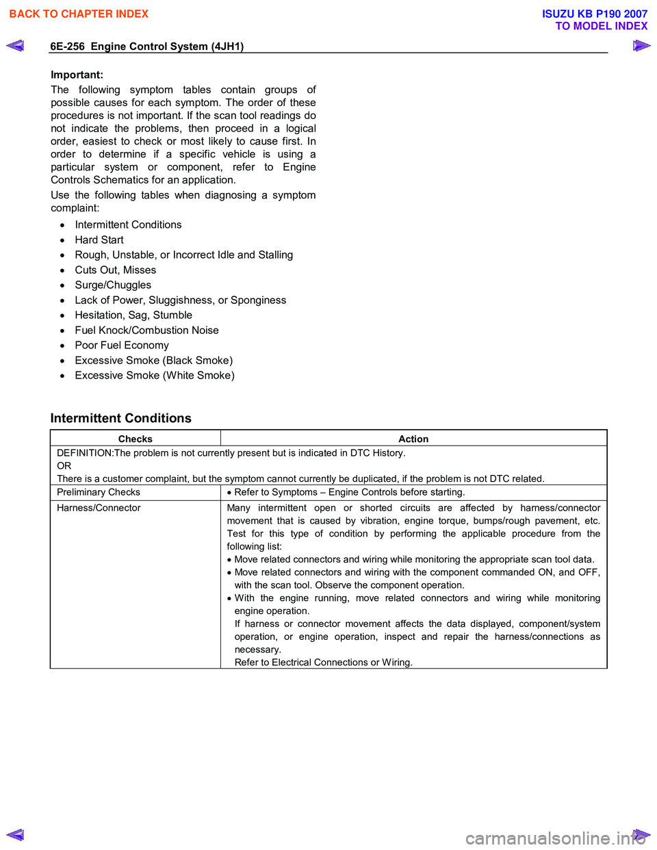
Important:
The following symptom tables contain groups o
f
possible causes for each symptom. The order of these
procedures is not important. If the scan tool readings do
not indicate the problems, then proceed in a logical
order, easiest to check or most likely to cause first. In
order to determine if a specific vehicle is using a
particular system or component, refer to Engine
Controls Schematics for an application.
Use the following tables when diagnosing a symptom
complaint:
• Intermittent Conditions
• Hard Start
• Rough, Unstable, or Incorrect Idle and Stalling
• Cuts Out, Misses
• Surge/Chuggles
• Lack of Power, Sluggishness, or Sponginess
• Hesitation, Sag, Stumble
• Fuel Knock/Combustion Noise
• Poor Fuel Economy
• Excessive Smoke (Black Smoke)
• Excessive Smoke (W hite Smoke)
Intermittent Conditions
Checks Action
DEFINITION:The problem is not currently present but is indicated in DTC History.
OR
There is a customer complaint, but the symptom cannot currently be duplicated, if the problem is not DTC related.
Preliminary Checks • Refer to Symptoms – Engine Controls before starting.
Harness/Connector Many intermittent open or shorted circuits are affected by harness/connector
movement that is caused by vibration, engine torque, bumps/rough pavement, etc.
Test for this type of condition by performing the applicable procedure from the
following list:
• Move related connectors and wiring while monitoring the appropriate scan tool data.
• Move related connectors and wiring with the component commanded ON, and OFF,
with the scan tool. Observe the component operation.
• W ith the engine running, move related connectors and wiring while monitoring
engine operation.
If harness or connector movement affects the data displayed, component/system
operation, or engine operation, inspect and repair the harness/connections as
necessary.
Refer to Electrical Connections or W iring.
BACK TO CHAPTER INDEX
TO MODEL INDEX
ISUZU KB P190 2007
Page 1292 of 6020
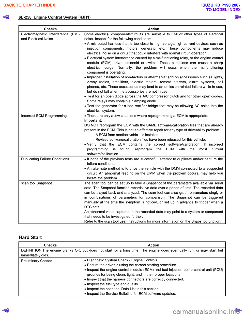
6E-258 Engine Control System (4JH1)
Checks Action
Electromagnetic Interference (EMI)
and Electrical Noise Some electrical components/circuits are sensitive to EMI or other types of electrical
noise. Inspect for the following conditions:
• A misrouted harness that is too close to high voltage/high current devices such as
injection components, motors, generator etc. These components may induce
electrical noise on a circuit that could interfere with normal circuit operation.
• Electrical system interference caused by a malfunctioning relay, or the engine control
module (ECM) driven solenoid or switch. These conditions can cause a sharp
electrical surge. Normally, the problem will occur when the malfunctioning
component is operating.
• Improper installation of non-factory or aftermarket add on accessories such as lights,
2-way radios, amplifiers, electric motors, remote starters, alarm systems, cell
phones, etc. These accessories may lead to an emission related failure while in use,
but do not fail when the accessories are not in use.
• Test for an open diode across the A/C compressor clutch and for other open diodes.
Some relays may contain a clamping diode.
• Test the generator for a bad rectifier bridge that may be allowing AC noise into the
electrical system.
Incorrect ECM Programming • There are only a few situations where reprogramming a ECM is appropriate:
Important:
DO NOT reprogram the ECM with the SAME software/calibration files that are already
present in the ECM. This is not an effective repair for any type of driveability problem. - A ECM from another vehicle is installed.
- Revised software/calibration files have been released for this vehicle.
• Verify that the ECM contains the correct software/calibration. If incorrect
programming is found, reprogram the ECM with the most current
software/calibration.
Duplicating Failure Conditions • If none of the previous tests are successful, attempt to duplicate and/or capture the
failure conditions.
• An alternate method is to drive the vehicle with the DMM connected to a suspected
circuit. An abnormal reading on the DMM when the problem occurs, may help you
locate the problem.
scan tool Snapshot The scan tool can be set up to take a Snapshot of the parameters available via serial
data. The Snapshot function records live data over a period of time. The recorded data
can be played back and analyzed. The scan tool can also graph parameters singly or
in combinations of parameters for comparison. The Snapshot can be triggered
manually at the time the symptom is noticed, or set up in advance to trigger when a
DTC sets.
An abnormal value captured in the recorded data may point to a system or component
that needs to be investigated further.
Refer to the scan tool user instructions for more information on the Snapshot function.
Hard Start
Checks Action
DEFINITION:The engine cranks OK, but does not start for a long time. The engine does eventually run, or may start but
immediately dies.
Preliminary Checks •
Diagnostic System Check - Engine Controls.
• Ensure the driver is using the correct starting procedure.
• Inspect the engine control module (ECM) and fuel injection pump control unit (PCU)
grounds for being clean, tight, and in their proper locations.
• Inspect that the harness connectors are correctly connected.
• Inspect the fuel type and quality.
• Inspect the scan tool Data List in this section.
• Inspect the Service Bulletins for ECM software updates.
BACK TO CHAPTER INDEX
TO MODEL INDEX
ISUZU KB P190 2007
Page 1293 of 6020
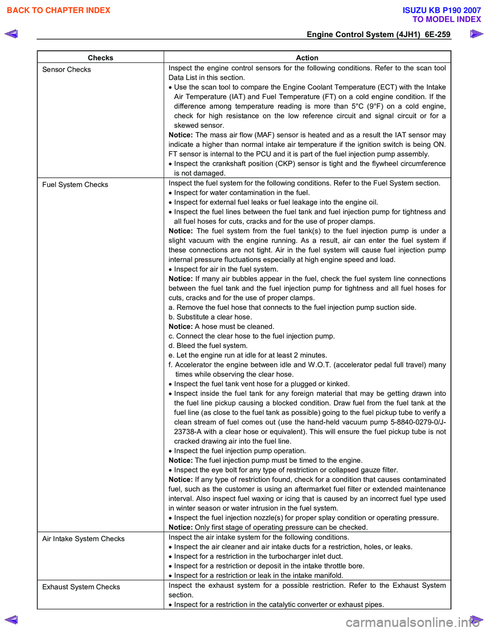
Engine Control System (4JH1) 6E-259
Checks Action
Sensor Checks Inspect the engine control sensors for the following conditions. Refer to the scan tool
Data List in this section.
• Use the scan tool to compare the Engine Coolant Temperature (ECT) with the Intake
Air Temperature (IAT) and Fuel Temperature (FT) on a cold engine condition. If the
difference among temperature reading is more than 5°C (9°F) on a cold engine,
check for high resistance on the low reference circuit and signal circuit or for a
skewed sensor.
Notice: The mass air flow (MAF) sensor is heated and as a result the IAT sensor may
indicate a higher than normal intake air temperature if the ignition switch is being ON.
FT sensor is internal to the PCU and it is part of the fuel injection pump assembly.
• Inspect the crankshaft position (CKP) sensor is tight and the flywheel circumference
is not damaged.
Fuel System Checks Inspect the fuel system for the following conditions. Refer to the Fuel System section.
• Inspect for water contamination in the fuel.
• Inspect for external fuel leaks or fuel leakage into the engine oil.
• Inspect the fuel lines between the fuel tank and fuel injection pump for tightness and
all fuel hoses for cuts, cracks and for the use of proper clamps.
Notice: The fuel system from the fuel tank(s) to the fuel injection pump is under a
slight vacuum with the engine running. As a result, air can enter the fuel system if
these connections are not tight. Air in the fuel system will cause fuel injection pump
internal pressure fluctuations especially at high engine speed and load.
• Inspect for air in the fuel system.
Notice: If many air bubbles appear in the fuel, check the fuel system line connections
between the fuel tank and the fuel injection pump for tightness and all fuel hoses for
cuts, cracks and for the use of proper clamps.
a. Remove the fuel hose that connects to the fuel injection pump suction side.
b. Substitute a clear hose.
Notice: A hose must be cleaned.
c. Connect the clear hose to the fuel injection pump.
d. Bleed the fuel system.
e. Let the engine run at idle for at least 2 minutes.
f. Accelerator the engine between idle and W .O.T. (accelerator pedal full travel) many times while observing the clear hose.
• Inspect the fuel tank vent hose for a plugged or kinked.
• Inspect inside the fuel tank for any foreign material that may be getting drawn into
the fuel line pickup causing a blocked condition. Draw fuel from the fuel tank at the
fuel line (as close to the fuel tank as possible) going to the fuel pickup tube to verify a
clean stream of fuel comes out (use the hand-held vacuum pump 5-8840-0279-0/J-
23738-A with a clear hose or equivalent). This will ensure the fuel pickup tube is not
cracked drawing air into the fuel line.
• Inspect the fuel injection pump operation.
Notice: The fuel injection pump must be timed to the engine.
• Inspect the eye bolt for any type of restriction or collapsed gauze filter.
Notice: If any type of restriction found, check for a condition that causes contaminated
fuel, such as the customer is using an aftermarket fuel filter or extended maintenance
interval. Also inspect fuel waxing or icing that is caused by an incorrect fuel type used
in winter season or water intrusion in the fuel system.
• Inspect the fuel injection nozzle(s) for proper splay condition or operating pressure.
Notice: Only first stage of operating pressure can be checked.
Air Intake System Checks Inspect the air intake system for the following conditions.
• Inspect the air cleaner and air intake ducts for a restriction, holes, or leaks.
• Inspect for a restriction in the turbocharger inlet duct.
• Inspect for a restriction or deposit in the intake throttle bore.
• Inspect for a restriction or leak in the intake manifold.
Exhaust System Checks Inspect the exhaust system for a possible restriction. Refer to the Exhaust System
section.
• Inspect for a restriction in the catalytic converter or exhaust pipes.
BACK TO CHAPTER INDEX
TO MODEL INDEX
ISUZU KB P190 2007
Page 1294 of 6020
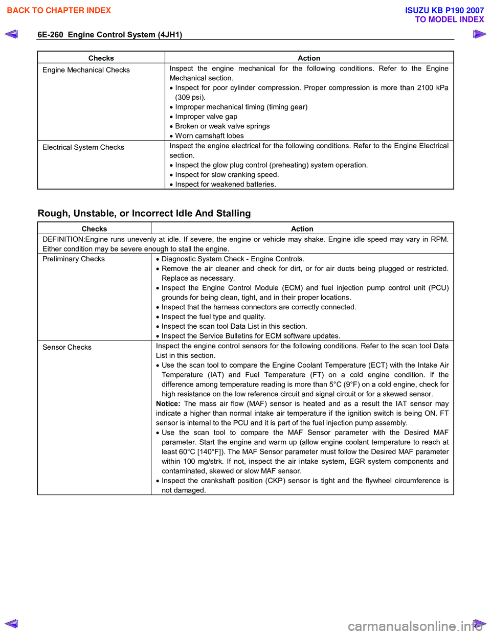
6E-260 Engine Control System (4JH1)
Checks Action
Engine Mechanical Checks Inspect the engine mechanical for the following conditions. Refer to the Engine
Mechanical section.
• Inspect for poor cylinder compression. Proper compression is more than 2100 kPa
(309 psi).
• Improper mechanical timing (timing gear)
• Improper valve gap
• Broken or weak valve springs
• W orn camshaft lobes
Electrical System Checks Inspect the engine electrical for the following conditions. Refer to the Engine Electrical
section.
• Inspect the glow plug control (preheating) system operation.
• Inspect for slow cranking speed.
• Inspect for weakened batteries.
Rough, Unstable, or Incorrect Idle And Stalling
Checks Action
DEFINITION:Engine runs unevenly at idle. If severe, the engine or vehicle may shake. Engine idle speed may vary in RPM.
Either condition may be severe enough to stall the engine.
Preliminary Checks • Diagnostic System Check - Engine Controls.
• Remove the air cleaner and check for dirt, or for air ducts being plugged or restricted.
Replace as necessary.
• Inspect the Engine Control Module (ECM) and fuel injection pump control unit (PCU)
grounds for being clean, tight, and in their proper locations.
• Inspect that the harness connectors are correctly connected.
• Inspect the fuel type and quality.
• Inspect the scan tool Data List in this section.
• Inspect the Service Bulletins for ECM software updates.
Sensor Checks Inspect the engine control sensors for the following conditions. Refer to the scan tool Data
List in this section.
• Use the scan tool to compare the Engine Coolant Temperature (ECT) with the Intake Air
Temperature (IAT) and Fuel Temperature (FT) on a cold engine condition. If the
difference among temperature reading is more than 5°C (9°F) on a cold engine, check for
high resistance on the low reference circuit and signal circuit or for a skewed sensor.
Notice: The mass air flow (MAF) sensor is heated and as a result the IAT sensor may
indicate a higher than normal intake air temperature if the ignition switch is being ON. FT
sensor is internal to the PCU and it is part of the fuel injection pump assembly.
• Use the scan tool to compare the MAF Sensor parameter with the Desired MAF
parameter. Start the engine and warm up (allow engine coolant temperature to reach at
least 60°C [140°F]). The MAF Sensor parameter must follow the Desired MAF parameter
within 100 mg/strk. If not, inspect the air intake system, EGR system components and
contaminated, skewed or slow MAF sensor.
• Inspect the crankshaft position (CKP) sensor is tight and the flywheel circumference is
not damaged.
BACK TO CHAPTER INDEX
TO MODEL INDEX
ISUZU KB P190 2007
Page 1295 of 6020
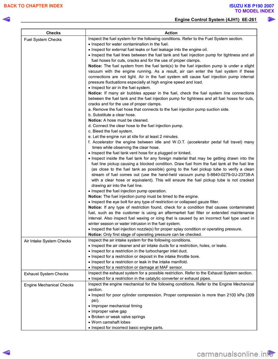
Engine Control System (4JH1) 6E-261
Checks Action
Fuel System Checks Inspect the fuel system for the following conditions. Refer to the Fuel System section.
• Inspect for water contamination in the fuel.
• Inspect for external fuel leaks or fuel leakage into the engine oil.
• Inspect the fuel lines between the fuel tank and fuel injection pump for tightness and all
fuel hoses for cuts, cracks and for the use of proper clamps.
Notice: The fuel system from the fuel tank(s) to the fuel injection pump is under a slight
vacuum with the engine running. As a result, air can enter the fuel system if these
connections are not tight. Air in the fuel system will cause fuel injection pump internal
pressure fluctuations especially at high engine speed and load.
• Inspect for air in the fuel system.
Notice: If many air bubbles appear in the fuel, check the fuel system line connections
between the fuel tank and the fuel injection pump for tightness and all fuel hoses for cuts,
cracks and for the use of proper clamps.
a. Remove the fuel hose that connects to the fuel injection pump suction side.
b. Substitute a clear hose.
Notice: A hose must be cleaned.
d. Connect the clear hose to the fuel injection pump.
c. Bleed the fuel system.
e. Let the engine run at idle for at least 2 minutes.
f. Accelerator the engine between idle and W .O.T. (accelerator pedal full travel) many times while observing the clear hose.
• Inspect the fuel tank vent hose for a plugged or kinked.
• Inspect inside the fuel tank for any foreign material that may be getting drawn into the
fuel line pickup causing a blocked condition. Draw fuel from the fuel tank at the fuel line
(as close to the fuel tank as possible) going to the fuel pickup tube to verify a clean
stream of fuel comes out (use the hand-held vacuum pump 5-8840-0279-0/J-23738-A
with a clear hose or equivalent). This will ensure the fuel pickup tube is not cracked
drawing air into the fuel line.
• Inspect the fuel injection pump operation.
Notice: The fuel injection pump must be timed to the engine.
• Inspect the eye bolt for any type of restriction or collapsed gauze filter.
Notice: If any type of restriction found, check for a condition that causes contaminated
fuel, such as the customer is using an aftermarket fuel filter or extended maintenance
interval. Also inspect fuel waxing or icing that is caused by an incorrect fuel type used in
winter season or water intrusion in the fuel system.
• Inspect the fuel injection nozzle(s) for proper splay condition or operating pressure.
Notice: Only first stage of operating pressure can be checked.
Air Intake System Checks Inspect the air intake system for the following conditions.
• Inspect the air cleaner and air intake ducts for a restriction, holes, or leaks.
• Inspect for a restriction in the turbocharger inlet duct.
• Inspect for a restriction or deposit in the intake throttle bore.
• Inspect for a restriction or leak in the intake manifold.
• Inspect for a restriction or damage at MAF sensor.
Exhaust System Checks Inspect the exhaust system for a possible restriction. Refer to the Exhaust System section.
• Inspect for a restriction in the catalytic converter or exhaust pipes.
Engine Mechanical Checks Inspect the engine mechanical for the following conditions. Refer to the Engine Mechanical
section.
• Inspect for poor cylinder compression. Proper compression is more than 2100 kPa (309
psi).
• Improper mechanical timing
• Improper valve gap
• Broken or weak valve springs
• W orn camshaft lobes
• Inspect for incorrect basic engine parts.
BACK TO CHAPTER INDEX
TO MODEL INDEX
ISUZU KB P190 2007